EP0744847A1 - Redundantes Datenübertragungssystem mit mindestens zwei Kanälen - Google Patents
Redundantes Datenübertragungssystem mit mindestens zwei Kanälen Download PDFInfo
- Publication number
- EP0744847A1 EP0744847A1 EP96201328A EP96201328A EP0744847A1 EP 0744847 A1 EP0744847 A1 EP 0744847A1 EP 96201328 A EP96201328 A EP 96201328A EP 96201328 A EP96201328 A EP 96201328A EP 0744847 A1 EP0744847 A1 EP 0744847A1
- Authority
- EP
- European Patent Office
- Prior art keywords
- delay
- circuit
- information
- channels
- transmitted
- Prior art date
- Legal status (The legal status is an assumption and is not a legal conclusion. Google has not performed a legal analysis and makes no representation as to the accuracy of the status listed.)
- Granted
Links
Images


Classifications
-
- H—ELECTRICITY
- H04—ELECTRIC COMMUNICATION TECHNIQUE
- H04W—WIRELESS COMMUNICATION NETWORKS
- H04W40/00—Communication routing or communication path finding
- H04W40/02—Communication route or path selection, e.g. power-based or shortest path routing
- H04W40/12—Communication route or path selection, e.g. power-based or shortest path routing based on transmission quality or channel quality
-
- H—ELECTRICITY
- H04—ELECTRIC COMMUNICATION TECHNIQUE
- H04L—TRANSMISSION OF DIGITAL INFORMATION, e.g. TELEGRAPHIC COMMUNICATION
- H04L1/00—Arrangements for detecting or preventing errors in the information received
- H04L1/004—Arrangements for detecting or preventing errors in the information received by using forward error control
- H04L1/0056—Systems characterized by the type of code used
- H04L1/0061—Error detection codes
-
- H—ELECTRICITY
- H04—ELECTRIC COMMUNICATION TECHNIQUE
- H04B—TRANSMISSION
- H04B1/00—Details of transmission systems, not covered by a single one of groups H04B3/00 - H04B13/00; Details of transmission systems not characterised by the medium used for transmission
- H04B1/74—Details of transmission systems, not covered by a single one of groups H04B3/00 - H04B13/00; Details of transmission systems not characterised by the medium used for transmission for increasing reliability, e.g. using redundant or spare channels or apparatus
-
- H—ELECTRICITY
- H04—ELECTRIC COMMUNICATION TECHNIQUE
- H04B—TRANSMISSION
- H04B7/00—Radio transmission systems, i.e. using radiation field
- H04B7/14—Relay systems
-
- H—ELECTRICITY
- H04—ELECTRIC COMMUNICATION TECHNIQUE
- H04L—TRANSMISSION OF DIGITAL INFORMATION, e.g. TELEGRAPHIC COMMUNICATION
- H04L1/00—Arrangements for detecting or preventing errors in the information received
- H04L1/22—Arrangements for detecting or preventing errors in the information received using redundant apparatus to increase reliability
-
- H—ELECTRICITY
- H04—ELECTRIC COMMUNICATION TECHNIQUE
- H04L—TRANSMISSION OF DIGITAL INFORMATION, e.g. TELEGRAPHIC COMMUNICATION
- H04L1/00—Arrangements for detecting or preventing errors in the information received
- H04L2001/0092—Error control systems characterised by the topology of the transmission link
- H04L2001/0096—Channel splitting in point-to-point links
Definitions
- United States Patent No. USP 3,409,875 describes such a system.
- the delay element providing a delay T is permanently associated with one of the output ports of the transmission device, while the output port of the reception device is connected to one of the canals.
- a quality measurement circuit analyzes by comparison the signals from the two channels and as soon as a discrepancy is reported, the output access of the receiving device is connected to the other channel which acts as a backup channel for a period of time. fixed T.
- good efficiency is obtained against disturbances, grouped in a time interval less than T, which simultaneously affect the channels.
- this system is not suitable when the channels cause variable and unpredictable delay to the signals they carry, since it is no longer possible to analyze the quality of information by coincidence.
- this system does not eliminate the errors which occur on the emergency channel, when the latter is connected to the outlet access.
- the present invention provides a system of the kind mentioned in the preamble which does not have said drawback.
- such a system is remarkable in that it is provided, at the level of the transmission device, a cutting circuit for cutting the information to be transmitted into blocks and an assignment circuit for assigning a detector code. errors to each of these blocks and, at the receiving device, an error code analysis circuit which provides an indication of false block.
- the system of the invention is formed by a transmission device 1 comprising an access 5 for the transmission to be transmitted, two accesses 7A and 7B for supplying the same transmission information on channels CHA and CHB .
- a delay element 8 inserted in the path of the CHB channel delays the information on this channel by a duration T.
- the system is also formed of a reception device 10 comprising ports 11A and 11B for receiving the information transmitted from the channels CHA and CHB.
- a reception delay element 12 to restore the delay caused by the transmission element 8
- a quality measurement circuit 15 whose inputs receive the information transmitted and which determine, as a function of this measurement, which of the channels will be connected to the output port 20.
- the circuit 15 acts on a switch 22.
- the transmission system of FIG. 1 comprises, arranged in the transmission device, a code insertion circuit for error detection bearing the reference 30 while the quality measurement circuit 15 is formed of two error code analyzer circuits 32 and 33, the inputs of which receive the information from channels 11A and 11B. a function of the errors detected, a control circuit 35 determines, by acting on the switch circuit 22, which of the channels must be connected to the output 20.
- the circuit 30 is formed of a chopping circuit 40 to form blocks from the information received at access 5 and from a calculation circuit 42 to form a cyclic redundancy code relating to each of the blocks, produced by the cutting circuit 40. On an output 43 a signal appears to indicate the start of 'a block.
- FIG. 2 shows how the detection code is inserted into the information to be transmitted from the access 5.
- the information to be transmitted is shown schematically, which is presented here, by way of example, continuously.
- the information is divided into blocks: BL (i), BL (i + 1), BL (i + 2), BL (i + 3) ...
- a each of these blocks is respectively assigned a cyclic redundancy code CRC (i-1), CRC (i), CRC (i + 1), CRC (i + 2) ...
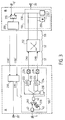
- FIG. 3 shows a second system according to the invention.
- This system is formed around a bidirectional link which allows the exchange of information between a site A and a site B.
- the information to be transmitted from site A is applied to access 5 and that to be sent from site B to a 5 'access.
- the information received at these sites is found at access 20 for site B and at access 20 'for site A.
- These sites are linked by channels CHA and CHB for the direction from site A to site B and by CHA 'and CHB' channels for the opposite direction.
- it is assumed that all the transmission and reception devices have identical structures.
- Channels CHA and CHB connect a transmission device 100 forming part of site A with a receiving device 110 forming part of site B.
- Channels CHA 'and CHB' connect a second transmission device 200 of site B with a second reception device 210 of site A.
- the CHA and CHB channels can borrow, according to certain configurations, a network 112 which can introduce compensation for the effect sought by the implementation of the system of FIG. 1.
- a transmission section S1 on copper such as an HDSL section
- a transmission section S2 comprising the network 112 of the SDH type (such as a VC12) and a second S3 transmission section on copper (HDSL).
- the synchronous network 112 compensates for the delay introduced by the transmission device 100 on the CHB channel, as shown in FIG. 1, by delaying the CHA channel with respect to the CHB channel, the two channels may end up in phase ( or approximately) at the start of the second section S3.
- the probability that this case occurs is all the higher as the optimal delay T, and the path difference introduced by the synchronous network, are typically of the same order of magnitude, namely a few milliseconds.
- the masking of the errors caused by a pulse-shaped noise on the second section S3 (HDSL) is then ineffective.
- delay members 212 and 214 arranged in FIG. 3 in the transmission device 100 and provided respectively with control commands.
- inhibition 222 and 224 represented in the form of switches short-circuiting or not these delay members.
- These delay members 212, 214 are connected respectively to the channels CHA and CHB by means of modulation circuits 226 and 228 which allow propagation by these channels.
- An inhibition control circuit 230 controls these short circuits. To effect these short circuits, the circuit 230 is controlled by inhibition information CT developed at the level of the reception device 110 and which is transmitted by the return channel which is constituted by the channels CHA 'and CHB'.
- This inhibition information is formed by a delay determination device 235, notably from the phase shift of the information transmitted by the channels CHA and CHB.
- the value of this phase shift is measured by a phase shift measurement circuit 250, the two inputs of which receive said information transmitted by the channels CHA and CHB.
- the delay determination device 235 supplies, at its output 236, the inhibition information to a multiplexer 255 which multiplexes this information with that to be transmitted from the access 5 ′ so that it is transmitted, via the transmission device 200 to the inhibition control circuit 230 of site A via the channels CHA 'and CHB'.
- the blocks indicated relate to the exchange of information between the device 200 and the device 210 in the case of a symmetrical bidirectional transmission.
- CT information can be structured differently in the case of asymmetric transmission.
- the phase shift measurement circuit 250 determines this phase shift by measuring the time between the appearance of the same block number on the two channels CHA and CHB.
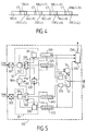
- FIG. 5 shows in detail the reception device 110.
- the circuit 32 is formed by an error code calculation circuit 310 and a code comparison circuit 311 which performs the comparison of the codes calculated by the circuit 310 and of the transmitted code, calculated by the circuit 42 and restored at the output of a demultiplexer 320.
- This demultiplexer 320 also provides the useful information, the blocks BL (i), to a variable delay member 325 and the block numbers NBL (i) to the circuit 250.
- the comparison information at the output of the circuit 311, which determines the erroneous state of the blocks, is applied to a second delay member variable 333 comprising the same number of cells as the member 325.
- the information at the output of the member 325 is systematically delayed by a delay member 335 before being applied to the switch 22.
- the same elements relating to the channel are found again CHB.
- the elements: 350, 351, 360, 365, 373 and 375 are to be compared with the elements 310, 311, 320, 325, 333 and 335.
- a circuit 390 supplies signals H'bl to indicate the start of a block on its output 391 as a function of signals recovered from the demultiplexers 320 and 360. These signals correspond to the blocks put back in phase at the output of the organs 325 and 365 This resetting in phase is obtained by the circuit 250 which determines the delay to be brought by the organs 325 and 365, as well as the delay to be brought by the organs 333 and 373, so that the information is indeed in phase at the inputs of the organs. late 335 and 375.
- the delay members 335 and 375 allow the control circuit 35 time to dispose of the states of the blocks before they leave said delay members.
- the delay determination circuit 235 determines the delay member 212 or the member 214 to short-circuit according to the phase shift measurements, as has already been said. This constitutes the information CT which is transmitted to the transmission device 100.
- the delay determination device 235 transmits the inhibition command from the member 214 and therefore d activation of the organ 212. Otherwise, the delay determination device 235 maintains the command to inhibit the organ 214 and therefore to activate the organ 212.
- the choice to apply the delay T results from a compromise between on the one hand, the error packets which one wishes to mask and on the other hand, the service specifications of the two-way links, which on the contrary impose delays as short as possible.
- the presence of impulse noise is only observed on certain lines of the distribution network. In order to introduce a delay only in cases where this is necessary, it would be possible, during the commissioning and qualification phase of the link, to carry out impulse noise measurements. However, the operational costs of such measures can be prohibitive.
- the noise in the form of a pulse comes from an electromagnetic activity which may not manifest itself. only at certain times of the day. When user applications can overcome occasional changes in the transmission delay, it may be desirable to apply the delay only during periods when impulse noise is present.
- the integration time Ti is a configuration parameter of the receiver.
- the integrators are used by the following method, to decide whether to activate or inhibit the delay T: As long as the effects of the impulse noise remain below a threshold Ri, the delay determining device 235 forces the delay T to 0. This condition is satisfied as long as Pe (t) ⁇ Ri. Ri is a configuration parameter of the reception device 110.
- the delay determining device 235 fixes the delay at the value T until Pe again becomes less than Ri.
- the method described above makes it possible to activate the delay T optimally, when the reception device 110 of site B is configured at the values (Ti, Ri) which characterize the transmission performance perceived by the user of the link.
- An identical process is suitable for the couple formed by the devices 200 and 210.
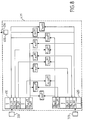
- FIG. 7 shows another embodiment of a system according to the invention in which means are provided to allow the choice of the value of the delay to be applied to the transmission to be automated.
- the delay members 212 are formed of a cascade of delay members 212 1 ... 212 M in the CHA channel and the member 214 of a cascade of delay members 214 1 ... 214 M in the CHB channel.
- Each of these organs provides a delay ⁇ equal to the duration of a block.
- the delay provided by these members 212 and 214 can vary from 0 to M ⁇ by increment of ⁇ .
- M ⁇ corresponds to the maximum delay that can be allocated to the error cancellation function.
- the principle consists in anticipating what would be the performance improvement obtained if the delay were reduced by the duration of 1, then 2, then 3, ... blocks. If these anticipations do not give satisfactory results, then the anticipation mechanism searches for the effect of increasing the duration delay by 1, then 2, then 3 ... blocks.
- the precision of the mechanism is all the greater when the size of the blocks of the frame considered is small compared to the lengths of the error packets.
- This mechanism can be implemented as follows, using the delay determination device 435 shown in FIG. 8 and which is to be compared to the device 235 shown in FIG. 6. The method is implemented by a circuit 455 which takes into account in particular the information provided by the integrators which will be discussed below.
- the set of integrators is used by the following method, to determine the optimal value of the delay T equal to m ⁇ at time t and assumed to be applied to the transmission of the CHB channel: As long as the effects of the impulse noise remain below the threshold Ri, the device 435 forces the delay T to 0.
- P E / (t) 1 2 P E (t) + VS Mm, M (t) VS Mm, M (t) + C Mm, M / (t) If the threshold Ri is crossed then: find the largest integer k, between 1 and m, such as Rd.C Mk, M (t) ⁇ C M, M (t). If k exists, then the device 435 issues the command to reduce T by the duration of k ⁇ . Otherwise, then look for the smallest integer k, between 1 and Mm, such that Rc.C M, Mk (t) ⁇ C M, M (t).
- Rd and Rc are configuration parameters of the receiver. If k exists, then the device 435 issues the command to increase T by the duration of k ⁇ . If not, then resume threshold detection Rd. Otherwise, then resume threshold detection Ri.
- the method described above makes it possible to adjust the delay T optimally, by configuring the couple transmitting device 100 and the receiving device 110 at the values (Ti, Ri, Rd, Rc) which characterize the transmission performance perceived by the link user. Such a method is obviously suitable for the pairing device 200 and receiving device 210.
Landscapes
- Engineering & Computer Science (AREA)
- Computer Networks & Wireless Communication (AREA)
- Signal Processing (AREA)
- Detection And Prevention Of Errors In Transmission (AREA)
- Data Exchanges In Wide-Area Networks (AREA)
Applications Claiming Priority (2)
| Application Number | Priority Date | Filing Date | Title |
|---|---|---|---|
| FR9506137 | 1995-05-23 | ||
| FR9506137 | 1995-05-23 |
Publications (2)
| Publication Number | Publication Date |
|---|---|
| EP0744847A1 true EP0744847A1 (de) | 1996-11-27 |
| EP0744847B1 EP0744847B1 (de) | 2005-08-24 |
Family
ID=9479298
Family Applications (1)
| Application Number | Title | Priority Date | Filing Date |
|---|---|---|---|
| EP96201328A Expired - Lifetime EP0744847B1 (de) | 1995-05-23 | 1996-05-14 | Redundantes Datenübertragungssystem mit mindestens zwei Kanälen |
Country Status (7)
| Country | Link |
|---|---|
| US (1) | US5835483A (de) |
| EP (1) | EP0744847B1 (de) |
| JP (1) | JP3798845B2 (de) |
| KR (1) | KR100419944B1 (de) |
| CN (1) | CN1108019C (de) |
| DE (1) | DE69635095T2 (de) |
| MY (1) | MY132226A (de) |
Cited By (2)
| Publication number | Priority date | Publication date | Assignee | Title |
|---|---|---|---|---|
| WO1998038829A3 (en) * | 1997-02-27 | 1998-12-17 | Excel Switching Corp | Redundancy, expanded switching capacity and fault isolation arrangements for expandable telecommunications system |
| WO1999020007A1 (en) * | 1997-10-09 | 1999-04-22 | Usa Digital Radio, Inc. | A system and method for mitigating intermittent interruptions in an audio radio broadcast system |
Families Citing this family (21)
| Publication number | Priority date | Publication date | Assignee | Title |
|---|---|---|---|---|
| JP3319331B2 (ja) * | 1997-04-04 | 2002-08-26 | 日本電気株式会社 | 双方向通信システムにおける遅延量/送信レベル設定方式 |
| JP3974712B2 (ja) * | 1998-08-31 | 2007-09-12 | 富士通株式会社 | ディジタル放送用送信・受信再生方法及びディジタル放送用送信・受信再生システム並びにディジタル放送用送信装置及びディジタル放送用受信再生装置 |
| US6590944B1 (en) * | 1999-02-24 | 2003-07-08 | Ibiquity Digital Corporation | Audio blend method and apparatus for AM and FM in band on channel digital audio broadcasting |
| WO2001043321A2 (en) * | 1999-12-13 | 2001-06-14 | Adc Telecommunications, Inc. | Monitored switch apparatus for signal recovery in catv networks using a redundant link___________________________________________ |
| US20080030623A1 (en) * | 2001-07-19 | 2008-02-07 | Kumar Ramaswamy | Robust reception of digital broadcast transmission |
| DE10136758B4 (de) * | 2001-07-27 | 2010-10-21 | Siemens Ag | Verfahren zur Datenübertragung |
| KR100555643B1 (ko) * | 2001-07-30 | 2006-03-03 | 삼성전자주식회사 | 영상신호 송신 및 수신 장치 및 그 방법 |
| US6766482B1 (en) | 2001-10-31 | 2004-07-20 | Extreme Networks | Ethernet automatic protection switching |
| US6961168B2 (en) * | 2002-06-21 | 2005-11-01 | The Regents Of The University Of California | Durable electrooptic devices comprising ionic liquids |
| US6859488B2 (en) * | 2002-09-25 | 2005-02-22 | Terayon Communication Systems, Inc. | Detection of impulse noise using unused codes in CDMA systems |
| US8027381B2 (en) * | 2003-01-28 | 2011-09-27 | Thomson Licensing | Robust mode staggercasting user controlled switching modes |
| US7810124B2 (en) * | 2003-01-28 | 2010-10-05 | Thomson Licensing | Robust mode staggercasting fast channel change |
| CN100387043C (zh) * | 2003-01-28 | 2008-05-07 | 汤姆森特许公司 | 健壮模式交错播送的方法和设备 |
| KR100977646B1 (ko) * | 2003-02-21 | 2010-08-24 | 닛본 덴끼 가부시끼가이샤 | 화상 데이터 분배 시스템, 장치, 및 방법 |
| CN1843002B (zh) * | 2003-08-26 | 2016-05-11 | 皇家飞利浦电子股份有限公司 | 点到多点传输 |
| US20070064643A1 (en) * | 2005-09-16 | 2007-03-22 | Hitachi, Ltd. | System and Method for Communication Mode Selection in Wireless Local Area Networks |
| US8626951B2 (en) * | 2007-04-23 | 2014-01-07 | 4Dk Technologies, Inc. | Interoperability of network applications in a communications environment |
| JP2010538534A (ja) * | 2007-08-28 | 2010-12-09 | トムソン ライセンシング | チャネル変更遅延のないスタガーキャスティング |
| US9288322B2 (en) * | 2011-04-18 | 2016-03-15 | Zetron, Inc. | Call center system with redundant components and method of operation thereof |
| US11313702B2 (en) * | 2020-07-30 | 2022-04-26 | Microchip Technology Inc. | System and method for monitoring analog front-end (AFE) circuitry of an inductive position sensor |
| CN114500946A (zh) * | 2022-01-24 | 2022-05-13 | 中船黄埔文冲船舶有限公司 | 一种卫星传输控制方法及系统 |
Citations (6)
| Publication number | Priority date | Publication date | Assignee | Title |
|---|---|---|---|---|
| BE660563A (de) * | 1964-03-05 | 1965-09-03 | ||
| US3665395A (en) * | 1967-06-29 | 1972-05-23 | Siemens Ag | Method of data transmission |
| GB2133954A (en) * | 1983-01-12 | 1984-08-01 | Int Standard Electric Corp | Receiver for a digital data communication system |
| EP0327128A2 (de) * | 1988-02-03 | 1989-08-09 | Fujitsu Limited | Datenübertragungssystem mit Kanalumschaltungseinrichtung |
| EP0412320A1 (de) * | 1989-08-07 | 1991-02-13 | Siemens Aktiengesellschaft | Verfahren zum Übertragen von Daten mittels Impulstelegrammen zwischen Teilnehmerstellen einer Fernwirkeinrichtung und Schaltungsanordnung zur Durchführung des Verfahrens |
| EP0454246A1 (de) * | 1990-04-27 | 1991-10-30 | T.R.T. Telecommunications Radioelectriques Et Telephoniques | Phasenkorrekturschaltung für Signale in einem System mit doppelten digitalen Leitungen |
Family Cites Families (2)
| Publication number | Priority date | Publication date | Assignee | Title |
|---|---|---|---|---|
| FR2661578A1 (fr) * | 1990-04-27 | 1991-10-31 | Trt Telecom Radio Electr | Dispositif de commutation dynamique pour le masquage d'erreurs dans un systeme a doublement du conduit numerique. |
| FR2715786A1 (fr) * | 1994-02-02 | 1995-08-04 | Trt Telecom Radio Electr | Système de transmission de données transmises par une liaison comprenant des équipements intermédiaires et équipement intermédiaire pour un tel système. |
-
1996
- 1996-05-14 EP EP96201328A patent/EP0744847B1/de not_active Expired - Lifetime
- 1996-05-14 DE DE69635095T patent/DE69635095T2/de not_active Expired - Fee Related
- 1996-05-16 US US08/648,838 patent/US5835483A/en not_active Expired - Lifetime
- 1996-05-20 JP JP12496596A patent/JP3798845B2/ja not_active Expired - Fee Related
- 1996-05-21 MY MYPI96001906A patent/MY132226A/en unknown
- 1996-05-23 CN CN96110419A patent/CN1108019C/zh not_active Expired - Fee Related
- 1996-05-23 KR KR1019960017598A patent/KR100419944B1/ko not_active Expired - Lifetime
Patent Citations (6)
| Publication number | Priority date | Publication date | Assignee | Title |
|---|---|---|---|---|
| BE660563A (de) * | 1964-03-05 | 1965-09-03 | ||
| US3665395A (en) * | 1967-06-29 | 1972-05-23 | Siemens Ag | Method of data transmission |
| GB2133954A (en) * | 1983-01-12 | 1984-08-01 | Int Standard Electric Corp | Receiver for a digital data communication system |
| EP0327128A2 (de) * | 1988-02-03 | 1989-08-09 | Fujitsu Limited | Datenübertragungssystem mit Kanalumschaltungseinrichtung |
| EP0412320A1 (de) * | 1989-08-07 | 1991-02-13 | Siemens Aktiengesellschaft | Verfahren zum Übertragen von Daten mittels Impulstelegrammen zwischen Teilnehmerstellen einer Fernwirkeinrichtung und Schaltungsanordnung zur Durchführung des Verfahrens |
| EP0454246A1 (de) * | 1990-04-27 | 1991-10-30 | T.R.T. Telecommunications Radioelectriques Et Telephoniques | Phasenkorrekturschaltung für Signale in einem System mit doppelten digitalen Leitungen |
Cited By (5)
| Publication number | Priority date | Publication date | Assignee | Title |
|---|---|---|---|---|
| WO1998038829A3 (en) * | 1997-02-27 | 1998-12-17 | Excel Switching Corp | Redundancy, expanded switching capacity and fault isolation arrangements for expandable telecommunications system |
| AU726428B2 (en) * | 1997-02-27 | 2000-11-09 | Excel Switching Corporation | Redundancy, expanded switching capacity and fault isolation arrangements for expandable telecommunications system |
| WO1999020007A1 (en) * | 1997-10-09 | 1999-04-22 | Usa Digital Radio, Inc. | A system and method for mitigating intermittent interruptions in an audio radio broadcast system |
| AU752576B2 (en) * | 1997-10-09 | 2002-09-26 | Ibiquity Digital Corporation | A system and method for mitigating intermittent interruptions in an audio radio broadcast system |
| RU2213422C2 (ru) * | 1997-10-09 | 2003-09-27 | Айбиквити Диджитал Корпорейшн | Система и способ сглаживания периодических прерываний в системе радиовещания аудиосигнала |
Also Published As
| Publication number | Publication date |
|---|---|
| DE69635095T2 (de) | 2006-05-18 |
| US5835483A (en) | 1998-11-10 |
| CN1108019C (zh) | 2003-05-07 |
| KR100419944B1 (ko) | 2004-06-11 |
| CN1146102A (zh) | 1997-03-26 |
| MY132226A (en) | 2007-09-28 |
| EP0744847B1 (de) | 2005-08-24 |
| DE69635095D1 (de) | 2005-09-29 |
| JP3798845B2 (ja) | 2006-07-19 |
| KR960043597A (ko) | 1996-12-23 |
| JPH0936845A (ja) | 1997-02-07 |
Similar Documents
| Publication | Publication Date | Title |
|---|---|---|
| EP0744847B1 (de) | Redundantes Datenübertragungssystem mit mindestens zwei Kanälen | |
| EP0230691B1 (de) | Einrichtung zur Senderleistungssteuerung einer Richtfunkstrecke | |
| EP2625799B1 (de) | Technik zur bestimmung einer übertragungsverzögerung eines optischen signals zwischen zwei optischen vorrichtungen über eine optische verbindung | |
| WO2003098844A1 (en) | Digital performance monitoring for an optical communications system | |
| FR2807244A1 (fr) | Systeme de compensation de retard en boucle incorpore pour emetteur-recepteur a plusieurs canaux et procede associe | |
| FR2733655A1 (fr) | Procede et systeme d'acquisition de cadencement de trames pour des systemes sans fil a acces multiple par repartition dans le temps | |
| GB2315938A (en) | Optical trasmission system fault analysis | |
| EP2458770A1 (de) | Verfahren und System zur adaptativen Kommunikation im HF-Bandbereich | |
| FR2540314A1 (fr) | Procede d'initialisation des coefficients de filtres dans un dispositif d'annulation d'echos proche et lointain et dispositif de mise en oeuvre de ce procede | |
| EP0242912B1 (de) | Vorrichtung zum Detektieren und Unterscheiden von Phasenverschiebungen in einem periodischen Signal und Anwendung für ein Fernsprechtonsignal mit Phasenumkehrungen | |
| EP0298810B1 (de) | Verfahren und Anordnung für die Akquisition von Synchronisierbits in Datenübertragungssystemen | |
| FR2517906A1 (fr) | Annulateur d'echo a commande automatique de gain pour systemes de transmission | |
| FR2687876A1 (fr) | Ensemble de detection d'erreurs pour ligne de transmission numerique et procede de surveillance. | |
| EP0454249B1 (de) | Dynamische Schaltungsanordnung zur Fehlermaskierung in einem System mit Verdoppelung des digitalen Kanals | |
| FR2726711A1 (fr) | Procede de detection de symboles de reference pour recepteur de donnees numeriques | |
| FR2661579A1 (fr) | Dispositif de mise en phase de signaux dans un systeme a doublement du conduit numerique. | |
| EP0064923A1 (de) | System zur Phasensynchronisation digitaler Datenströme und seine Verwendung bei der Umschaltung der Datenströme | |
| EP2912423B1 (de) | Vorrichtung zur verarbeitung von optischen pulsen zur messung des kontrastes und system zur messung des kontrastes mit der vorrichtung | |
| EP1206045B1 (de) | Verfahren zum Korrigieren der Frequenzfehler | |
| FR2727813A1 (fr) | Dispositif de detection de presence ou d'absence d'une porteuse modulee en numerique, recepteur et procede correspondants | |
| EP0011014B1 (de) | Vorrichtung zur Messung der Qualität einer digitalen Verbindungsstrecke und eine solche Vorrichtung enthaltende Übertragungseinrichtungen | |
| EP0994580B1 (de) | Übertragungsverfahren in einem Funkkommunikationssystem mit Vielfachzugriff | |
| FR2887382A1 (fr) | Procede de compensation des delais internes dans chaque noeud et des delais de transmission entre les noeuds | |
| EP1075122A1 (de) | Messung der Stossantwort für einen vom Schlupffaktor abhängigen Pseudo-Zufallscode | |
| EP4344063A1 (de) | Verfahren zur bestimmung der phasenverschiebung zwischen einem ersten, einem ersten elektronischen bauelement empfangenen taktsignal und einem zweiten, elektronischen taktsignal |
Legal Events
| Date | Code | Title | Description |
|---|---|---|---|
| PUAI | Public reference made under article 153(3) epc to a published international application that has entered the european phase |
Free format text: ORIGINAL CODE: 0009012 |
|
| AK | Designated contracting states |
Kind code of ref document: A1 Designated state(s): DE FR GB IT SE |
|
| 17P | Request for examination filed |
Effective date: 19970527 |
|
| RAP1 | Party data changed (applicant data changed or rights of an application transferred) |
Owner name: PHILIPS ELECTRONICS N.V. |
|
| RAP3 | Party data changed (applicant data changed or rights of an application transferred) |
Owner name: KONINKLIJKE PHILIPS ELECTRONICS N.V. |
|
| 17Q | First examination report despatched |
Effective date: 20030804 |
|
| GRAP | Despatch of communication of intention to grant a patent |
Free format text: ORIGINAL CODE: EPIDOSNIGR1 |
|
| GRAS | Grant fee paid |
Free format text: ORIGINAL CODE: EPIDOSNIGR3 |
|
| GRAA | (expected) grant |
Free format text: ORIGINAL CODE: 0009210 |
|
| AK | Designated contracting states |
Kind code of ref document: B1 Designated state(s): DE FR GB IT SE |
|
| PG25 | Lapsed in a contracting state [announced via postgrant information from national office to epo] |
Ref country code: IT Free format text: LAPSE BECAUSE OF FAILURE TO SUBMIT A TRANSLATION OF THE DESCRIPTION OR TO PAY THE FEE WITHIN THE PRESCRIBED TIME-LIMIT;WARNING: LAPSES OF ITALIAN PATENTS WITH EFFECTIVE DATE BEFORE 2007 MAY HAVE OCCURRED AT ANY TIME BEFORE 2007. THE CORRECT EFFECTIVE DATE MAY BE DIFFERENT FROM THE ONE RECORDED. Effective date: 20050824 |
|
| REG | Reference to a national code |
Ref country code: GB Ref legal event code: FG4D Free format text: NOT ENGLISH |
|
| RIC1 | Information provided on ipc code assigned before grant |
Ipc: 7H 03M 13/27 B Ipc: 7H 04B 1/74 B Ipc: 7H 04L 12/56 B Ipc: 7H 04L 1/22 B Ipc: 7H 04L 1/16 A |
|
| REF | Corresponds to: |
Ref document number: 69635095 Country of ref document: DE Date of ref document: 20050929 Kind code of ref document: P |
|
| GBT | Gb: translation of ep patent filed (gb section 77(6)(a)/1977) |
Effective date: 20051024 |
|
| REG | Reference to a national code |
Ref country code: GB Ref legal event code: 746 Effective date: 20051024 |
|
| PG25 | Lapsed in a contracting state [announced via postgrant information from national office to epo] |
Ref country code: SE Free format text: LAPSE BECAUSE OF FAILURE TO SUBMIT A TRANSLATION OF THE DESCRIPTION OR TO PAY THE FEE WITHIN THE PRESCRIBED TIME-LIMIT Effective date: 20051124 |
|
| PGFP | Annual fee paid to national office [announced via postgrant information from national office to epo] |
Ref country code: GB Payment date: 20060525 Year of fee payment: 11 |
|
| PGFP | Annual fee paid to national office [announced via postgrant information from national office to epo] |
Ref country code: FR Payment date: 20060530 Year of fee payment: 11 |
|
| PLBE | No opposition filed within time limit |
Free format text: ORIGINAL CODE: 0009261 |
|
| STAA | Information on the status of an ep patent application or granted ep patent |
Free format text: STATUS: NO OPPOSITION FILED WITHIN TIME LIMIT |
|
| PGFP | Annual fee paid to national office [announced via postgrant information from national office to epo] |
Ref country code: DE Payment date: 20060714 Year of fee payment: 11 |
|
| 26N | No opposition filed |
Effective date: 20060526 |
|
| GBPC | Gb: european patent ceased through non-payment of renewal fee |
Effective date: 20070514 |
|
| REG | Reference to a national code |
Ref country code: FR Ref legal event code: ST Effective date: 20080131 |
|
| PG25 | Lapsed in a contracting state [announced via postgrant information from national office to epo] |
Ref country code: DE Free format text: LAPSE BECAUSE OF NON-PAYMENT OF DUE FEES Effective date: 20071201 |
|
| PG25 | Lapsed in a contracting state [announced via postgrant information from national office to epo] |
Ref country code: GB Free format text: LAPSE BECAUSE OF NON-PAYMENT OF DUE FEES Effective date: 20070514 |
|
| PG25 | Lapsed in a contracting state [announced via postgrant information from national office to epo] |
Ref country code: FR Free format text: LAPSE BECAUSE OF NON-PAYMENT OF DUE FEES Effective date: 20070531 |