EP0744865B1 - Procédé pour numériser un signal de fréquence intermédiaire FI, en particulier de télévision, et circuit pour la mise en oeuvre de ce procédé - Google Patents
Procédé pour numériser un signal de fréquence intermédiaire FI, en particulier de télévision, et circuit pour la mise en oeuvre de ce procédé Download PDFInfo
- Publication number
- EP0744865B1 EP0744865B1 EP96400880A EP96400880A EP0744865B1 EP 0744865 B1 EP0744865 B1 EP 0744865B1 EP 96400880 A EP96400880 A EP 96400880A EP 96400880 A EP96400880 A EP 96400880A EP 0744865 B1 EP0744865 B1 EP 0744865B1
- Authority
- EP
- European Patent Office
- Prior art keywords
- signal
- frequency
- band
- filter
- circuit
- Prior art date
- Legal status (The legal status is an assumption and is not a legal conclusion. Google has not performed a legal analysis and makes no representation as to the accuracy of the status listed.)
- Expired - Lifetime
Links
Images


Classifications
-
- H—ELECTRICITY
- H04—ELECTRIC COMMUNICATION TECHNIQUE
- H04N—PICTORIAL COMMUNICATION, e.g. TELEVISION
- H04N5/00—Details of television systems
- H04N5/44—Receiver circuitry for the reception of television signals according to analogue transmission standards
- H04N5/4446—IF amplifier circuits specially adapted for B&W TV
Definitions
- the invention relates to a method for digitizing a signal IF intermediate frequency with a bandwidth which can vary from standard to the other, one of the limits of this band corresponding to a substantially constant frequency value, the other band limit corresponding to a variable frequency value depending on the standard.
- the invention relates more particularly, but not exclusively, television IF intermediate frequency signals.
- Digital signal processing techniques allow generally speaking to accomplish in a more flexible and more economical processing, filtering and demodulation functions signals, than analog components allow. So the digital signal processing techniques lead to improved performance and are illustrated, for example, in document EP-A-442 578.
- the application of such techniques to TV receivers should provide many benefits such as reduced complexity of analog components, possibility to reconfigure the TV receiver, without additional hardware, to a variety of different TV standards.
- Other advantages could be cited, such as the possibility of filtering well suited to the standard, the possibility to apply online correction algorithms, for example for the automatic gain control (AGC) or for automatic control frequency (CAF).
- AGC automatic gain control
- CAF automatic control frequency
- a difficulty is linked to the relatively high frequency of the signal F1 (of the order of 40 MHz in television) and at the sampling speed imposed by such frequency.
- the converters analog / digital (A / D) available on the market, at a price acceptable, do not meet these requirements, such as explained with reference to Figure 1 of the drawings.
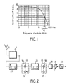
- This figure is a diagram relating to an A / D converter of the boom converter type (FLASH CONVERTER) and provides, on the ordinate, the effective number of bits (usable) at the converter output depending on the frequency of the input signal, plotted on the abscissa on a logarithmic scale.
- FLASH CONVERTER the boom converter type
- Filters are currently available, in particular SAW filters (surface wave filters) suitable for high frequencies (frequencies greater than or equal to the FI) but which we cannot adapt, at least for the time being, at lower frequencies which would be acceptable for an A / D converter.
- SAW filters surface wave filters
- the upper limit of the band is substantially constant in frequency and, in the first step, the signals of the adjacent channels higher than the signal considered are eliminated, the filtering during this first step being adapted to the maximum width of band for the signal considered, in the different possible TV standards.
- the two filters are constituted by filters SAW (surface wave filters).
- the bandwidth of these filters is at least equal to the maximum width of the band of IF signals different standards.
- the mixing circuit preferably includes a circuit multiplier, one input of which is connected to the output of the first filter and one of which other input is connected to the output of a local oscillator with fixed frequency, adjustable according to TV standard or other.
- a circuit multiplier one input of which is connected to the output of the first filter and one of which other input is connected to the output of a local oscillator with fixed frequency, adjustable according to TV standard or other.
- the adjustment of the fixed frequency of the local oscillator is ensured using a voltage electric.
- a frequency reducing circuit is provided at the outlet of the second filter, this reducing circuit comprising a multiplier including one input is connected to the output of the second filter and a local oscillator whose output is connected to another input of the multiplier; this local oscillator can have a frequency adjustable according to the standard of the TV channel selected corresponding to the signal to be processed.
- a low pass filter and a automatic gain control circuit are advantageously connected between the output of the frequency reducer and the input of the A / D converter.
- Frequency reduction is chosen so that the digitization by the A / D converter is done with precision high.
- the invention consists, apart from the arrangements set out above, in a number of other provisions which it will be more Explicit question below about an example of an embodiment described with references to the attached drawings, but which is in no way limiting.
- Figure 1 of these drawings is a diagram illustrating the variation of dynamic resolution of a conventional A / D converter, in function of the frequency plotted on the abscissa, while the effective number of bits at the output of the converter is plotted on the ordinate.
- Figure 2 is a diagram of a circuit according to the invention, allowing the implementation of the method of the invention.
- Figures 3A - 3E illustrate the different stages of the process to select the desired IF signal.
- Figures 4A - 4D are diagrams illustrating the frequency reduction of the desired IF signal.
- the circuit includes a conventional tuner 1 (or "tuner") whose input is connected to an antenna 2 receiving the signals to be processed.
- the device chord 1 has a local oscillator set to a frequency suitable for that of the signals picked up by the antenna 2 to create a beat and provide at the output of device 1 a signal whose frequency corresponds to the value standardized IF intermediate frequency, which can be around 40 MHz in the field of television.
- the signal available on the output of the tuning device 1 includes not only the desired signal S if N, corresponding to a determined channel, but also signals corresponding to channels adjacent to the desired signal.
- FIG. 3A shows a signal corresponding to the upper adjacent channel S if N + 1 and a signal corresponding to the lower adjacent channel S if N-1.
- the set of these three signals corresponds to an assumed bandwidth of the first IF signal for the example considered.
- the signal S if N is represented diagrammatically by a trapezoidal band 3, corresponding to the video band around the frequency fpc of the image carrier, and a narrower sound band 4, located just below the lower limit 5 of the band 3.
- the upper limit of band 3 is designated by 6.
- the upper limit 6 of band 3 of the desired signal S if N is substantially constant in frequency, from one television standard to another.
- the width L of the band 3 of the desired signal S if N varies substantially from one TV standard to another, so that the lower limit 5 of the band 3 of the desired signal varies in frequency according to the TV standard.
- a first bandpass filter 7 is chosen with an upper limit 8 corresponding in frequency to the substantially constant limit 6 of the band 3 of the signal S if N which it is desired to digitize.
- the characteristics of the passband, substantially in the form of rectangular window, of the filter 7 are illustrated by the diagram in FIG. 3B.
- the filter 7 is adapted to the different possible standards, that is to say that the filter 7 has a bandwidth of width K (see FIG. 3B) at least equal to the maximum bandwidth L of the different standards in the world, for the channel corresponding to the desired signal.
- the signals S if N + 1 of the adjacent channels greater than the limit 6 will be eliminated by the filter 7.
- the entire band 3 of the signal S if N desired will be transmitted, without being cut by the filter 7 since the bandwidth K of the latter is equal to or greater than the maximum bandwidth L of the various TV standards.
- the signal supplied on the output of filter 7 will consist not only of the desired signal S if N but also of a signal corresponding to the lower adjacent channel S if N-1 ..., since the bandwidth K of filter 7 is, for most standards, greater than the width L of the strip 3.
- the signal at the output of the filter 7 is represented in FIG. 3C; it includes the desired signal 3 (S if N) and part 9 of the lower adjacent signal S if N-1.
- the filter 7 is advantageously constituted by a SAW filter or commercially available surface wave filter operating perfectly for IF intermediate frequencies of the order of 40 MHz.
- SAW filters have a high quality / price ratio and constitute, currently, a particularly interesting solution for filtering.
- SAW filters do not work satisfactorily for frequencies clearly lower than IF frequencies.
- the output signal of the filter 7 is sent to the input of a mixer circuit 10 suitable for transposing the filtered IF signal, illustrated in FIG. 3C, in another range frequency, taking into account the signal standard S if N and its bandwidth.
- the mixer circuit 10 comprises a multiplier circuit 11 receiving on one input the output signals of the filter 7 and of which another input is driven by a local oscillator 12 at fixed frequency f Lo .
- the frequency of the oscillator 12 can be modified by means of a voltage U applied to the oscillator 12, and making it possible to adapt the fixed frequency fLo to the TV standard concerned.
- the transposition effect produced by the mixer circuit 9 is illustrated by the transition from Figure 3C to Figure 3D.
- This effect includes a frequency shift with a mirror effect causing a reversal the position of the channels as illustrated by the dashed arrows going from the Figure 3C in Figure 3D.
- the signal 9 adjacent to the lower limit of the signal to be processed in FIG. 3C has passed into 9a on the other side of the transposed signal 3a to be processed and has become adjacent to the upper limit 5a of the transposed signal 3a illustrated in FIG. 3D.
- the parameters of the mixer circuit 10 are chosen such that the upper limit 5a, indicated in FIG. 3D, of the band of the signal to be processed, corresponds to a substantially constant frequency, whatever the standard. This frequency may be the same as the frequency F1, corresponding to the upper limit of the signal S if N of FIG. 3A, or may be different.
- the global signal shown in solid lines in FIG. 3D, composed of the signal to be processed and a higher adjacent signal to be eliminated, is sent to the input of a second bandpass filter 13, advantageously also a SAW filter.
- the bandwidth of this second SAW filter is shown schematically by a substantially rectangular window 14, drawn in dashes in FIG. 3D.
- the upper limit 15 corresponds to the substantially constant value of the upper limit 5a of the signal to be processed transposed, taking into account possibly soundtrack 4a, so limit 15 can be slightly above limit 5a. But, anyway, the 5a limit remaining substantially constant, whatever the TV standard, it appears that the filter 13, with its limit 15 also constant, may be suitable whatever or the TV standard.
- the width Q of the bandwidth of the second SAW filter is chosen so that, whatever the TV standard, the signal to be processed is not altered by the second filter 13. In other words, we choose the bandwidth Q so that in any case, whatever the standard, the lower limit 16 of the bandwidth 14 of the second filter 13 is less than the limit lower 6a of the signal to be processed.
- the signal to be processed is obtained, represented on FIG. 3E, separated from the signals of the adjacent channels which were shown in Figure 3A.
- the form of the signal 3a obtained in FIG. 3E is symmetrical, with respect to an axis parallel to the ordinate axis, of the signal shown in Figure 3A, due to the mirror effect already explained.
- the selected IF signal represented in FIG. 3E, allows a good dynamic resolution since it is no longer cluttered with signals noise from adjacent channels.
- Such a signal can be obtained whatever either the TV standard without having to modify filters 7 and 13, the adaptation doing only at the level of the local oscillator 12, with the voltage U, to adjust the transposition effect corresponding to the passage in Figure 3C in Figure 3D.
- the signal obtained at the output of the filter 13 is at a frequency too high to be able to be scanned correctly by A / D converters available, at acceptable price, ensuring resolution sufficient dynamics.
- the outgoing signal 3a from the filter 13, schematically represented in FIG. 4A, is sent to the input of a converter circuit 17, to lower the frequency.
- This converter circuit 17 comprises a multiplier 18, one input of which is connected to the output of the filter 13 and of which another input is driven by the output signal of an oscillator 19 at local frequency f Lo1 .
- the frequency f Lo1 of this oscillator 19, illustrated in FIG. 4B, is constant, preferably adjustable as a function of the standard of the TV channel chosen.
- FIGS. 4A - 4D signals have been drawn in the left part of the figures corresponding to positive frequencies, and signals symmetrical about the ordinate axis for negative frequencies in a mathematical representation of signals.
- the frequency of the input signal of the converter 23 being relatively low, the sampling frequency may be higher than double the maximum frequency of the input signal, which is favorable for good resolution.
- the invention offers a wide field in the choice of frequency sampling and frequency of the local oscillator 19.
Landscapes
- Engineering & Computer Science (AREA)
- Multimedia (AREA)
- Signal Processing (AREA)
- Superheterodyne Receivers (AREA)
- Details Of Television Systems (AREA)
- Cable Transmission Systems, Equalization Of Radio And Reduction Of Echo (AREA)
Description
- dans une première étape, on élimine par filtrage les signaux des canaux adjacents à la limite sensiblement constante, en choisissant les caractéristiques du filtrage de manière telle que, quelle que soit la largeur de la bande du signal à traiter en fonction du standard, ce signal ne soit pas altéré par le filtrage du côté de sa limite variable en fréquence ;
- dans une seconde étape, on transpose en fréquence le signal à traiter, en fonction de sa largeur de bande, pour amener, dans le signal transposé, la limite variable de la bande du signal d'origine à une valeur sensiblement constante en fréquence,
- un premier filtre passe-bande dont une limite correspond en fréquence à la limite sensiblement constante de la bande du signal à traiter pour éliminer les signaux des canaux adjacents à cette limite du signal souhaité, ce filtre étant adapté à la largeur maximale de bande des différents standards, de manière à ne pas altérer le signal à traiter,quel que soit le standard;
- un circuit mélangeur pour transposer le signal FI filtré dans une autre gamme de fréquences, en tenant compte du standard de ce signal et de sa largeur de bande, et pour amener, dans le signal transposé, la limite variable du signal initial sur une valeur de fréquence sensiblement constante,
- et un deuxième filtre passe-bande dont une limite correspond, en fréquence, à la valeur de fréquence sensiblement constante du signal transposé, ce deuxième filtre étant adapté pour éliminer les signaux des canaux adjacents à la susdite valeur de fréquence constante du signal transposé, la largeur de la bande du filtre étant adaptée à la largeur maximale de bande des différents standards possibles.
Claims (10)
- Procédé pour numériser un signal de fréquence intermédiaire FI ayant une largeur de bande (L) qui peut varier d'un standard à l'autre, alors qu'une des limites (6) de cette bande est sensiblement constante en fréquence, caractérisé par le fait qu'avant de convertir le signal analogique en signal numérique, on élimine les signaux des canaux adjacents (Sif N + 1, SifN-1 ) à la bande (3) du signal à traiter selon les étapes suivantes:dans une première étape, on élimine par filtrage les signaux (SifN+1) des canaux adjacents à la limite(6) sensiblement constante les caractéristiques du filtrage étant telles que, quelle que soit la largeur (L) de la bande (3) du signal à traiter en fonction du standard, ce signal ne soit pas altéré par le filtrage du côté de sa limite variable en fréquence (5) ;dans une seconde étape, on transpose en fréquence le signal à traiter, en fonction de sa largeur de bande, pour amener, dans le signal transposé, la limite variable (5) de la bande (3) du signal d'origine à une valeur (5a) sensiblement constante en fréquence,et dans une troisième étape, on élimine par filtrage les signaux (9a) des canaux adjacents au signal transposé (3a), les caractéristiques du filtrage étant telles que, quelle que soit la largeur de la bande du signal à traiter, celui-ci ne soit pas altéré.
- Procédé selon la revendication 1 pour un signal FI dont la limite supérieure(6) de la bande est sensiblement constante en fréquence caractérisé par le fait que dans la première étape , on élimine les signaux (SifN+1) des canaux adjacents supérieurs au signal considéré (SifN), le filtrage lors de cette première étape étant adapté à la bande (L) de largeur maximale pour le signal considéré, dans les différents standards possibles TV.
- Procédé selon la revendication 1 ou 2, caractérisé par le fait que, pour réaliser ensuite la conversion en numérique du signal, on effectue, après les trois étapes mentionnées précédemment, une réduction de la fréquence du signal à traiter, avant son envoi sur l'entrée d'un convertisseur A/D.
- Circuit pour la numérisation d'un signal de fréquence intermédiaire FI ayant une entrée pour recevoir ce signal caractérisé par le fait qu'il comprend :un premier filtre passe-bande (7) dont une limite (8) correspond en fréquence à une limite sensiblement constante (6) de la bande (3) du signal à traiter pour éliminer les signaux (SifN + 1) des canaux adjacents à cette limite (6) du signal souhaité, ce filtre (7) étant adapté à la largeur (L) maximale de bande des différents standards, de manière à ne pas altérer le signal à traiter quel que soit le standard ;un circuit mélangeur (10) pour transposer le signal FI filtré dans une autre gamme de fréquences, en tenant compte du standard de ce signal et de sa largeur de bande, et pour amener, dans le signal transposé, la limite variable (5) du signal initial sur une valeur de fréquence sensiblement constante(5a),et un deuxième filtre passe-bande (13) dont une limite (15) correspond, en fréquence, à la valeur de fréquence sensiblement constante (5a) du signal transposé, ce deuxième filtre (13) étant adapté pour éliminer les signaux (9a) des canaux adjacents à la susdite valeur de fréquence constante du signal transposé, la largeur de la bande du filtre étant adaptée à la largeur maximale des différents standards possibles.
- Circuit selon la revendication 4 caractérisé par le fait que les deux filtres (7, 13) sont constitués par des filtres SAW ( filtres à ondes de surface).
- Circuit selon la revendication 4 ou 5 caractérisé par le fait que la largeur (K) de la bande passante des filtres (7, 13) est au moins égale à la largeur(L) maximale de la bande (3) des signaux FI des différents standards.
- Circuit selon l'une des revendications 4 à 6 caractérisé par le fait que le circuit mélangeur (10) comprend un circuit multiplieur (II 1) dont une entrée est reliée à la sortie du premier filtre (7) et dont une autre entrée est reliée à la sortie d'un oscillateur local(12) à fréquence fixe, réglable en fonction du standard TV ou autre.
- Circuit selon la revendication 7 caractérisé par le fait que le réglage de la fréquence fixe de l'oscillateur local (12) est fournie par une tension électrique (U).
- Circuit selon l'une des revendications 4 à 8 caractérisé par le fait qu'un circuit réducteur de fréquence (17) est prévu à une sortie du deuxième filtre (13), ce circuit réducteur (17) comprenant un multiplieur (18) dont une entrée est reliée à la sortie du deuxième filtre (13) et un oscillateur local (19) dont la sortie est reliée à une autre entrée du multiplieur (II 8).
- Circuit selon la revendication 9 caractérisé par le fait qu'un filtre passe-bas (20) et un circuit de commande automatique de gain (22) sont entreposés entre la sortie du réducteur de fréquence (II 7) et l'entrée d'un convertisseur A/D (23).
Applications Claiming Priority (2)
| Application Number | Priority Date | Filing Date | Title |
|---|---|---|---|
| FR9506111 | 1995-05-23 | ||
| FR9506111A FR2734681B1 (fr) | 1995-05-23 | 1995-05-23 | Procede pour numeriser un signal de frequence intermediaire fi, en particulier de television, et circuit pour la mise en oeuvre de ce procede |
Publications (3)
| Publication Number | Publication Date |
|---|---|
| EP0744865A2 EP0744865A2 (fr) | 1996-11-27 |
| EP0744865A3 EP0744865A3 (fr) | 1996-12-04 |
| EP0744865B1 true EP0744865B1 (fr) | 2001-07-11 |
Family
ID=9479280
Family Applications (1)
| Application Number | Title | Priority Date | Filing Date |
|---|---|---|---|
| EP96400880A Expired - Lifetime EP0744865B1 (fr) | 1995-05-23 | 1996-04-24 | Procédé pour numériser un signal de fréquence intermédiaire FI, en particulier de télévision, et circuit pour la mise en oeuvre de ce procédé |
Country Status (6)
| Country | Link |
|---|---|
| US (1) | US5748262A (fr) |
| EP (1) | EP0744865B1 (fr) |
| JP (1) | JP3910234B2 (fr) |
| DE (1) | DE69613763T2 (fr) |
| FR (1) | FR2734681B1 (fr) |
| ZA (1) | ZA963904B (fr) |
Families Citing this family (7)
| Publication number | Priority date | Publication date | Assignee | Title |
|---|---|---|---|---|
| JP3171052B2 (ja) * | 1995-04-13 | 2001-05-28 | 松下電器産業株式会社 | Catvコンバータ |
| DE19825455C2 (de) * | 1998-06-06 | 2000-04-06 | Micronas Intermetall Gmbh | Frequenzumsetzungseinrichtung für ein Fernsehsignalgemisch |
| GB2342238A (en) * | 1998-09-30 | 2000-04-05 | Sony Uk Ltd | Digital terrestrial TV tuner |
| US7203457B1 (en) | 1999-07-19 | 2007-04-10 | Thomson Licensing | Tuning system for achieving rapid signal acquisition for a digital satellite receiver |
| JP2001156665A (ja) * | 1999-11-24 | 2001-06-08 | Hitachi Ltd | 受信装置及びこれを用いたテレビジョン受像装置ならびに記録再生装置 |
| DE102004047424A1 (de) * | 2004-09-28 | 2006-04-06 | Micronas Gmbh | Schaltung und Verfahren zur Trägerrückgewinnung |
| DE102004048572A1 (de) * | 2004-10-04 | 2006-04-13 | Micronas Gmbh | Verfahren sowie Schaltungsanordnung zur Unterdrückung einer orthogonalen Störung |
Family Cites Families (5)
| Publication number | Priority date | Publication date | Assignee | Title |
|---|---|---|---|---|
| DE3114063A1 (de) * | 1981-04-07 | 1982-10-21 | Licentia Patent-Verwaltungs-Gmbh, 6000 Frankfurt | Empfangssystem |
| US4502078A (en) * | 1982-02-22 | 1985-02-26 | Rca Corporation | Digital television receivers |
| DE3743727A1 (de) * | 1987-12-23 | 1989-07-13 | Itt Ind Gmbh Deutsche | Fernsehempfangsteil mit digital arbeitenden stufen |
| DE4004631A1 (de) * | 1990-02-15 | 1991-08-22 | Philips Patentverwaltung | Fernsehempfangsteil |
| EP0629040A1 (fr) * | 1993-06-10 | 1994-12-14 | THOMSON multimedia | Méthode et démodulateur de démodulation à fréquence intermédiaire zéro d'un signal haute fréquence |
-
1995
- 1995-05-23 FR FR9506111A patent/FR2734681B1/fr not_active Expired - Fee Related
-
1996
- 1996-04-24 DE DE69613763T patent/DE69613763T2/de not_active Expired - Fee Related
- 1996-04-24 EP EP96400880A patent/EP0744865B1/fr not_active Expired - Lifetime
- 1996-05-14 US US08/645,765 patent/US5748262A/en not_active Expired - Fee Related
- 1996-05-16 ZA ZA963904A patent/ZA963904B/xx unknown
- 1996-05-22 JP JP12740696A patent/JP3910234B2/ja not_active Expired - Fee Related
Also Published As
| Publication number | Publication date |
|---|---|
| US5748262A (en) | 1998-05-05 |
| ZA963904B (en) | 1996-11-22 |
| JPH0946612A (ja) | 1997-02-14 |
| DE69613763D1 (de) | 2001-08-16 |
| DE69613763T2 (de) | 2001-10-25 |
| FR2734681B1 (fr) | 1997-07-04 |
| FR2734681A1 (fr) | 1996-11-29 |
| JP3910234B2 (ja) | 2007-04-25 |
| EP0744865A2 (fr) | 1996-11-27 |
| EP0744865A3 (fr) | 1996-12-04 |
Similar Documents
| Publication | Publication Date | Title |
|---|---|---|
| EP0941588B1 (fr) | Procede et dispositif de radiodiffusion mixte analogique et numerique d'emission radiophonique diffusee par un meme emetteur | |
| EP0616434A1 (fr) | Récepteur numérique à fréquence intermédiaire et procédé de filtrage en bande de base mis en oeuvre dans ce récepteur | |
| EP0624959B1 (fr) | Récepteur radio FM comprenant un circuit de suréchantillonnage | |
| BE897704A (fr) | Appareil a signaux analogiques et numeriques | |
| FR2702903A1 (fr) | Récepteur de signaux radiofréquences. | |
| EP0744865A2 (fr) | Procédé pour numériser un signal de fréquence intermédiaire FI, en particulier de télévision, et circuit pour la mise en oeuvre de ce procédé | |
| EP0169093B1 (fr) | Récepteur á démodulateur de fréquence pour système de télévision à multiplexage temporal | |
| EP1331749B1 (fr) | Transmission de signaux sur un cable coaxial | |
| DE69809384T2 (de) | Empfang modulierter träger mit asymmetrischen seitenbändern | |
| EP0150880B1 (fr) | Démodulateur à boucle à verrouillage de phase | |
| FR2517141A1 (fr) | Procede et dispositif de commande automatique de gain pour une transmission en modulation de frequence | |
| EP1039628A1 (fr) | Emetteur radiofréquence à fort degré d'intégration et avec annulation d'image, éventuellement auto-calibrée | |
| EP0749237A1 (fr) | Procédé de numérisation de signaux vidéo FI et dispositif pour mettre en oeuvre ce procédé | |
| FR2622752A1 (fr) | Circuit formant un filtre actif r.c. pour application coupe-bande | |
| FR2666709A1 (fr) | Ensemble de reglage de gain pour radiotelephone. | |
| CA1299679C (fr) | Filtre numerique fonctionnant a frequence intermediaire | |
| FR2810814A1 (fr) | Modulateur fm numerique a faible cout | |
| EP0740414B1 (fr) | Dispositif de retard programmable d'un signal analogique et antenne acoustique programmable correspondante | |
| FR2555847A1 (fr) | Filtre de preselection de canaux, notamment pour recepteur de television operant dans une bande etendue de frequences | |
| FR2853486A1 (fr) | Composant electronique permettant le decodage de signaux de television numerique ou par cable | |
| FR2586521A1 (fr) | Demodulateur de signaux modules en frequence | |
| EP0763899A1 (fr) | Procédé pour la numérisation de signaux à fréquence intermédiaire FI en particulier de signaux vidéo, et circuit pour la mise en oeuvre de ce procédé | |
| EP0681364A1 (fr) | Procédé et dispositif de réception d'au moins un signal d'entrée comprenant au moins une information codée | |
| EP0917790B1 (fr) | Demodulateur a circuit numerique de recuperation de porteuse et de rythme | |
| EP1130790B1 (fr) | Filtrage à l'émission pour un dispositif émetteur/récepteur de signaux radiofréquences. |
Legal Events
| Date | Code | Title | Description |
|---|---|---|---|
| PUAI | Public reference made under article 153(3) epc to a published international application that has entered the european phase |
Free format text: ORIGINAL CODE: 0009012 |
|
| PUAL | Search report despatched |
Free format text: ORIGINAL CODE: 0009013 |
|
| AK | Designated contracting states |
Kind code of ref document: A2 Designated state(s): DE FR GB IT |
|
| AK | Designated contracting states |
Kind code of ref document: A3 Designated state(s): DE FR GB IT |
|
| 17P | Request for examination filed |
Effective date: 19970516 |
|
| RAP1 | Party data changed (applicant data changed or rights of an application transferred) |
Owner name: THOMSON MULTIMEDIA |
|
| GRAG | Despatch of communication of intention to grant |
Free format text: ORIGINAL CODE: EPIDOS AGRA |
|
| 17Q | First examination report despatched |
Effective date: 19981221 |
|
| GRAG | Despatch of communication of intention to grant |
Free format text: ORIGINAL CODE: EPIDOS AGRA |
|
| GRAH | Despatch of communication of intention to grant a patent |
Free format text: ORIGINAL CODE: EPIDOS IGRA |
|
| GRAG | Despatch of communication of intention to grant |
Free format text: ORIGINAL CODE: EPIDOS AGRA |
|
| GRAG | Despatch of communication of intention to grant |
Free format text: ORIGINAL CODE: EPIDOS AGRA |
|
| GRAG | Despatch of communication of intention to grant |
Free format text: ORIGINAL CODE: EPIDOS AGRA |
|
| GRAH | Despatch of communication of intention to grant a patent |
Free format text: ORIGINAL CODE: EPIDOS IGRA |
|
| GRAH | Despatch of communication of intention to grant a patent |
Free format text: ORIGINAL CODE: EPIDOS IGRA |
|
| GRAA | (expected) grant |
Free format text: ORIGINAL CODE: 0009210 |
|
| AK | Designated contracting states |
Kind code of ref document: B1 Designated state(s): DE FR GB IT |
|
| GBT | Gb: translation of ep patent filed (gb section 77(6)(a)/1977) |
Effective date: 20010711 |
|
| REF | Corresponds to: |
Ref document number: 69613763 Country of ref document: DE Date of ref document: 20010816 |
|
| ITF | It: translation for a ep patent filed | ||
| REG | Reference to a national code |
Ref country code: GB Ref legal event code: 746 Effective date: 20011123 |
|
| REG | Reference to a national code |
Ref country code: GB Ref legal event code: IF02 |
|
| PLBE | No opposition filed within time limit |
Free format text: ORIGINAL CODE: 0009261 |
|
| STAA | Information on the status of an ep patent application or granted ep patent |
Free format text: STATUS: NO OPPOSITION FILED WITHIN TIME LIMIT |
|
| 26N | No opposition filed | ||
| REG | Reference to a national code |
Ref country code: FR Ref legal event code: ST |
|
| REG | Reference to a national code |
Ref country code: FR Ref legal event code: RN |
|
| REG | Reference to a national code |
Ref country code: FR Ref legal event code: FC |
|
| PGFP | Annual fee paid to national office [announced via postgrant information from national office to epo] |
Ref country code: DE Payment date: 20070424 Year of fee payment: 12 |
|
| PGFP | Annual fee paid to national office [announced via postgrant information from national office to epo] |
Ref country code: FR Payment date: 20070424 Year of fee payment: 12 |
|
| PGFP | Annual fee paid to national office [announced via postgrant information from national office to epo] |
Ref country code: GB Payment date: 20080326 Year of fee payment: 13 |
|
| PGFP | Annual fee paid to national office [announced via postgrant information from national office to epo] |
Ref country code: IT Payment date: 20080424 Year of fee payment: 13 |
|
| PG25 | Lapsed in a contracting state [announced via postgrant information from national office to epo] |
Ref country code: DE Free format text: LAPSE BECAUSE OF NON-PAYMENT OF DUE FEES Effective date: 20081101 |
|
| REG | Reference to a national code |
Ref country code: FR Ref legal event code: ST Effective date: 20081231 |
|
| PG25 | Lapsed in a contracting state [announced via postgrant information from national office to epo] |
Ref country code: FR Free format text: LAPSE BECAUSE OF NON-PAYMENT OF DUE FEES Effective date: 20080430 |
|
| GBPC | Gb: european patent ceased through non-payment of renewal fee |
Effective date: 20090424 |
|
| PG25 | Lapsed in a contracting state [announced via postgrant information from national office to epo] |
Ref country code: GB Free format text: LAPSE BECAUSE OF NON-PAYMENT OF DUE FEES Effective date: 20090424 |
|
| PG25 | Lapsed in a contracting state [announced via postgrant information from national office to epo] |
Ref country code: IT Free format text: LAPSE BECAUSE OF NON-PAYMENT OF DUE FEES Effective date: 20090424 |