EP0745729B1 - Plate-forme auto-élévatrice de forage ou d'exploitation pétrolière en mer - Google Patents
Plate-forme auto-élévatrice de forage ou d'exploitation pétrolière en mer Download PDFInfo
- Publication number
- EP0745729B1 EP0745729B1 EP96401122A EP96401122A EP0745729B1 EP 0745729 B1 EP0745729 B1 EP 0745729B1 EP 96401122 A EP96401122 A EP 96401122A EP 96401122 A EP96401122 A EP 96401122A EP 0745729 B1 EP0745729 B1 EP 0745729B1
- Authority
- EP
- European Patent Office
- Prior art keywords
- chain
- legs
- platform according
- leg
- hull
- Prior art date
- Legal status (The legal status is an assumption and is not a legal conclusion. Google has not performed a legal analysis and makes no representation as to the accuracy of the status listed.)
- Expired - Lifetime
Links
- 238000005553 drilling Methods 0.000 title claims description 11
- 230000003028 elevating effect Effects 0.000 title 1
- 230000007246 mechanism Effects 0.000 claims description 13
- XLYOFNOQVPJJNP-UHFFFAOYSA-N water Substances O XLYOFNOQVPJJNP-UHFFFAOYSA-N 0.000 claims description 11
- 239000003638 chemical reducing agent Substances 0.000 claims description 3
- 230000000712 assembly Effects 0.000 claims 1
- 238000000429 assembly Methods 0.000 claims 1
- 238000005188 flotation Methods 0.000 description 4
- 238000011084 recovery Methods 0.000 description 3
- 238000009434 installation Methods 0.000 description 2
- 238000004519 manufacturing process Methods 0.000 description 2
- 239000002184 metal Substances 0.000 description 2
- 235000005921 Cynara humilis Nutrition 0.000 description 1
- 240000002228 Cynara humilis Species 0.000 description 1
- 230000003292 diminished effect Effects 0.000 description 1
- 238000006073 displacement reaction Methods 0.000 description 1
- 230000000694 effects Effects 0.000 description 1
- 230000002650 habitual effect Effects 0.000 description 1
- 238000003754 machining Methods 0.000 description 1
- 210000000056 organ Anatomy 0.000 description 1
- 239000013641 positive control Substances 0.000 description 1
- 230000000284 resting effect Effects 0.000 description 1
- 239000003351 stiffener Substances 0.000 description 1
Images


Classifications
-
- E—FIXED CONSTRUCTIONS
- E21—EARTH OR ROCK DRILLING; MINING
- E21B—EARTH OR ROCK DRILLING; OBTAINING OIL, GAS, WATER, SOLUBLE OR MELTABLE MATERIALS OR A SLURRY OF MINERALS FROM WELLS
- E21B15/00—Supports for the drilling machine, e.g. derricks or masts
-
- E—FIXED CONSTRUCTIONS
- E02—HYDRAULIC ENGINEERING; FOUNDATIONS; SOIL SHIFTING
- E02B—HYDRAULIC ENGINEERING
- E02B17/00—Artificial islands mounted on piles or like supports, e.g. platforms on raisable legs or offshore constructions; Construction methods therefor
- E02B17/02—Artificial islands mounted on piles or like supports, e.g. platforms on raisable legs or offshore constructions; Construction methods therefor placed by lowering the supporting construction to the bottom, e.g. with subsequent fixing thereto
- E02B17/021—Artificial islands mounted on piles or like supports, e.g. platforms on raisable legs or offshore constructions; Construction methods therefor placed by lowering the supporting construction to the bottom, e.g. with subsequent fixing thereto with relative movement between supporting construction and platform
-
- E—FIXED CONSTRUCTIONS
- E02—HYDRAULIC ENGINEERING; FOUNDATIONS; SOIL SHIFTING
- E02B—HYDRAULIC ENGINEERING
- E02B17/00—Artificial islands mounted on piles or like supports, e.g. platforms on raisable legs or offshore constructions; Construction methods therefor
- E02B17/04—Equipment specially adapted for raising, lowering, or immobilising the working platform relative to the supporting construction
- E02B17/08—Equipment specially adapted for raising, lowering, or immobilising the working platform relative to the supporting construction for raising or lowering
- E02B17/0818—Equipment specially adapted for raising, lowering, or immobilising the working platform relative to the supporting construction for raising or lowering with racks actuated by pinions
-
- E—FIXED CONSTRUCTIONS
- E02—HYDRAULIC ENGINEERING; FOUNDATIONS; SOIL SHIFTING
- E02B—HYDRAULIC ENGINEERING
- E02B17/00—Artificial islands mounted on piles or like supports, e.g. platforms on raisable legs or offshore constructions; Construction methods therefor
- E02B2017/0039—Methods for placing the offshore structure
- E02B2017/0043—Placing the offshore structure on a pre-installed foundation structure
-
- E—FIXED CONSTRUCTIONS
- E02—HYDRAULIC ENGINEERING; FOUNDATIONS; SOIL SHIFTING
- E02B—HYDRAULIC ENGINEERING
- E02B17/00—Artificial islands mounted on piles or like supports, e.g. platforms on raisable legs or offshore constructions; Construction methods therefor
- E02B2017/0056—Platforms with supporting legs
- E02B2017/006—Platforms with supporting legs with lattice style supporting legs
-
- E—FIXED CONSTRUCTIONS
- E02—HYDRAULIC ENGINEERING; FOUNDATIONS; SOIL SHIFTING
- E02B—HYDRAULIC ENGINEERING
- E02B17/00—Artificial islands mounted on piles or like supports, e.g. platforms on raisable legs or offshore constructions; Construction methods therefor
- E02B2017/0056—Platforms with supporting legs
- E02B2017/0073—Details of sea bottom engaging footing
- E02B2017/0082—Spudcans, skirts or extended feet
Definitions
- the subject of the present invention is a platform self-elevating drilling or offshore operation.
- Platforms of this type include usually legs resting on the seabed and a hull mounted movable and adjustable in height the along the legs, said shell supporting in particular a drill floor and a drill tower.
- the whole platform is brought in flotation to the drilling or operating site, and the legs are lowered in contact with a structure bearing or the seabed, then taking support from the legs, the hull is hoisted above sea level up to an altitude which puts it out of the reach of higher waves.
- the shell is therefore movable along the legs of the platform by means of drive mechanisms housed in a structure well known to specialists under the name of "jack-house”.
- These drive mechanisms include at least two opposite sets each formed by a motor associated with at least one reduction gear driven by a shaft an output pinion cooperating with racks opposite and mounted on the legs of the platform.
- each leg is provided at its lower part of a foot, for example square or hexagonal which comes to rest directly on the bottom marine or on the supporting structure.
- the racks extend practically over full length of legs and serve in their most large portion to hold these legs until installation of the platform on the operating site or drilling.
- the racks serve, through gables, to slow down the descent of the legs until time each foot touches the seabed or the load-bearing structure.
- each leg is made up of vertical members, three or three four, linked together by a trellis of metal beams.
- Each frame is made up of sections welded end to end and each formed of a on the one hand by a rectangular plate and on the other by welded half-shell stiffeners each on one of the main faces of said plate.
- the rectangular plates feature on their lateral face of the teeth which form the diametrically opposite racks, intended for cooperate with the output gears of the mechanisms drive.
- a self-elevating drilling platform of the type comprising a movable mounted shell, between a flotation position and an operating position out of the water, on load-bearing legs by means of drive mechanisms comprising, per leg, two opposite sets each formed by a motor associated with a reduction gear driven by a shaft an output pinion cooperating with racks mounted on the legs.
- the legs are movable between a raised position and a position supported on a supporting structure or on the seabed.
- Each rack is provided on a corresponding leg length required for move the hull between the float position and the operating position.
- the invention aims to remedy the disadvantages previously mentioned, by creating a oil drilling or exploitation platform in sea whose weight and hydrodynamic drag of legs are diminished.
- the subject of the invention is therefore a platform self-elevating drilling or operating oil at sea, of the type comprising a hull mounted movable, between a floating position and a operating position above water, on legs load-bearing by means of drive mechanisms comprising at least two opposite sets each formed by a motor associated with at least one driving reduction gear by a shaft an output pinion cooperating with opposite racks mounted on the legs, said legs being movable between a position raised and a position supported on a structure carrier or the seabed, characterized in that each rack extends over a height between 20 and 30% of the total height of the corresponding leg for move the hull between the buoyancy position and the operating position and in that it includes means of controlling the descent of each leg to the supporting structure or to the seabed formed by at least one chain cooperating with an organ gear mounted on the drive shaft of a output pinion of a set, each chain comprising a first end connected to the foot of the leg corresponding and a second end connected to the hull, the length of said chain being sufficient for the descent
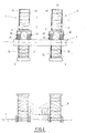
- FIGs. 1 to 3 there is shown schematically a self-elevating drilling platform or offshore oil exploitation including a hull 1 movable and adjustable in position on legs vertical 2.
- Each of the vertical legs 2 has, in the present case, a square section, and it is made up of four members 3 connected together by a lattice 4 of metal tubes.
- the vertical legs 2 can also presented a triangular or circular section.
- Each vertical leg 2 ends at its lower part by a foot 5 which, in the present example, is square, but can be square hexagonal.
- the shell 1 is also equipped with operating equipment and premises habitual housing as well as a non-drilling tower represented.
- the platform is brought into the waterline on the site, i.e. that hull 1 floats on water and most of it legs 2 is out of the water.
- legs 2 went down so that the 5 feet rest on a structure carrier 6 placed on the seabed 7 or supported directly on the seabed 7 and, in a second time, hull 1 is hoisted above the level of the sea, up to an altitude that puts it out of reach higher waves, as shown in Fig. 2.
- the movement of the legs 2 between the position raised and the position supported on the supporting structure 6 or on the seabed 7 is provided by means of control of the descent of each leg 2 and movement of hull 1 between the buoyancy position and the operating position above water is ensured by drive mechanisms.
- the mechanisms 10 are provided at each members 3 of the vertical legs 2 and are housed in a structure well known to specialists under the name "Jack-house”.
- Each drive mechanism 10 is composed at least two sets 11 opposite and each formed by a motor 12 associated with a reduction gear 13.
- each drive mechanism 10 is consists of three pairs of sets 11 superimposed one above the other, the number of pairs of sets superimposed depending on the mass of the hull 1 to move.
- Motor 12 and reducer 13 of each together 11 drive by a shaft 14 a pinion of outlet 15 which cooperates with a rack 16 provided on the corresponding member 3.
- each member 3 of each of the legs 2 has two opposite racks 16 which extend only over a specified length said legs 2.
- the pinions 15 and the racks 16 have, in the platform according to the invention, only for the purpose of ensuring the displacement of the shell 1 between the flotation position (Fig. 1) and the operating position out of the water (Fig. 2).
- each rack 16 is arranged at the upper part of the members 3 of legs 2, as shown in Figs. 1 and 2.
- the racks 16 extend over a height between 20 and 30% of the total height of legs 2.
- the racks 16 extend over a height of 29 meters which represents approximately 22% of total leg height 2.
- the platform according to the invention is equipped with means 20 for controlling the descent of each leg 2.
- Each leg 2 is equipped with four means to control the descent of the corresponding leg 2 and each means consists of two chains 21 which cooperate with the lower assembly 11 of each mechanism 10.
- each leg 2 is associated with eight chains 21 for the descent of the corresponding leg.
- Each chain 21 has a first end 21a detachably connected to the corresponding foot 5 and a second end 21b connected to the shell 1.
- each chain 21 cooperates with a engagement member 22 mounted on the drive shaft 14 of an output pinion 15.
- each chain is sufficient to allow the descent of the corresponding leg 2 from its raised position to its position by pressing the supporting structure 6 or on the seabed 7.
- Each engagement member 22 cooperating with a chain 21 is constituted for example by a wheel toothed or by a capstan wheel.
- each engagement member 22 is greater than the diameter of the output pinion 15 of such so that the frame rate of each channel 21 is greater than the developed tangential speed of pinions 15 on the racks 16.
- each chain 21 is connected to the foot 5 via a hook 25 which is itself connected to the foot 5 by a elastic connecting member 26 constituted for example by a superposition of elastic washers or by any other suitable device.
- each chain 21 is therefore detachably connected to the corresponding foot 5 and is connected to the hull 1 by a recovery line 27 of which a first end 27a is connected to the end 21a of the corresponding chain and of which a second end 27b is fixed on the drum of a winch 28 allowing to go up the corresponding chain 21, as we will see later.
- each chain 21 can be detached from the hook 25 for example by a robot or by any other appropriate means.
- each foot 5 of the platform constitutes a buoyancy element making it possible to reduce the speed of descent of legs 2 and decrease the weight of these legs 2 as and when their descent.
- the installation of the platform on the structure carrier 6 or on the seabed 7 is carried out from the next way.
- motors 12 and reducers 13 drive in rotation the shafts 14, the pinions 15 and the members mesh 22 which has the effect of causing chains 21 and cause the legs to descend 2 by scrolling channels 21.
- Chains 21 unfold gradually and the length of these chains is sufficient for the lowering of the legs 2 to the supporting structure 6 or to the seabed.
Landscapes
- Engineering & Computer Science (AREA)
- General Engineering & Computer Science (AREA)
- Mechanical Engineering (AREA)
- Civil Engineering (AREA)
- Structural Engineering (AREA)
- Life Sciences & Earth Sciences (AREA)
- Geology (AREA)
- Mining & Mineral Resources (AREA)
- Physics & Mathematics (AREA)
- Environmental & Geological Engineering (AREA)
- Fluid Mechanics (AREA)
- General Life Sciences & Earth Sciences (AREA)
- Geochemistry & Mineralogy (AREA)
- Earth Drilling (AREA)
Description
- chaque jambe comporte à sa partie inférieure un pied formant un élément de flottabilité,
- chaque crémaillère est disposée à la partie supérieure de la jambe correspondante,
- la vitesse de défilement de chaque chaíne est supérieure à la vitesse tangentielle développée des pignons sur les crémaillères,
- chaque organe d'engrènement est formé par une roue dentée ou une roue de cabestan,
- la première extrémité de chaque chaíne est reliée au pied de la jambe correspondante par un organe de liaison élastique,
- la première extrémité de chaque chaíne est détachable de l'organe de liaison élastique,
- la première extrémité de chaque chaíne est raccordée à la coque par une ligne de récupération de la chaíne correspondante.
- la Fig. 1 est une vue schématique en élévation d'une plate-forme auto-élévatrice selon l'invention, en configuration de descente des jambes,
- la Fig. 2 est une vue schématique en élévation d'une plate-forme auto-élévatrice selon l'invention, en configuration d'exploitation,
- la Fig. 3 est une vue de dessus de la plate-forme selon l'invention,
- la Fig. 4 est une vue schématique à plus grande échelle d'une membrure d'une jambe de la plate-forme selon l'invention,
- la Fig. 5 est une vue en coupe selon la ligne 5-5 de la Fig. 4,
- la Fig. 6 est une vue en coupe selon la ligne 6-6 de la Fig. 4,
- la Fig. 7 est une vue schématique en coupe montrant l'accrochage d'une chaíne sur un pied d'une jambe de la plate-forme selon l'invention.
Claims (9)
- Plate-forme auto-élévatrice de forage ou d'exploitation pétrolière en mer, du type comprenant une coque (1) montée déplaçable, entre une position de flottaison et une position d'exploitation hors de l'eau, sur des jambes porteuses (2) au moyen de mécanismes (10) d'entraínement comportant au moins deux ensembles opposés (11) formés chacun par un moteur (12) associé à au moins un réducteur (13) entraínant par un arbre (14) un pignon de sortie (15) coopérant avec des crémaillères (16) opposées et montées sur les jambes (2), lesdites jambes (2) étant déplaçables entre une position relevée et une position en appui sur une structure porteuse (6) ou sur le fond marin (7), caractérisée en ce que chaque crémaillère (16) s'étend sur une hauteur comprise entre 20 et 30% de la hauteur totale de la jambe (2) correspondante pour déplacer la coque (1) entre la position de flottaison et la position d'exploitation et en ce qu'elle comporte des moyens (20) de contrôle de la descente de chaque jambe (2) jusqu'à la structure porteuse (6) ou jusqu'au fond marin (7) formés par au moins une chaíne (21) coopérant avec un organe d'engrènement (22) monté sur l'arbre d'entraínement (14) d'un pignon de sortie (15) d'un ensemble (11), chaque chaíne (21) comportant une première extrémité (21a) reliée au pied (5) de la jambe (2) correspondante et une seconde extrémité (21b) reliée à la coque (1), la longueur de ladite chaíne (21) étant suffisante pour la descente de la jambe (2) correspondante jusqu'à la structure porteuse (6) ou jusqu'au fond marin (7).
- Plate-forme selon la revendication 1, caractérisée en ce que chaque jambe (2) comporte à sa partie inférieure un pied (5) formant un élément de flottabilité.
- Plate-forme selon la revendication 1, caractérisée en ce que chaque crémaillère (16) est disposée à la partie supérieure de la jambe (2) correspondante.
- Plate-forme selon la revendication 1, caractérisée en ce que la vitesse de défilement de chaque chaíne (21) est supérieure à la vitesse tangentielle développée des pignons (15) sur les crémaillères (16).
- Plate-forme selon la revendication 1, caractérisée en ce que chaque organe d'engrènement (22) est formé par une roue dentée.
- Plate-forme selon la revendication 1, caractérisée en ce que chaque organe d'engrènement (22) est formé par une roue de cabestan.
- Plate-forme selon l'une quelconque des revendications 1 à 4, caractérisée en ce que la première extrémité (21a) de chaque chaíne (21) est reliée au pied (5) de la jambe (2) correspondante par un organe de liaison élastique (26).
- Plate-forme selon la revendication 7, caractérisée en ce que la première extrémité (21a) de chaque chaíne (21) est détachable de l'organe de liaison élastique (26).
- Plate-forme selon l'une quelconque des revendications précédentes, caractérisée en ce que la première extrémité (21a) de chaque chaíne (21) est raccordée à la coque (1) par une ligne (27) de récupération de la chaíne (21) correspondante.
Applications Claiming Priority (2)
| Application Number | Priority Date | Filing Date | Title |
|---|---|---|---|
| FR9506604A FR2734851B1 (fr) | 1995-06-02 | 1995-06-02 | Plate-forme auto-elevatrice de forage ou d'exploitation petroliere en mer. |
| FR9506604 | 1995-06-02 |
Publications (2)
| Publication Number | Publication Date |
|---|---|
| EP0745729A1 EP0745729A1 (fr) | 1996-12-04 |
| EP0745729B1 true EP0745729B1 (fr) | 2003-03-26 |
Family
ID=9479629
Family Applications (1)
| Application Number | Title | Priority Date | Filing Date |
|---|---|---|---|
| EP96401122A Expired - Lifetime EP0745729B1 (fr) | 1995-06-02 | 1996-05-23 | Plate-forme auto-élévatrice de forage ou d'exploitation pétrolière en mer |
Country Status (8)
| Country | Link |
|---|---|
| US (1) | US5833396A (fr) |
| EP (1) | EP0745729B1 (fr) |
| JP (1) | JP3754495B2 (fr) |
| KR (1) | KR100412012B1 (fr) |
| ES (1) | ES2194085T3 (fr) |
| FR (1) | FR2734851B1 (fr) |
| NO (1) | NO312207B1 (fr) |
| SG (1) | SG54338A1 (fr) |
Cited By (1)
| Publication number | Priority date | Publication date | Assignee | Title |
|---|---|---|---|---|
| CN103089231A (zh) * | 2011-10-27 | 2013-05-08 | 中集船舶海洋工程设计研究院有限公司 | 自升式海洋平台的驱动系统 |
Families Citing this family (17)
| Publication number | Priority date | Publication date | Assignee | Title |
|---|---|---|---|---|
| FR2759400B1 (fr) * | 1997-02-07 | 1999-04-23 | Schlumberger Services Petrol | Plate-forme de forage petrolier du type "jack-up" ou a piliers elevateurs a cremaillere, a elevation independante pour chaque membrure de chaque pilier |
| FR2760474B1 (fr) * | 1997-03-07 | 1999-05-28 | Technip Geoproduction | Procede d'assemblage de troncons de jambes de support d'une plate-forme petroliere |
| EP0942102B1 (fr) * | 1998-03-11 | 2004-09-01 | Technip France | Plate-forme auto-élévatrice à réservoir immergé et procédés de mise en place et de relevage du réservoir |
| US6200069B1 (en) | 1999-07-20 | 2001-03-13 | George Austin Miller | Hovercraft work platform |
| FR2876124B1 (fr) * | 2004-10-06 | 2007-04-13 | Technip France Sa | Plate-forme d'exploitation en mer et procedes d'installation sur un site d'exploitation en mer d'une telle plate-forme |
| CA2596676C (fr) * | 2005-02-04 | 2013-04-16 | Technip France | Systeme de verrouillage complementaire des jambes sur un pont d'une plate-forme d'exploitation en mer et procedes de pose d'un tel systeme de verrouillage |
| FR2913241B1 (fr) * | 2007-03-01 | 2009-06-05 | Technip France Sa | Plate-forme auto-elevatrice de tres grandes dimensions pour le traitement de gaz de petrole en mer et procede d'assemblage et d'installation d'une telle plate-forme. |
| KR101721841B1 (ko) | 2007-03-20 | 2017-03-31 | 지멘스 에이에스 | 잭-업 플랫폼의 지지 레그의 이동을 제어하기 위한 구동 제어 시스템 |
| US20090090191A1 (en) * | 2007-10-05 | 2009-04-09 | Bernardino Lenders | Methods and structures for monitoring offshore platform supports |
| US8336388B2 (en) | 2007-10-05 | 2012-12-25 | National Oilwell Varco, L.P. | Methods and structures for monitoring offshore platform supports |
| CN101214846A (zh) * | 2007-12-29 | 2008-07-09 | 汪东君 | 一种用于自行车踏板拆装的装置及一步控制拆装的组件 |
| FR2963367B1 (fr) * | 2010-07-30 | 2014-01-24 | Cie Engrenages Et Reducteurs Messian Durand | Ascenseur a bateau |
| NL2005755C2 (en) * | 2010-11-25 | 2012-05-29 | Cobus Beheer B V | Floating marine structure. |
| CN105035260B (zh) * | 2015-05-19 | 2017-06-16 | 中国海洋石油总公司 | 利用双船浮托整体拆除海上弃置平台上部组块的方法 |
| CN105603954B (zh) * | 2016-03-18 | 2017-11-24 | 中国石油集团渤海石油装备制造有限公司 | 一种用于自升式钻井平台桩腿转向滑移接桩的装置 |
| CN106373449B (zh) * | 2016-10-18 | 2019-01-29 | 浙江海洋大学 | 一种模拟海上作业工况的海洋工程试验平台装置 |
| FR3103000B1 (fr) | 2019-11-13 | 2022-08-05 | Technip France | Installation pour supporter une plate-forme auto-élévatrice de forage ou d’exploitation pétrolière |
Family Cites Families (14)
| Publication number | Priority date | Publication date | Assignee | Title |
|---|---|---|---|---|
| US516032A (en) * | 1894-03-06 | Submarine-drilling apparatus | ||
| US3011467A (en) * | 1957-07-22 | 1961-12-05 | Robert G Letourneau | Mobile sea platform |
| US3044269A (en) * | 1957-07-22 | 1962-07-17 | Tourneau Robert G Le | Mobile sea platform |
| US3014346A (en) * | 1957-09-10 | 1961-12-26 | Jersey Prod Res Co | Method and means for raising and lowering a platform |
| US2996284A (en) * | 1958-12-15 | 1961-08-15 | Welborn Jack Vernon | Shinning jack |
| GB1169262A (en) * | 1965-08-10 | 1969-11-05 | Vickers Ltd | Improved floatable vessel |
| US3435621A (en) * | 1966-07-26 | 1969-04-01 | American Mach & Foundry | Jacking system for offshore platforms |
| US3946684A (en) * | 1971-01-18 | 1976-03-30 | Sumner Maurice N | Semi-submersible jackup apparatus |
| NL7508843A (nl) * | 1974-08-12 | 1976-02-16 | Strabag Bau Ag | Platform voor het werken op zee. |
| DE2549000A1 (de) * | 1975-11-03 | 1977-05-12 | Strabag Bau Ag | Plattform fuer arbeiten im meer |
| FI802781A7 (fi) * | 1979-09-07 | 1981-01-01 | Brown & Ass James G | Merilavan tukirakenne. |
| DE3112702A1 (de) * | 1981-03-31 | 1982-10-07 | Deutsche Babcock Anlagen Ag, 4200 Oberhausen | Hubeinrichtung fuer eine offshore-konstruktion |
| FR2607165B1 (fr) * | 1986-11-26 | 1990-07-20 | Technip Geoproduction | Dispositif de suspension des jambes de support de plate-forme petroliere auto-elevatrice |
| FR2643401B1 (fr) * | 1989-02-22 | 1995-05-05 | Brissonneau & Lotz | Mecanismes de manoeuvre de plateformes de forage auto-elevatrices, et plateformes munies de ces mecanismes |
-
1995
- 1995-06-02 FR FR9506604A patent/FR2734851B1/fr not_active Expired - Lifetime
-
1996
- 1996-05-23 ES ES96401122T patent/ES2194085T3/es not_active Expired - Lifetime
- 1996-05-23 EP EP96401122A patent/EP0745729B1/fr not_active Expired - Lifetime
- 1996-05-30 NO NO19962206A patent/NO312207B1/no not_active IP Right Cessation
- 1996-06-01 KR KR1019960019482A patent/KR100412012B1/ko not_active Expired - Lifetime
- 1996-06-01 SG SG1996009944A patent/SG54338A1/en unknown
- 1996-06-03 US US08/657,299 patent/US5833396A/en not_active Expired - Lifetime
- 1996-06-03 JP JP14002696A patent/JP3754495B2/ja not_active Expired - Fee Related
Cited By (2)
| Publication number | Priority date | Publication date | Assignee | Title |
|---|---|---|---|---|
| CN103089231A (zh) * | 2011-10-27 | 2013-05-08 | 中集船舶海洋工程设计研究院有限公司 | 自升式海洋平台的驱动系统 |
| CN103089231B (zh) * | 2011-10-27 | 2015-07-01 | 中集船舶海洋工程设计研究院有限公司 | 自升式海洋平台的驱动系统 |
Also Published As
| Publication number | Publication date |
|---|---|
| EP0745729A1 (fr) | 1996-12-04 |
| KR970001847A (ko) | 1997-01-24 |
| SG54338A1 (en) | 1998-11-16 |
| KR100412012B1 (ko) | 2004-04-09 |
| NO962206D0 (no) | 1996-05-30 |
| ES2194085T3 (es) | 2003-11-16 |
| US5833396A (en) | 1998-11-10 |
| JP3754495B2 (ja) | 2006-03-15 |
| FR2734851A1 (fr) | 1996-12-06 |
| JPH09100525A (ja) | 1997-04-15 |
| NO312207B1 (no) | 2002-04-08 |
| NO962206L (no) | 1996-12-03 |
| FR2734851B1 (fr) | 1999-03-05 |
Similar Documents
| Publication | Publication Date | Title |
|---|---|---|
| FR2734851A1 (fr) | Plate-forme auto-elevatrice de forage ou d'exploitation petroliere en mer. | |
| EP1798342B1 (fr) | Dispositif de démentèlement et de transport d'une plate-forme pétrolière | |
| EP0964102B1 (fr) | Dispositif de transport et de pose d'un pont d'une plate-forme pétrolière d'exploitation en mer | |
| EP1487693B1 (fr) | Structure de transport, d'installation et de demantelement d'un pont d'une plate-forme petroliere fixe et procede de mise en oeuvre d'une telle structure | |
| EP0090006B1 (fr) | Dispositif flottant et procede de levage et de transport de charge | |
| CA2280399C (fr) | Installation d'exploitation d'un gisement en mer et procede d'implantation d'une colonne montante | |
| FR2560280A1 (fr) | Tour pour le forage et l'entretien de puits de petrole ou de gaz | |
| EP2091808A1 (fr) | Structure de transport, d'installation et de demantelement d'un pont d'une plate-forme petroliere et procedes de mise en oeuvre d'une telle structure | |
| EP0942102B1 (fr) | Plate-forme auto-élévatrice à réservoir immergé et procédés de mise en place et de relevage du réservoir | |
| EP1348867B1 (fr) | Installation de production éolienne d'électricité en mer, ainsi que procédé de construction et de mise en place d'une telle installation | |
| EP0863260B1 (fr) | Procédé d'assemblage de tronçons de jambes de support d'une plate-forme pétrolière | |
| EP0441673B1 (fr) | Plate-forme pétrolière auto-élévatrice | |
| FR2492029A1 (fr) | Bloc pignons autoalignant et autobasculant pour patte de plate-forme auto-elevatrice | |
| EP0014661B1 (fr) | Dispositif pour l'installation d'un bloc formant réacteur nucléaire dans un navire | |
| US5797703A (en) | Elevating unit for use with jack-up rig | |
| CA1281555C (fr) | Plate-forme semi-submersible, notamment pour la recherche et/ou l'exploitation de gisements sous- marins en mers froides | |
| BE887882A (fr) | Structure pour supporter un appareillage au-dessus du fond d'une masse d'eau | |
| FR2713588A1 (fr) | Plate-forme auto-élévatrice d'exploitation pétrolière en grande profondeur. | |
| EP0056753B1 (fr) | Dispositif élévateur pour plate-forme marine auto-élévatrice | |
| FR2876123A1 (fr) | Procede d'installation des jambes sur un pont d'une plate-forme d'exploitation en mer. | |
| WO1979000016A1 (fr) | Procedure de mise en place d'une structure support de torchere pour plate-forme petroliere | |
| WO2021094191A1 (fr) | Installation pour supporter une plate-forme auto-elevatrice | |
| FR2468542A1 (fr) | Perfectionnements aux derricks marins | |
| FR2565290A1 (fr) | Procede et dispositif de creusement de puits | |
| CA1273965A (fr) | Procede et dispositif de creusement de puits |
Legal Events
| Date | Code | Title | Description |
|---|---|---|---|
| PUAI | Public reference made under article 153(3) epc to a published international application that has entered the european phase |
Free format text: ORIGINAL CODE: 0009012 |
|
| AK | Designated contracting states |
Kind code of ref document: A1 Designated state(s): ES FI GB IT |
|
| 17P | Request for examination filed |
Effective date: 19970509 |
|
| RAP1 | Party data changed (applicant data changed or rights of an application transferred) |
Owner name: TECHNIP FRANCE |
|
| 17Q | First examination report despatched |
Effective date: 20010214 |
|
| GRAH | Despatch of communication of intention to grant a patent |
Free format text: ORIGINAL CODE: EPIDOS IGRA |
|
| GRAH | Despatch of communication of intention to grant a patent |
Free format text: ORIGINAL CODE: EPIDOS IGRA |
|
| GRAA | (expected) grant |
Free format text: ORIGINAL CODE: 0009210 |
|
| AK | Designated contracting states |
Designated state(s): ES FI GB IT |
|
| REG | Reference to a national code |
Ref country code: GB Ref legal event code: FG4D Free format text: NOT ENGLISH |
|
| GBT | Gb: translation of ep patent filed (gb section 77(6)(a)/1977) |
Effective date: 20030715 |
|
| REG | Reference to a national code |
Ref country code: ES Ref legal event code: FG2A Ref document number: 2194085 Country of ref document: ES Kind code of ref document: T3 |
|
| PLBE | No opposition filed within time limit |
Free format text: ORIGINAL CODE: 0009261 |
|
| STAA | Information on the status of an ep patent application or granted ep patent |
Free format text: STATUS: NO OPPOSITION FILED WITHIN TIME LIMIT |
|
| 26N | No opposition filed |
Effective date: 20031230 |
|
| PGFP | Annual fee paid to national office [announced via postgrant information from national office to epo] |
Ref country code: IT Payment date: 20090527 Year of fee payment: 14 |
|
| PG25 | Lapsed in a contracting state [announced via postgrant information from national office to epo] |
Ref country code: IT Free format text: LAPSE BECAUSE OF NON-PAYMENT OF DUE FEES Effective date: 20100523 |
|
| PGFP | Annual fee paid to national office [announced via postgrant information from national office to epo] |
Ref country code: FI Payment date: 20150420 Year of fee payment: 20 Ref country code: GB Payment date: 20150518 Year of fee payment: 20 Ref country code: ES Payment date: 20150525 Year of fee payment: 20 |
|
| REG | Reference to a national code |
Ref country code: GB Ref legal event code: PE20 Expiry date: 20160522 |
|
| PG25 | Lapsed in a contracting state [announced via postgrant information from national office to epo] |
Ref country code: GB Free format text: LAPSE BECAUSE OF EXPIRATION OF PROTECTION Effective date: 20160522 |
|
| REG | Reference to a national code |
Ref country code: ES Ref legal event code: FD2A Effective date: 20160830 |
|
| PG25 | Lapsed in a contracting state [announced via postgrant information from national office to epo] |
Ref country code: ES Free format text: LAPSE BECAUSE OF EXPIRATION OF PROTECTION Effective date: 20160524 |