EP0745734B1 - Elément de dalle en porte-à-faux et/ou élément de joint pour ouvrages de construction armés - Google Patents
Elément de dalle en porte-à-faux et/ou élément de joint pour ouvrages de construction armés Download PDFInfo
- Publication number
- EP0745734B1 EP0745734B1 EP96108404A EP96108404A EP0745734B1 EP 0745734 B1 EP0745734 B1 EP 0745734B1 EP 96108404 A EP96108404 A EP 96108404A EP 96108404 A EP96108404 A EP 96108404A EP 0745734 B1 EP0745734 B1 EP 0745734B1
- Authority
- EP
- European Patent Office
- Prior art keywords
- ribs
- tubular member
- tubular body
- joint element
- structural member
- Prior art date
- Legal status (The legal status is an assumption and is not a legal conclusion. Google has not performed a legal analysis and makes no representation as to the accuracy of the status listed.)
- Expired - Lifetime
Links
- 238000009435 building construction Methods 0.000 title 1
- 230000006835 compression Effects 0.000 claims description 5
- 238000007906 compression Methods 0.000 claims description 5
- 238000003780 insertion Methods 0.000 claims description 4
- 230000037431 insertion Effects 0.000 claims description 4
- 230000003014 reinforcing effect Effects 0.000 claims description 4
- 239000000463 material Substances 0.000 abstract description 5
- 239000006260 foam Substances 0.000 abstract description 4
- 230000002787 reinforcement Effects 0.000 description 15
- 239000008267 milk Substances 0.000 description 5
- 210000004080 milk Anatomy 0.000 description 5
- 235000013336 milk Nutrition 0.000 description 5
- 238000010276 construction Methods 0.000 description 3
- 230000007797 corrosion Effects 0.000 description 3
- 238000005260 corrosion Methods 0.000 description 3
- 238000009413 insulation Methods 0.000 description 3
- 238000010521 absorption reaction Methods 0.000 description 2
- 230000035515 penetration Effects 0.000 description 2
- 210000002105 tongue Anatomy 0.000 description 2
- 230000007704 transition Effects 0.000 description 2
- 229910052782 aluminium Inorganic materials 0.000 description 1
- XAGFODPZIPBFFR-UHFFFAOYSA-N aluminium Chemical compound [Al] XAGFODPZIPBFFR-UHFFFAOYSA-N 0.000 description 1
- 230000015572 biosynthetic process Effects 0.000 description 1
- 230000010339 dilation Effects 0.000 description 1
- 230000000694 effects Effects 0.000 description 1
- 230000005764 inhibitory process Effects 0.000 description 1
- 238000004519 manufacturing process Methods 0.000 description 1
- 229910052751 metal Inorganic materials 0.000 description 1
- 239000002184 metal Substances 0.000 description 1
- 238000007790 scraping Methods 0.000 description 1
- 238000007789 sealing Methods 0.000 description 1
- 229910001220 stainless steel Inorganic materials 0.000 description 1
- 239000010935 stainless steel Substances 0.000 description 1
- 230000003068 static effect Effects 0.000 description 1
Images

Classifications
-
- E—FIXED CONSTRUCTIONS
- E04—BUILDING
- E04B—GENERAL BUILDING CONSTRUCTIONS; WALLS, e.g. PARTITIONS; ROOFS; FLOORS; CEILINGS; INSULATION OR OTHER PROTECTION OF BUILDINGS
- E04B1/00—Constructions in general; Structures which are not restricted either to walls, e.g. partitions, or floors or ceilings or roofs
- E04B1/003—Balconies; Decks
- E04B1/0038—Anchoring devices specially adapted therefor with means for preventing cold bridging
Definitions
- the invention relates to a cantilever and / or joint element for reinforced building structures, with one for receiving tension and / or compression reinforcement elements and, if necessary Shear force rods designed, one-part or multi-part structure, with the tensile and / or pressure reinforcement elements in the structure approximately transversely to a vertical Longitudinal median plane of the same extending from or inserted into the building Pipe bodies formed through openings are provided, a passage receptacle prepared in the structure being provided for inserting each tubular body.
- the present invention has for its object cantilever and / or joint elements to create the type mentioned, in which the non-positive and / or positive support of the Tubular body on the inner wall of the passage receptacle is improved to a certain extent.
- each tubular body at its Outer surface several, lying in the circumferential direction, lying transversely to the tubular body has circular ribs, via which the tubular body is non-positively and / or positively on the Inner wall of the passage receptacle in the building structure can be supported.
- This measure according to the invention is a very economical way of producing ensures such tubular body, with the added advantage that the assembly very is simple. Because the circumferential ribs ensure that the outer surface of the tubular body and the inner wall of the passage receptacle are not in full contact with one another abut, the tubular body can be relatively easily and without breaking out sections of the structure be pushed into the passage holder. But because those running in the circumferential direction Ribs, so to speak, are transverse to the direction of insertion, they cause an optimal inhibition against a withdrawal. Therefore, it is only possible to apply special force to the pipe body to pull out of the passage holder again after insertion.
- the outer dimensions of the ribs are slightly larger than that Dimensions of the through openings in the structure, so that the tubular body in the manner of a Fit can be used in a passage recording. So it shouldn't be appropriate Digging depressions or scraping the inner wall of the passage receptacle, it will be sufficient and optimal just by a suitable fit Attachment of the tubular body in the passage receptacle created in the building. It will too still supported by the material, because the remaining between the individual ribs Relieve sections of the passage receptacle after inserting the tubular body and therefore a corresponding one for the circumferential ribs on the tubular body Lock against pulling out.
- the length of the tubular body is greater than the thickness of the structure, and if on the outer surface of the projecting on both sides of the front of the building One or more ribs are provided at the ends of the tubular body.
- This also makes the area of the tubular body projecting above the structure is optimally embedded in the concrete, whereby due to the one or more ribs on these protruding areas additionally an optimal one Sealing against the inner area of the tubular body is carried out.
- a kind of labyrinth seal is created, so that in the area of Section of the reinforcement element lying in the tubular body has no corrosion problems can bring.
- one or more in the tubular body Bore (s) guided radially outward from the inside is or are provided. It is there useful if the holes between two ribs open to the outside and preferably in the installed position of the tubular body in the vertical direction upwards. This is created the possibility that the reinforcement passed through the tubular body entirely is enclosed by the concrete or the concrete milk and therefore no corrosion problems can result. Any air bubbles remaining in the tube body can then radially through the outside holes escape into the cavities formed between the ribs.
- a cantilever plate element which at reinforced building structures at the transition between a ceiling slab and a cantilevered one Plate, e.g. a balcony slab is used.
- a cantilevered one Plate e.g. a balcony slab is used.
- the measures described are the same Can also be used for joint elements where it is usually a matter of between Ceiling sections bring heat and sound insulation elements. Even with such Use cases include tensile and / or pressure reinforcement elements and possibly Use shear bars.
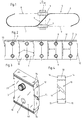
- the Structure 1 from several components 10, these components being shown in FIGS. 3 and 4 can.
- the transverse force rods 4 are here with their obliquely extending central section 5 in one a lateral edge of a component 10 formed groove 11 is used, the open Area of the groove 11 is closed accordingly by moving the next component 10. A shear force rod inserted in this way is thereby held captive.
- Cantilever panels and / or joint elements can also be designed as one-piece elements or from upper and lower parts, which are placed on top of each other in the vertical direction, consist.
- the present invention is essentially about the special training of Tubular body 3, which serve to accommodate tension and / or compression reinforcement elements. How already carried out, are in the building 1 or those forming such a building 1 Components 10 passage receptacles 2 are provided, in which the tubular body 3 can be used.
- the Tubular body 3 has several, at least approximately in, on its outer surface 45 Ribs 17 extending circumferentially, via which the tubular body 3 is force and / or can be positively supported on the inner wall 46 of the passage receptacle 2 in the building 1.
- a corresponding fit ensures a corresponding friction of the tubular body used achieved in the passage receptacle 2, so that a corresponding adhesion is given.
- the outer dimensions B of the ribs 17 slightly larger than the dimensions C of the passage receptacles 2.
- the differences in dimensions are chosen so that nevertheless a correspondingly simple insertion of the tubular body in the passage receptacle is possible without the risk of breaking out of the building structure 1 which would generally be made of foam.
- a plurality of ribs 17 running parallel to one another at a distance are on the External surface 45 of the tubular body 3 is provided. It is therefore a multiple support the inner wall 46 of the passage receptacle 2 possible, so that it never becomes one Tilting movement of the tubular body 3 used can come, even if a one-sided load would be present.
- the length X of the tubular body 3 greater than the thickness D of the structure 1, so that the tubular body 3 with its two ends over the front 40 of the structure 1 can protrude.
- the tubular body only protrudes on one side, but it is for reasons of strength and both ends same load options make sense to let the tubular body 3 protrude with both ends.
- a special rib compared to the other ribs 17 of larger diameter E to form a stop flange 18th intended. This is always a constant depth of penetration of the tubular body 3 in the Through hole 2 possible.
- the stop flange 18 always abuts the front 40 of the Building 1.
- tubular body 3 there can be one or more radially from the inside 48 to the outside guided bore (s) 20 are provided, these bores 20 usefully between in each case two ribs 17 open outwards and preferably in the installed position of the tubular body 3 in vertically upwards.
- these bores 20 usefully between in each case two ribs 17 open outwards and preferably in the installed position of the tubular body 3 in vertically upwards.
- tubular body according to the invention is advantageously made of plastic, however other materials can also be used. It would also be conceivable for such tubular bodies 3 made of metal, e.g. Aluminum or stainless steel.
- ribs is still too note that such ribs in the same way by a plurality of successive grooves can be formed.
- the basic principle is that the Outer surface of the tubular body several, at least approximately extending in the circumferential direction Ribs are present, through which the tubular body is non-positively and / or positively on the Can support the inner wall of the passage receptacle. Only through these measures are one Optimal and simple manufacture, simple assembly and a secure hold of the tubular body guaranteed.
Landscapes
- Engineering & Computer Science (AREA)
- Architecture (AREA)
- Physics & Mathematics (AREA)
- Electromagnetism (AREA)
- Civil Engineering (AREA)
- Structural Engineering (AREA)
- Joining Of Building Structures In Genera (AREA)
- Building Environments (AREA)
Claims (7)
- Elément de dalle en console et/ou élément de joint pour constructions en béton armé, comprenant un corps en une ou plusieurs parties, conçu pour recevoir des éléments d'armature opérant en traction et/ou en compression et le cas échéant des barres transversales, cette réception étant assurée par des ouvertures de passage, disposées à peu près transversalement à un plan vertical de symétrie et constituées par des éléments tubulaires insérés ou pouvant être insérés dans le corps, un logement de passage (2) réalisé préalablement dans le corps (1) étant prévu pour l'insertion de chaque élément tubulaire (3),
caractérisé en ce que
sur sa surface externe (45), chaque élément tubulaire (3) porte plusieurs nervures (17) transversales et en forme de cercles, disposées périphériquement, par l'intermédiaire desquelles l'élément tubulaire (3) peut s'appuyer à force et/ou par combinaison de formes sur la paroi interne (46) du logement de passage (2) prévu dans le corps. - Elément de dalle en console et/ou élément de jointoiement selon la revendication 1,
caractérisé en ce que
les dimensions externes (B) des nervures (17) sont un peu supérieures aux dimensions (C) du logement de passage (2) dans le cops (1), de sorte que l'élément tubulaire (3) peut être monté avec serrage dans un logement de passage (2). - Elément selon la revendication 1 ou 2,
caractérisé en ce que
sur la surface externe (45) de l'élément tubulaire (3) se trouvent plusieurs nervures (17) parallèles et espacées entre elles. - Elément selon la revendication 1,
caractérisé en ce que
l'élément tubulaire (3) a une longueur (X) supérieure à l'épaisseur (D) du corps (1), et porte sur sa surface externe (45) vers ses extrémités faisant saillie des deux côtés par rapport aux faces frontales (40) du corps (1), une ou plusieurs nervures (19). - Elément selon la revendication 1,
caractérisé en ce qu'
à une extrémité, ou à une certaine distance d'une extrémité de l'élément tubulaire (3), il est prévu une nervure ayant un diamètre (E) supérieur à celui des autres nervures, de manière à former une bride d'appui (18). - Elément selon la revendication 1,
caractérisé en ce que
dans l'élément tubulaire (3), il est prévu un ou plusieurs perçages (20) dirigés radialement de la face interne (48) vers l'extérieur. - Elément selon la revendication 6,
caractérisé en ce que
les perçages (20) débouchent tous vers l'extérieur entre deux nervures (17) et sont de préférence dirigés verticalement vers le haut, lorsque l'élément tubulaire (3) est monté.
Applications Claiming Priority (2)
| Application Number | Priority Date | Filing Date | Title |
|---|---|---|---|
| DE19519613 | 1995-05-29 | ||
| DE19519613A DE19519613C2 (de) | 1995-05-29 | 1995-05-29 | Kragplatten- und/oder Fugenelement für bewehrte Baukonstruktionen |
Publications (2)
| Publication Number | Publication Date |
|---|---|
| EP0745734A1 EP0745734A1 (fr) | 1996-12-04 |
| EP0745734B1 true EP0745734B1 (fr) | 2000-04-26 |
Family
ID=7763106
Family Applications (1)
| Application Number | Title | Priority Date | Filing Date |
|---|---|---|---|
| EP96108404A Expired - Lifetime EP0745734B1 (fr) | 1995-05-29 | 1996-05-28 | Elément de dalle en porte-à-faux et/ou élément de joint pour ouvrages de construction armés |
Country Status (3)
| Country | Link |
|---|---|
| EP (1) | EP0745734B1 (fr) |
| AT (1) | ATE192204T1 (fr) |
| DE (2) | DE19519613C2 (fr) |
Families Citing this family (6)
| Publication number | Priority date | Publication date | Assignee | Title |
|---|---|---|---|---|
| DE19705698B4 (de) * | 1997-02-14 | 2007-08-09 | Döllen, Heinz von | Vorgefertigtes, zwischen eine tragende Gebäudedecke und eine Balkonplattform im Zuge der Betonierung der Gebäudedecke und der Balkonplattform einzubetonierendes Dämmelement |
| DE19722051A1 (de) * | 1997-05-27 | 1998-12-03 | Schoeck Bauteile Gmbh | Modulares Bauelementsystem zur Wärmedämmung |
| DE19823100C1 (de) | 1998-05-22 | 2000-01-13 | Sfs Handels Holding Ag Heerbru | Kragplatten- und/oder Fugenelement für bewehrte Baukonstruktionen |
| WO2003054313A1 (fr) * | 2001-12-20 | 2003-07-03 | Sfs Locher Ag | Element de connexion de dalles en console et ensemble de connexion de dalles en console comprenant de tels elements de connexion de dalles en console |
| IT1402957B1 (it) * | 2010-12-10 | 2013-09-27 | Esse Solai Srl | Complesso di collegamento di strutture edili e procedimento per la sua realizzazione |
| FR3145763B1 (fr) * | 2023-02-10 | 2025-01-17 | Cohb Ind | Dispositif destiné à être associé à au moins un rupteur de pont thermique comprenant une languette latérale, et assemblage d’un tel dispositif avec au moins un rupteur de pont thermique. |
Family Cites Families (7)
| Publication number | Priority date | Publication date | Assignee | Title |
|---|---|---|---|---|
| CH665505A5 (de) * | 1984-03-22 | 1988-05-13 | Sprecher Energie Ag | Elektrische schaltanlage mit elektromechanisch verriegelbarer erdung in einer zelle. |
| DE3422905A1 (de) * | 1984-06-20 | 1986-01-02 | Hansjörg Dipl.-Ing. 7542 Schömberg Braun | Vorrichtung zum verbinden einer balkonplatte und einer geschossdecke |
| CH674752A5 (fr) * | 1988-03-18 | 1990-07-13 | Proceq Sa | |
| CH678076A5 (en) * | 1988-10-27 | 1991-07-31 | Erico Products S A | Insulating collar for reinforced concrete joints - has steel sleeves welded to one side with plastic collars on the other |
| DE8905521U1 (de) * | 1989-05-02 | 1989-06-29 | Hoff, Walter, 4000 Düsseldorf | Dämmendes Übergangselement, insbesondere für Kragplatten-Anschlüsse |
| CH681031A5 (fr) * | 1990-02-12 | 1992-12-31 | Stadler Heerbrugg Holding Ag | |
| DE4214704A1 (de) * | 1992-05-02 | 1993-11-04 | Schoeck Bauteile Gmbh | Bauelement zur waermedaemmung bei gebaeuden |
-
1995
- 1995-05-29 DE DE19519613A patent/DE19519613C2/de not_active Expired - Fee Related
-
1996
- 1996-05-28 DE DE59605023T patent/DE59605023D1/de not_active Expired - Fee Related
- 1996-05-28 AT AT96108404T patent/ATE192204T1/de not_active IP Right Cessation
- 1996-05-28 EP EP96108404A patent/EP0745734B1/fr not_active Expired - Lifetime
Also Published As
| Publication number | Publication date |
|---|---|
| EP0745734A1 (fr) | 1996-12-04 |
| DE19519613C2 (de) | 2000-04-13 |
| ATE192204T1 (de) | 2000-05-15 |
| DE59605023D1 (de) | 2000-05-31 |
| DE19519613A1 (de) | 1996-12-05 |
Similar Documents
| Publication | Publication Date | Title |
|---|---|---|
| CH676615A5 (fr) | ||
| EP4036338B1 (fr) | Dispositif de raccordement ultérieur à isolation thermique et à transfert de force d'une seconde partie d'ouvrage supportant la charge à une première partie d'ouvrage supportant la charge et ouvrage doté d'un tel dispositif | |
| EP1612339B1 (fr) | Elément isolant thermique pour la construction | |
| DE3700295C2 (de) | Bauelement zur Isolierung bei Gebäuden | |
| WO2008092664A2 (fr) | Élément de construction | |
| EP0745734B1 (fr) | Elément de dalle en porte-à-faux et/ou élément de joint pour ouvrages de construction armés | |
| EP0831183B1 (fr) | Elément de construction pour isolation thermique | |
| DE102008033585B4 (de) | Schubdornverbindung | |
| EP0959188B1 (fr) | Element de plaque et/ou de joint en porte-à-faux pour constructions en béton armé | |
| EP4067593A1 (fr) | Dispositif de liaison ultérieure à isolation thermique et à transfert de force d'une seconde partie d'ouvrage supportant la charge à une première partie d'ouvrage supportant la charge et ouvrage doté d'un tel dispositif | |
| EP0133875B1 (fr) | Elément de construction isolant thermique pour bâtiments | |
| DE102011115772A1 (de) | Gerüstanker mit Gerüstabstützung für Wärmedämmverbundsysteme | |
| EP0745732B1 (fr) | Elément pour dalle en console empêchant un pont thermique | |
| DE19814452A1 (de) | Anschluß zwischen einem tragenden und einem frei auskragenden Bauteil | |
| EP0745733A1 (fr) | Elément de dalle en porte-à-faux et/ou élément de joint pour ouvrages de construction armés | |
| DE19718021B4 (de) | Thermisch isolierendes Bauelement | |
| EP0697047A1 (fr) | Dispositif pour l'ancrage de montants de barrieres de securite dans un sol | |
| EP2607560A2 (fr) | Elément de raccordement de dalle | |
| EP3260615B1 (fr) | Élément de raccord pour éléments structuraux d'introduction de charge | |
| DE102011056105B4 (de) | Montagezusatzelement für die Befestigung von Bauelementen, z.B. Kellerlichtschächten an Gebäudewänden | |
| DE3444801A1 (de) | Aus einem ankersteg und einem ankerdorn bestehender anker zum anbringen von wandbekleidungsplatten an bauwerkswaenden | |
| DE19848055C2 (de) | Zuganker | |
| DE29505093U1 (de) | Beton-Fertigteil-Balkon | |
| EP2369073B1 (fr) | Élément de pose de dalles en console | |
| CH689231A5 (de) | Waermedaemmendes Kragplattenanschlusselement. |
Legal Events
| Date | Code | Title | Description |
|---|---|---|---|
| PUAI | Public reference made under article 153(3) epc to a published international application that has entered the european phase |
Free format text: ORIGINAL CODE: 0009012 |
|
| AK | Designated contracting states |
Kind code of ref document: A1 Designated state(s): AT CH DE FI FR LI |
|
| 17P | Request for examination filed |
Effective date: 19970604 |
|
| 17Q | First examination report despatched |
Effective date: 19970707 |
|
| GRAG | Despatch of communication of intention to grant |
Free format text: ORIGINAL CODE: EPIDOS AGRA |
|
| GRAG | Despatch of communication of intention to grant |
Free format text: ORIGINAL CODE: EPIDOS AGRA |
|
| GRAH | Despatch of communication of intention to grant a patent |
Free format text: ORIGINAL CODE: EPIDOS IGRA |
|
| GRAH | Despatch of communication of intention to grant a patent |
Free format text: ORIGINAL CODE: EPIDOS IGRA |
|
| GRAA | (expected) grant |
Free format text: ORIGINAL CODE: 0009210 |
|
| AK | Designated contracting states |
Kind code of ref document: B1 Designated state(s): AT CH DE FI FR LI |
|
| PG25 | Lapsed in a contracting state [announced via postgrant information from national office to epo] |
Ref country code: FR Free format text: LAPSE BECAUSE OF FAILURE TO SUBMIT A TRANSLATION OF THE DESCRIPTION OR TO PAY THE FEE WITHIN THE PRESCRIBED TIME-LIMIT Effective date: 20000426 Ref country code: FI Free format text: LAPSE BECAUSE OF FAILURE TO SUBMIT A TRANSLATION OF THE DESCRIPTION OR TO PAY THE FEE WITHIN THE PRESCRIBED TIME-LIMIT Effective date: 20000426 |
|
| REF | Corresponds to: |
Ref document number: 192204 Country of ref document: AT Date of ref document: 20000515 Kind code of ref document: T |
|
| REG | Reference to a national code |
Ref country code: CH Ref legal event code: EP |
|
| PG25 | Lapsed in a contracting state [announced via postgrant information from national office to epo] |
Ref country code: AT Free format text: LAPSE BECAUSE OF NON-PAYMENT OF DUE FEES Effective date: 20000528 |
|
| PG25 | Lapsed in a contracting state [announced via postgrant information from national office to epo] |
Ref country code: LI Free format text: LAPSE BECAUSE OF NON-PAYMENT OF DUE FEES Effective date: 20000531 Ref country code: CH Free format text: LAPSE BECAUSE OF NON-PAYMENT OF DUE FEES Effective date: 20000531 |
|
| REF | Corresponds to: |
Ref document number: 59605023 Country of ref document: DE Date of ref document: 20000531 |
|
| EN | Fr: translation not filed | ||
| REG | Reference to a national code |
Ref country code: CH Ref legal event code: PL |
|
| PLBE | No opposition filed within time limit |
Free format text: ORIGINAL CODE: 0009261 |
|
| STAA | Information on the status of an ep patent application or granted ep patent |
Free format text: STATUS: NO OPPOSITION FILED WITHIN TIME LIMIT |
|
| PG25 | Lapsed in a contracting state [announced via postgrant information from national office to epo] |
Ref country code: DE Free format text: LAPSE BECAUSE OF NON-PAYMENT OF DUE FEES Effective date: 20010301 |
|
| 26N | No opposition filed |