EP4067593A1 - Dispositif de liaison ultérieure à isolation thermique et à transfert de force d'une seconde partie d'ouvrage supportant la charge à une première partie d'ouvrage supportant la charge et ouvrage doté d'un tel dispositif - Google Patents
Dispositif de liaison ultérieure à isolation thermique et à transfert de force d'une seconde partie d'ouvrage supportant la charge à une première partie d'ouvrage supportant la charge et ouvrage doté d'un tel dispositif Download PDFInfo
- Publication number
- EP4067593A1 EP4067593A1 EP22163162.5A EP22163162A EP4067593A1 EP 4067593 A1 EP4067593 A1 EP 4067593A1 EP 22163162 A EP22163162 A EP 22163162A EP 4067593 A1 EP4067593 A1 EP 4067593A1
- Authority
- EP
- European Patent Office
- Prior art keywords
- storage box
- tension rods
- longitudinal side
- load
- structural part
- Prior art date
- Legal status (The legal status is an assumption and is not a legal conclusion. Google has not performed a legal analysis and makes no representation as to the accuracy of the status listed.)
- Granted
Links
Images


Classifications
-
- E—FIXED CONSTRUCTIONS
- E04—BUILDING
- E04B—GENERAL BUILDING CONSTRUCTIONS; WALLS, e.g. PARTITIONS; ROOFS; FLOORS; CEILINGS; INSULATION OR OTHER PROTECTION OF BUILDINGS
- E04B1/00—Constructions in general; Structures which are not restricted either to walls, e.g. partitions, or floors or ceilings or roofs
- E04B1/003—Balconies; Decks
- E04B1/0038—Anchoring devices specially adapted therefor with means for preventing cold bridging
-
- E—FIXED CONSTRUCTIONS
- E04—BUILDING
- E04B—GENERAL BUILDING CONSTRUCTIONS; WALLS, e.g. PARTITIONS; ROOFS; FLOORS; CEILINGS; INSULATION OR OTHER PROTECTION OF BUILDINGS
- E04B1/00—Constructions in general; Structures which are not restricted either to walls, e.g. partitions, or floors or ceilings or roofs
- E04B1/62—Insulation or other protection; Elements or use of specified material therefor
- E04B1/74—Heat, sound or noise insulation, absorption, or reflection; Other building methods affording favourable thermal or acoustical conditions, e.g. accumulating of heat within walls
- E04B1/76—Heat, sound or noise insulation, absorption, or reflection; Other building methods affording favourable thermal or acoustical conditions, e.g. accumulating of heat within walls specifically with respect to heat only
- E04B1/78—Heat insulating elements
-
- E—FIXED CONSTRUCTIONS
- E04—BUILDING
- E04B—GENERAL BUILDING CONSTRUCTIONS; WALLS, e.g. PARTITIONS; ROOFS; FLOORS; CEILINGS; INSULATION OR OTHER PROTECTION OF BUILDINGS
- E04B5/00—Floors; Floor construction with regard to insulation; Connections specially adapted therefor
- E04B5/16—Load-carrying floor structures wholly or partly cast or similarly formed in situ
-
- E—FIXED CONSTRUCTIONS
- E04—BUILDING
- E04B—GENERAL BUILDING CONSTRUCTIONS; WALLS, e.g. PARTITIONS; ROOFS; FLOORS; CEILINGS; INSULATION OR OTHER PROTECTION OF BUILDINGS
- E04B1/00—Constructions in general; Structures which are not restricted either to walls, e.g. partitions, or floors or ceilings or roofs
- E04B1/62—Insulation or other protection; Elements or use of specified material therefor
- E04B1/74—Heat, sound or noise insulation, absorption, or reflection; Other building methods affording favourable thermal or acoustical conditions, e.g. accumulating of heat within walls
- E04B1/76—Heat, sound or noise insulation, absorption, or reflection; Other building methods affording favourable thermal or acoustical conditions, e.g. accumulating of heat within walls specifically with respect to heat only
- E04B2001/7679—Means preventing cold bridging at the junction of an exterior wall with an interior wall or a floor
Definitions
- the invention relates to a device for the subsequent thermally insulating, force-transmitting connection of a second load-bearing structure part to a first load-bearing structure part, in particular a building ceiling to a balcony slab, and a structure with such a device.
- a device for the subsequent connection of a prefabricated balcony to a building emerges.
- a recess is provided on the upper side of the balcony, in which the tension rods are connected to one another.
- the present invention is based on the object of creating a device for the subsequent thermally insulating, force-transmitting connection of a second load-bearing structure part to a first load-bearing structure part, which has an advantageous structure.
- a further object of the present invention consists in specifying a building with such a device.
- first tension rods protrude into the storage box on the first longitudinal side of the storage box
- second tension rods protrude into the storage box on the second longitudinal side
- the connecting device is arranged in the storage box. Due to the fact that the connecting device is arranged in the storage box, the connecting device can be easily protected from environmental influences by closing the storage box. At the same time, an attractive visual appearance is obtained since the connecting device is not visible from the outside after the storage box has been closed. A later filling of the area of the connecting device, for example with quick-hardening mortar or the like, can be omitted. This simplifies assembly on site.
- the arrangement of a recess in the first or the second part of the structure, in which the connecting device is arranged can be dispensed with. This avoids impairing the appearance of the first or second part of the structure.
- the tension rods protruding into the storage box on the first long side are advantageously provided for embedding in the first part of the building and the tension rods protruding into the storage box on the second long side are advantageously provided for embedding in the second part of the building.
- connection device Due to the arrangement of the connection device in the storage box, sufficient corrosion protection of the connection device and of the sections of the tension rods protruding into the storage box can be ensured in a simple manner. A supplementary corrosion protection can be omitted.
- the tension rods are intended to introduce forces into the concrete of the structural parts.
- the length of the tension rods required for this is calculated based on the forces to be transmitted. For the calculation of the length of the tie rods, only those sections of the tie rods that are well embedded in concrete of sufficient strength can be fully considered. If recesses are subsequently filled with sealing compound, the strength of the sealing compound and its connection to the tension rods can often not be guaranteed to a sufficient extent, so that tension rod sections running in the recesses cannot be included in the calculation or not to the same extent as tension rod sections that project into in-situ concrete or into concrete cast in the precast plant.
- the entire length of the tension rods lying outside of the storage box can be embedded in the first or second building part during the manufacture of the building parts and a recess does not have to be subsequently filled with sealing compound such as mortar the entire length of the tension rods running outside the storage box must be taken into account when calculating the required length of the tension rods, in particular when calculating the overlap length. As a result, a shorter length of the tension rods is required.
- the first tension rods and the second tension rods are advantageously arranged in a common plane running perpendicular to the vertical direction. As a result, a favorable introduction of force is achieved. At the same time, the connection of the tension rods in the storage box is possible in a simple manner, since no height offset between the tension rods has to be compensated.
- the connecting device particularly advantageously comprises a connecting plate which is arranged in the storage box and on which the first tension rods and the second tension rods are fixed.
- the connection plate is on a Arranged longitudinal side of the storage box in the storage box.
- the connecting plate is particularly advantageously arranged on the longitudinal side of the storage box that is closer to the balcony plate.
- the tie rods embedded in the building and protruding through the long side of the storage box remote from the balcony slab are preferably firmly connected to the connecting slab, for example by means of welded joints.
- the tension rods of the balcony slab are preferably pushed through openings in the connecting slab and fixed using screw connections, preferably using nuts.
- the connecting device advantageously includes at least one screw connection.
- the openings of the connecting plate are advantageously dimensioned so large that a tolerance compensation between the tie rods of the building and the tie rods of the balcony slab is possible.
- the storage box has at least one closable access opening, via which the connecting device is accessible.
- the access opening is particularly preferably designed to be resealable, so that the connecting device is accessible again after assembly by opening the storage box again.
- the access opening extends over the entire length and the entire width of the storage box. However, it can also be provided that the access opening only extends over the area of the storage box that covers the connecting device. In an alternative design, the access opening may only extend over the area of the threaded connections. Provision can also be made for the storage box to have a plurality of access openings, via which one or more threaded connections are accessible in each case.
- the storage box is preferably filled with mineral wool as insulating material.
- the insulating material is advantageously at least partially introduced after the first and second tension rods have been connected to one another in the storage box.
- a simple one Design results when the storage box is made of plastic.
- the storage box is particularly preferably made from extruded profiles. This enables the storage box to be produced simply and economically.
- the storage box preferably has a base body and at least one cover that can be connected to the base body.
- the cover is preferably detachably connected to the base body.
- the cover can be connected to the base body, for example, via a snap connection, latching or clamping.
- a different type of connection between the cover and the base body can also be advantageous.
- provision can be made for the cover to be permanently connected to the base body, for example by means of an adhesive connection.
- the storage box can be open at its end faces perpendicular to the longitudinal direction. This is particularly advantageous when several storage boxes are arranged next to one another on the front side. In particular for storage boxes that close the insulating joint in the longitudinal direction, it is advantageously provided that the storage box is closed on at least one end face. A further cover can be provided for this purpose.
- the storage box is advantageously designed to be closed in the transverse direction and in the vertical direction.
- At least one support for the vertical support of the second part of the structure is advantageously arranged on the second longitudinal side of the storage box.
- At least one transverse force bar advantageously protrudes through the storage box.
- the at least one transverse force bar is fixed to the support for the vertical support of the second part of the structure.
- a different connection of the shear force bar can also be advantageous.
- the structure has a first load-bearing structure part made of concrete and a second load-bearing structure part made of concrete as well as a device for connecting the second load-bearing structure part to the first load-bearing structure part.
- the device advantageously has two units that can be connected to one another, namely a unit to be fixed to the first building part and a unit to be fixed to the second building part, which can be connected to one another after the building parts have been produced.
- First tension rods are preferably embedded in the first structural part and second tension rods in the second structural part.
- the insulating body is preferably fixed to the first part of the structure. By connecting the tension rods to one another, the second part of the structure can be fixed to the first part of the structure.
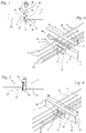
- the building 50 has a first building part 2, in the exemplary embodiment a building ceiling, and a second building part 3, in the exemplary embodiment a balcony slab.
- the second structural part 3 is connected to the first structural part 2 via a thermally insulating component 1 in a thermally insulating and force-transmitting manner.
- the load-bearing parts of the structure 2 and 3 are made of concrete, in the exemplary embodiment made of steel-reinforced concrete.
- the load-bearing structural part 3 has been fixed to the first load-bearing structural part 2 after it has been produced.
- the load-bearing structural part 3 can be produced with high quality, for example in the prefabricated parts factory, and can be fixed very quickly to the structural part 2 on the construction site, which shortens crane times and thereby reduces production costs.
- the second building part 3 can, for example, be a balcony manufactured as a finished part.
- the thermally insulating component 1 comprises an insulating body 5 which is arranged in a parting line 4 between the first structural part 2 and the second structural part 3 .
- the insulator 5 has a first longitudinal side 6 on the first Building part 2 is arranged.
- the second, opposite longitudinal side 7 runs adjacent to the second structural part 3.
- a narrow gap is formed between the insulating body 5 and the second structural part 3.
- the second structural part 3 bears against the insulating body 5 .
- the insulating body 5 has a storage box 33 which is filled with insulating material 32 .
- the storage box 33 is advantageously made of plastic.
- the storage box 33 is made in particular from one or more extruded plastic profiles.
- the insulating material 32 is preferably mineral wool. However, another insulating material can also be provided.
- the storage box 33 is advantageously closed on its longitudinal sides 6 and 7 .
- one or more storage boxes 33 extend over the entire length of the expansion joint 4.
- Adjacent storage boxes 33 are advantageously arranged in such a way that their end faces 34 adjoin one another or—if the parting line 4 is angled—that an end face 34 of a storage box 33 adjoins a longitudinal side 6 of an adjacent storage box 33 is adjacent.
- the end faces 34 of the storage box 33 are also in the Figures 7 and 8 shown.
- the storage box 33 has a longitudinal direction 28 which is aligned in the longitudinal direction of the expansion joint 4 .
- the longitudinal direction 28 preferably runs horizontally in the installed state.
- the end faces 34 run transversely, in particular perpendicularly, to the longitudinal direction 28.
- the storage box 33 has a vertical direction 30, such as 1 shows, which runs perpendicular to the longitudinal direction 28.
- the vertical direction 30 preferably runs vertically in the installed state.
- the storage box 33 has a 1 shown transverse direction 29, which runs from the first longitudinal side 6 to the opposite longitudinal side 7.
- the transverse direction 29 is aligned perpendicularly to the longitudinal direction 28 and perpendicularly to the vertical direction 30 .
- the transverse direction 29 preferably runs horizontally in the installed state.
- the storage box 33 has an underside 8 oriented in the longitudinal direction 28 and connecting the long sides 6 and 7 and an upper side 47 oriented in the longitudinal direction 28 and connecting the long sides 6 and 7 .
- the top 47 is arranged above the bottom 8 in the installed state.
- the storage box 33 is advantageously closed on the upper side 47 and the lower side 8 .
- the storage box 33 can be designed to be open or closed on the end faces 34 running transversely to the longitudinal direction 28 .
- the thermally insulating component 1 together with other elements, forms a device for the force-transmitting connection of the second building part 3 to the first building part 2.
- the device consists of the thermally insulating component 1, which is fixed to the first building part 2, and other means arranged on the second building part 3 for power transmission.
- the force transmission means arranged on the second structure part 3 are advantageously detachably connected to the force transmission means arranged in the first structure part 2 . As a result, subsequent connection of the second structural part 3 to the first structural part 2 is possible.
- the device For the transmission of tensile forces between the structural parts 2 and 3, the device comprises first tension rods 9, which are embedded in the first structural part 2, and second tension rods 10, which are embedded in the second structural part 3.
- the tension rods 9 and 10 are connected to one another in a force-transmitting manner via a connecting device 35 .
- the connecting device 35 is arranged in the storage box 33 .
- the first tension rods 9 protrude through the first longitudinal side 6 into the storage box 33.
- the second tension rods 10 protrude through the second longitudinal side 7 into the storage box 33.
- the connecting device 35 comprises a connecting plate 11.
- the first tension rods 9 are firmly connected to the connecting plate 11, in the exemplary embodiment via welded connections 15 ( 2 ).
- the connecting plate 11 is in the storage box 33 on the inside of the second longitudinal side 7 arranged. This results in a space-saving arrangement and screw connections 40 of the second tension rods 10 are easily accessible.
- the second tension rods 10 are screwed to the connecting plate 11 .
- the connection plate 11 has openings 36 ( 1 ) through which the second tension rods 10 protrude into the interior of the storage box 33 .
- the second tension rods 10 have threaded sections 41 at their ends protruding into the storage box 33.
- the threaded sections 41 form screw connections 40 with fastening nuts 14 screwed onto the threaded sections 41.
- the second tension rods 10 are connected to the connecting plate 11 via the screw connections 40.
- a fastening nut 14 is screwed onto a threaded section 41 of each tension rod 10 on the side of the connecting plate 11 which is arranged away from the second longitudinal side 7 .
- a disk 21 is arranged between the fastening nuts 14 and the connecting plate 11 .
- the first tie rods 9 and the second tie rods 10 protrude from the connecting plate 11 on opposite sides.
- the tension rods 9 and 10 end in the interior of the storage box 33.
- both the first tension rods 9 and the second tension rods 10 are connected to the connecting plate 11 via screw connections 40 .
- Another force-transmitting connection of the tension rods 9 and 10 can also be advantageous.
- the connecting device 35 is designed in such a way that the tension rods 9 and 10 can be connected to one another after the building parts 2 and 3 have been produced.
- a support 17 is arranged on the second structural part 2 for the transmission of pressure forces and transverse forces.
- the support 17 is designed as a support bracket in the exemplary embodiment.
- the support 17 advantageously forms part of the thermally insulating component 1 and is in particular held captive on the storage box 33 .
- the support 17 is firmly connected to transverse force bars 16 .
- the transverse force bars 16 are in embedded in the concrete of the first structural part 2 and thereby connected to the first structural part 2 in a force-transmitting manner.
- the support 17 is supported in the horizontal direction on at least one first pressure rod 19 embedded in the first structural part 2 .
- the first pressure rod 19 extends from the second longitudinal side 7 through the first longitudinal side 6 of the storage box 33 into the first structural part 2.
- the first pressure rod 19 forms a pressure element.
- a different design of the pressure element can also be advantageous. It can be provided that the support 17 is firmly connected to the at least one compression bar 19 .
- a support bracket 31 is embedded in the second structural part 3 and rests on the support 17 . Pressure forces acting in the horizontal direction as well as transverse forces acting in the vertical direction are introduced into the support 17 from the second structural part 3 via the support angle 31 .
- the support bracket 31 is connected to at least one second pressure rod 20 .
- the at least one second pressure rod 20 is embedded in the second structural part 3 . A different type of pressure force introduction into the second part of the structure can also be advantageous.
- the first tension rods 9 have longitudinal axes 12 and the second tension rods 10 have longitudinal axes 13, as in FIG 2 is shown.
- the longitudinal axes 12 and 13 lie in a common, horizontal plane 38.
- the plane 38 runs parallel to the longitudinal direction 28 and parallel to the transverse direction 29.
- the plane 38 runs perpendicular to the vertical direction 30.
- the tension rods 9 and 10 are offset from one another in the plane 38 arranged.
- the longitudinal axes 12 and 13 of adjacent tension rods 9 and 10 in the exemplary embodiment have an offset a relative to one another, measured in the longitudinal direction 28 .
- the underside 8 of the storage box 33 runs approximately in one plane with an underside 45 of the support 17 and an underside 46 of the second structural part 3.
- the Figures 3 to 6 show the design of the storage box 33 in detail.
- the storage box 33 is formed by a base body 42 and a cover 43 .
- the cover 43 is shown removed.
- the cover 43 can be placed on the base body 42 in the direction of the arrow 48 and connected to it.
- an access opening 44 is open.
- the connecting device 35 is accessible from outside the storage box 33 via the access opening 44 .
- the second tension rods 10 can be pushed through openings in the connecting plate 11 and then fixed using the fastening nuts 14 .
- the fastening nuts 14 are accessible through the access opening 44 from the outside.
- the base body 42 can be filled with insulating material, preferably with mineral wool, and the cover 43 can then be put on and fixed.
- the cover 43 can be fixed to the base body 42 in particular via a detachable connection, for example via a snap connection, a clamp connection or a latching connection.
- the detachable connection is advantageously designed in such a way that the cover 43 can be removed again without being destroyed.
- a different connection of cover 43 and base body 42 can also be provided, for example an adhesive connection.
- a formwork body 37 is arranged on the second long side 7 of the storage box 33 and is embedded in the second structural part 3 .
- the formwork body 37 forms recesses for cheeks 18 of the support 17 ( 7 ).
- the support bracket 31 rests on the formwork body 37, such as 3 indicates.
- two second pressure rods 20 are fixed to the support bracket 31 in the embodiment. A different number of second pressure rods 20 can also be provided.
- the access opening 33 extends over the entire width b measured in the transverse direction 29 and the entire length c measured in the longitudinal direction 28 of the storage box 32.
- the storage box 33 at its perpendicular to the longitudinal direction 28 end faces 34 open.
- the storage box 33 is designed to be completely closed in the closed state.
- the base body 42 is U-shaped in the exemplary embodiment and forms the underside 8 and the longitudinal sides 6 and 7 of the storage box 33.
- the cover 42 is also U-shaped in cross section, the legs of the U forming the cover 42 being short.
- the Figures 7 to 10 show the thermally insulating component 1 on the first structural part 2 in detail.
- the first tension rods 9 are only shown schematically and without the connecting device 35 .
- the connection plate 11 at which the tension rods 9 end in the storage box 33 is not shown.
- the support 17 of the thermally insulating component 1 has two legs 24 and 25 which are aligned at right angles to one another in the exemplary embodiment.
- the legs 24 and 25 run parallel to the longitudinal direction 28 of the storage box 33.
- the first leg 24 runs parallel to the vertical direction 30.
- the first leg 24 is advantageously aligned vertically when installed on the building 50.
- the second leg 25 runs parallel to the transverse direction 29 and is advantageously aligned horizontally in the installed state.
- a bearing surface 23 for the transmission of transverse forces is formed on the side pointing upwards in the installed state.
- the second leg 25 of the support 17 runs close to the underside 8 of the insulating body 5.
- the second structural part 3 can be placed on the supporting surface 23 and then fixed to the first structural part 2 via the screw connections 40.
- the space spanned by the two legs 24 and 25 is closed at the ends of the support 17 by cheeks 18 running transversely to the longitudinal direction 28 .
- the shear force rods 16 are embedded in the first structural part 2 and have a section 26 running at an incline to the vertical direction 30 and at an incline to the transverse direction 29 .
- the inclined section 26 drops from the first structural part 2 to the second structural part 3 .
- the inclined sections 26 of the two transverse force bars 16 run on the opposite outer sides of the cheeks 18.
- Each inclined section 26 is fixed directly to a cheek 18, in the exemplary embodiment by welding.
- the inclined section 26 of the at least one transverse force bar 16 protrudes through the insulating body 5.
- the support 17 is arranged outside the storage box 33, namely on the longitudinal side 7 of the storage box 33 facing away from the first longitudinal side 6.
- the support 17 thus protrudes into the area of the second building part 3.
- the first pressure rods 19 are fixed to the first leg 24.
- the pressure rods 19 are designed as comparatively long, straight rods that are embedded in the concrete of the first part 2 of the structure for the transmission of compressive force.
- the struts 19 can be bolted to the support 17, welded or attached in some other way. A different configuration of the elements for transmitting the compressive force can also be advantageous.
- the support 17 is advantageously made of metal.
- the support 17 is formed, in particular including the at least one cheek 18, from sheet metal, preferably from at least two sheet metal parts connected to one another.
- both the tie rods 10 and the tie rods 9 are fixed to the connecting plate 11 via fastening nuts 14 .
- a washer 21 is advantageously arranged between each fastening nut 14 and the connecting plate 11 .
- the discs 21 can also be omitted.
Landscapes
- Engineering & Computer Science (AREA)
- Architecture (AREA)
- Physics & Mathematics (AREA)
- Electromagnetism (AREA)
- Civil Engineering (AREA)
- Structural Engineering (AREA)
- Acoustics & Sound (AREA)
- Building Environments (AREA)
- Conveying And Assembling Of Building Elements In Situ (AREA)
Applications Claiming Priority (1)
| Application Number | Priority Date | Filing Date | Title |
|---|---|---|---|
| DE202021101776.7U DE202021101776U1 (de) | 2021-04-01 | 2021-04-01 | Einrichtung zur nachträglichen thermisch isolierenden, kraftübertragenden Anbindung eines zweiten lastaufnehmenden Bauwerksteils an ein erstes lastaufnehmendes Bauwerksteil und Bauwerk mit einer solchen Einrichtung |
Publications (2)
| Publication Number | Publication Date |
|---|---|
| EP4067593A1 true EP4067593A1 (fr) | 2022-10-05 |
| EP4067593B1 EP4067593B1 (fr) | 2024-02-28 |
Family
ID=75784721
Family Applications (1)
| Application Number | Title | Priority Date | Filing Date |
|---|---|---|---|
| EP22163162.5A Active EP4067593B1 (fr) | 2021-04-01 | 2022-03-21 | Dispositif de liaison ultérieure à isolation thermique et à transfert de force d'une seconde partie d'ouvrage supportant la charge à une première partie d'ouvrage supportant la charge et ouvrage doté d'un tel dispositif |
Country Status (6)
| Country | Link |
|---|---|
| US (1) | US12559931B2 (fr) |
| EP (1) | EP4067593B1 (fr) |
| DE (1) | DE202021101776U1 (fr) |
| DK (1) | DK4067593T3 (fr) |
| FI (1) | FI4067593T3 (fr) |
| PL (1) | PL4067593T3 (fr) |
Families Citing this family (2)
| Publication number | Priority date | Publication date | Assignee | Title |
|---|---|---|---|---|
| DE202021000466U1 (de) * | 2021-02-01 | 2021-04-22 | Halfen Gmbh | Einrichtung zur nachträglichen thermisch isolierenden, kraftübertragenden Anbindung eines zweiten lastaufnehmenden Bauwerksteils an ein erstes lastaufnehmendes Bauwerksteil und Bauwerk mit einer solchen Einrichtung |
| DE202023103836U1 (de) * | 2023-07-10 | 2023-10-04 | Leviat Ag | Positioniervorrichtung |
Citations (4)
| Publication number | Priority date | Publication date | Assignee | Title |
|---|---|---|---|---|
| KR101462801B1 (ko) * | 2013-07-26 | 2014-11-21 | 청원화학 주식회사 | 불연속 철근 및 결합 부재를 이용한 열교차단 장치 |
| WO2017086777A1 (fr) | 2015-11-16 | 2017-05-26 | T&R Engineering B.V. | Bâtiment et balcon |
| GB2567685A (en) * | 2017-10-20 | 2019-04-24 | Insula Ltd | Thermally insulating anchor |
| EP3613910A1 (fr) * | 2018-08-22 | 2020-02-26 | iBALKON Dariusz Glaza | Connecteur de construction à isolation thermique |
Family Cites Families (5)
| Publication number | Priority date | Publication date | Assignee | Title |
|---|---|---|---|---|
| DE102006011336A1 (de) * | 2006-03-09 | 2007-09-13 | Schöck Bauteile GmbH | Bauelement zur Wärmedämmung |
| DK2653625T3 (en) * | 2012-04-20 | 2019-03-11 | Halfen Gmbh | Thermally insulating structural element |
| BE1023762B1 (nl) * | 2016-01-12 | 2017-07-14 | Plakabeton Nv | Constructie-element voor het realiseren van een verbinding tussen thermisch geisoleerde delen van een gebouw |
| GB201819196D0 (en) * | 2018-11-26 | 2019-01-09 | Ancon Ltd | Building element, system and method |
| DE202021000466U1 (de) * | 2021-02-01 | 2021-04-22 | Halfen Gmbh | Einrichtung zur nachträglichen thermisch isolierenden, kraftübertragenden Anbindung eines zweiten lastaufnehmenden Bauwerksteils an ein erstes lastaufnehmendes Bauwerksteil und Bauwerk mit einer solchen Einrichtung |
-
2021
- 2021-04-01 DE DE202021101776.7U patent/DE202021101776U1/de active Active
-
2022
- 2022-03-21 FI FIEP22163162.5T patent/FI4067593T3/fi active
- 2022-03-21 DK DK22163162.5T patent/DK4067593T3/da active
- 2022-03-21 EP EP22163162.5A patent/EP4067593B1/fr active Active
- 2022-03-21 PL PL22163162.5T patent/PL4067593T3/pl unknown
- 2022-03-31 US US17/709,456 patent/US12559931B2/en active Active
Patent Citations (4)
| Publication number | Priority date | Publication date | Assignee | Title |
|---|---|---|---|---|
| KR101462801B1 (ko) * | 2013-07-26 | 2014-11-21 | 청원화학 주식회사 | 불연속 철근 및 결합 부재를 이용한 열교차단 장치 |
| WO2017086777A1 (fr) | 2015-11-16 | 2017-05-26 | T&R Engineering B.V. | Bâtiment et balcon |
| GB2567685A (en) * | 2017-10-20 | 2019-04-24 | Insula Ltd | Thermally insulating anchor |
| EP3613910A1 (fr) * | 2018-08-22 | 2020-02-26 | iBALKON Dariusz Glaza | Connecteur de construction à isolation thermique |
Also Published As
| Publication number | Publication date |
|---|---|
| EP4067593B1 (fr) | 2024-02-28 |
| FI4067593T3 (fi) | 2024-03-28 |
| DE202021101776U1 (de) | 2021-04-19 |
| DK4067593T3 (da) | 2024-05-27 |
| US12559931B2 (en) | 2026-02-24 |
| US20220316201A1 (en) | 2022-10-06 |
| PL4067593T3 (pl) | 2024-06-10 |
Similar Documents
| Publication | Publication Date | Title |
|---|---|---|
| EP4036338B1 (fr) | Dispositif de raccordement ultérieur à isolation thermique et à transfert de force d'une seconde partie d'ouvrage supportant la charge à une première partie d'ouvrage supportant la charge et ouvrage doté d'un tel dispositif | |
| EP2653625B1 (fr) | Composant à isolation thermique | |
| EP4286618B1 (fr) | Dispositif de liaison ultérieure d'une deuxième partie de construction recevant une charge à une première partie de construction recevant une charge et construction dotée d'un tel dispositif | |
| EP0338972A1 (fr) | Elément de raccordement pour panneau en porte-à-faux | |
| DE1903129B2 (de) | Vorrichtung zum Anschließen eines Trägers an eine Betonstütze | |
| EP4067593B1 (fr) | Dispositif de liaison ultérieure à isolation thermique et à transfert de force d'une seconde partie d'ouvrage supportant la charge à une première partie d'ouvrage supportant la charge et ouvrage doté d'un tel dispositif | |
| DE19652165C2 (de) | Fertigbauteil für eine auskragende Balkonplatte | |
| DE69000343T2 (de) | Fassadenstruktur des vorhangfassadentyps mit gespannten kabeln oder draehten. | |
| DE1810434C3 (de) | Hochbauwerk | |
| DE10147831B4 (de) | Ständerwand | |
| DE3403537A1 (de) | Balkonfertig-bauelement fuer gebaeude | |
| EP1270833B1 (fr) | Elément de construction pour l'isolation thermique | |
| DE102019133999A1 (de) | Anordnung zum Verbinden eines Bauwerkteils mit einem dem Bauwerkteil vorgelagerten Außenteil | |
| EP0745734B1 (fr) | Elément de dalle en porte-à-faux et/ou élément de joint pour ouvrages de construction armés | |
| DE19928757C2 (de) | Montageträgersystem und Verfahren zur Montage eines Fertigbauteils an einem Gebäudeteil | |
| CH690966A5 (de) | Isolierendes Anschlusselement für Kragplatten. | |
| EP2607560B1 (fr) | Élément de raccordement de dalle | |
| EP0796961B1 (fr) | Bétoncellulaire avec système d'armatures | |
| DE102016118014A1 (de) | Binder, insbesondere Dachbinder für eine Halle | |
| EP0106297A2 (fr) | Elément de construction pour la fabrication de murs en béton et mur de bâtiment fabriqué avec celui-ci | |
| EP3835501B1 (fr) | Arrangement pour connecter une pièce de construction avec une partie extérieure frontale | |
| EP4050170B1 (fr) | Construction pourvue d'élément thermoisolant | |
| EP3839162A1 (fr) | Composant thermo-isolant destiné à être utilisé dans une fente de séparation entre deux parties de construction et construction | |
| DE9406442U1 (de) | Bauelement | |
| DE29505093U1 (de) | Beton-Fertigteil-Balkon |
Legal Events
| Date | Code | Title | Description |
|---|---|---|---|
| PUAI | Public reference made under article 153(3) epc to a published international application that has entered the european phase |
Free format text: ORIGINAL CODE: 0009012 |
|
| STAA | Information on the status of an ep patent application or granted ep patent |
Free format text: STATUS: THE APPLICATION HAS BEEN PUBLISHED |
|
| AK | Designated contracting states |
Kind code of ref document: A1 Designated state(s): AL AT BE BG CH CY CZ DE DK EE ES FI FR GB GR HR HU IE IS IT LI LT LU LV MC MK MT NL NO PL PT RO RS SE SI SK SM TR |
|
| STAA | Information on the status of an ep patent application or granted ep patent |
Free format text: STATUS: REQUEST FOR EXAMINATION WAS MADE |
|
| 17P | Request for examination filed |
Effective date: 20230323 |
|
| RBV | Designated contracting states (corrected) |
Designated state(s): AL AT BE BG CH CY CZ DE DK EE ES FI FR GB GR HR HU IE IS IT LI LT LU LV MC MK MT NL NO PL PT RO RS SE SI SK SM TR |
|
| GRAP | Despatch of communication of intention to grant a patent |
Free format text: ORIGINAL CODE: EPIDOSNIGR1 |
|
| STAA | Information on the status of an ep patent application or granted ep patent |
Free format text: STATUS: GRANT OF PATENT IS INTENDED |
|
| RIC1 | Information provided on ipc code assigned before grant |
Ipc: E04B 1/00 20060101AFI20231019BHEP |
|
| INTG | Intention to grant announced |
Effective date: 20231110 |
|
| P01 | Opt-out of the competence of the unified patent court (upc) registered |
Effective date: 20231204 |
|
| GRAS | Grant fee paid |
Free format text: ORIGINAL CODE: EPIDOSNIGR3 |
|
| GRAA | (expected) grant |
Free format text: ORIGINAL CODE: 0009210 |
|
| STAA | Information on the status of an ep patent application or granted ep patent |
Free format text: STATUS: THE PATENT HAS BEEN GRANTED |
|
| AK | Designated contracting states |
Kind code of ref document: B1 Designated state(s): AL AT BE BG CH CY CZ DE DK EE ES FI FR GB GR HR HU IE IS IT LI LT LU LV MC MK MT NL NO PL PT RO RS SE SI SK SM TR |
|
| REG | Reference to a national code |
Ref country code: GB Ref legal event code: FG4D Free format text: NOT ENGLISH |
|
| REG | Reference to a national code |
Ref country code: CH Ref legal event code: EP |
|
| REG | Reference to a national code |
Ref country code: DE Ref legal event code: R096 Ref document number: 502022000545 Country of ref document: DE |
|
| REG | Reference to a national code |
Ref country code: IE Ref legal event code: FG4D Free format text: LANGUAGE OF EP DOCUMENT: GERMAN |
|
| REG | Reference to a national code |
Ref country code: FI Ref legal event code: FGE |
|
| REG | Reference to a national code |
Ref country code: NL Ref legal event code: FP |
|
| REG | Reference to a national code |
Ref country code: SE Ref legal event code: TRGR |
|
| REG | Reference to a national code |
Ref country code: DK Ref legal event code: T3 Effective date: 20240523 |
|
| REG | Reference to a national code |
Ref country code: LT Ref legal event code: MG9D |
|
| PG25 | Lapsed in a contracting state [announced via postgrant information from national office to epo] |
Ref country code: IS Free format text: LAPSE BECAUSE OF FAILURE TO SUBMIT A TRANSLATION OF THE DESCRIPTION OR TO PAY THE FEE WITHIN THE PRESCRIBED TIME-LIMIT Effective date: 20240628 |
|
| PG25 | Lapsed in a contracting state [announced via postgrant information from national office to epo] |
Ref country code: LT Free format text: LAPSE BECAUSE OF FAILURE TO SUBMIT A TRANSLATION OF THE DESCRIPTION OR TO PAY THE FEE WITHIN THE PRESCRIBED TIME-LIMIT Effective date: 20240228 |
|
| PG25 | Lapsed in a contracting state [announced via postgrant information from national office to epo] |
Ref country code: GR Free format text: LAPSE BECAUSE OF FAILURE TO SUBMIT A TRANSLATION OF THE DESCRIPTION OR TO PAY THE FEE WITHIN THE PRESCRIBED TIME-LIMIT Effective date: 20240529 |
|
| PG25 | Lapsed in a contracting state [announced via postgrant information from national office to epo] |
Ref country code: HR Free format text: LAPSE BECAUSE OF FAILURE TO SUBMIT A TRANSLATION OF THE DESCRIPTION OR TO PAY THE FEE WITHIN THE PRESCRIBED TIME-LIMIT Effective date: 20240228 Ref country code: RS Free format text: LAPSE BECAUSE OF FAILURE TO SUBMIT A TRANSLATION OF THE DESCRIPTION OR TO PAY THE FEE WITHIN THE PRESCRIBED TIME-LIMIT Effective date: 20240528 |
|
| PG25 | Lapsed in a contracting state [announced via postgrant information from national office to epo] |
Ref country code: ES Free format text: LAPSE BECAUSE OF FAILURE TO SUBMIT A TRANSLATION OF THE DESCRIPTION OR TO PAY THE FEE WITHIN THE PRESCRIBED TIME-LIMIT Effective date: 20240228 |
|
| PG25 | Lapsed in a contracting state [announced via postgrant information from national office to epo] |
Ref country code: RS Free format text: LAPSE BECAUSE OF FAILURE TO SUBMIT A TRANSLATION OF THE DESCRIPTION OR TO PAY THE FEE WITHIN THE PRESCRIBED TIME-LIMIT Effective date: 20240528 Ref country code: LT Free format text: LAPSE BECAUSE OF FAILURE TO SUBMIT A TRANSLATION OF THE DESCRIPTION OR TO PAY THE FEE WITHIN THE PRESCRIBED TIME-LIMIT Effective date: 20240228 Ref country code: IS Free format text: LAPSE BECAUSE OF FAILURE TO SUBMIT A TRANSLATION OF THE DESCRIPTION OR TO PAY THE FEE WITHIN THE PRESCRIBED TIME-LIMIT Effective date: 20240628 Ref country code: HR Free format text: LAPSE BECAUSE OF FAILURE TO SUBMIT A TRANSLATION OF THE DESCRIPTION OR TO PAY THE FEE WITHIN THE PRESCRIBED TIME-LIMIT Effective date: 20240228 Ref country code: GR Free format text: LAPSE BECAUSE OF FAILURE TO SUBMIT A TRANSLATION OF THE DESCRIPTION OR TO PAY THE FEE WITHIN THE PRESCRIBED TIME-LIMIT Effective date: 20240529 Ref country code: ES Free format text: LAPSE BECAUSE OF FAILURE TO SUBMIT A TRANSLATION OF THE DESCRIPTION OR TO PAY THE FEE WITHIN THE PRESCRIBED TIME-LIMIT Effective date: 20240228 Ref country code: BG Free format text: LAPSE BECAUSE OF FAILURE TO SUBMIT A TRANSLATION OF THE DESCRIPTION OR TO PAY THE FEE WITHIN THE PRESCRIBED TIME-LIMIT Effective date: 20240228 |
|
| PG25 | Lapsed in a contracting state [announced via postgrant information from national office to epo] |
Ref country code: PT Free format text: LAPSE BECAUSE OF FAILURE TO SUBMIT A TRANSLATION OF THE DESCRIPTION OR TO PAY THE FEE WITHIN THE PRESCRIBED TIME-LIMIT Effective date: 20240628 |
|
| PG25 | Lapsed in a contracting state [announced via postgrant information from national office to epo] |
Ref country code: PT Free format text: LAPSE BECAUSE OF FAILURE TO SUBMIT A TRANSLATION OF THE DESCRIPTION OR TO PAY THE FEE WITHIN THE PRESCRIBED TIME-LIMIT Effective date: 20240628 Ref country code: LV Free format text: LAPSE BECAUSE OF FAILURE TO SUBMIT A TRANSLATION OF THE DESCRIPTION OR TO PAY THE FEE WITHIN THE PRESCRIBED TIME-LIMIT Effective date: 20240228 |
|
| PG25 | Lapsed in a contracting state [announced via postgrant information from national office to epo] |
Ref country code: SM Free format text: LAPSE BECAUSE OF FAILURE TO SUBMIT A TRANSLATION OF THE DESCRIPTION OR TO PAY THE FEE WITHIN THE PRESCRIBED TIME-LIMIT Effective date: 20240228 |
|
| PG25 | Lapsed in a contracting state [announced via postgrant information from national office to epo] |
Ref country code: EE Free format text: LAPSE BECAUSE OF FAILURE TO SUBMIT A TRANSLATION OF THE DESCRIPTION OR TO PAY THE FEE WITHIN THE PRESCRIBED TIME-LIMIT Effective date: 20240228 |
|
| PG25 | Lapsed in a contracting state [announced via postgrant information from national office to epo] |
Ref country code: SK Free format text: LAPSE BECAUSE OF FAILURE TO SUBMIT A TRANSLATION OF THE DESCRIPTION OR TO PAY THE FEE WITHIN THE PRESCRIBED TIME-LIMIT Effective date: 20240228 |
|
| PG25 | Lapsed in a contracting state [announced via postgrant information from national office to epo] |
Ref country code: SM Free format text: LAPSE BECAUSE OF FAILURE TO SUBMIT A TRANSLATION OF THE DESCRIPTION OR TO PAY THE FEE WITHIN THE PRESCRIBED TIME-LIMIT Effective date: 20240228 Ref country code: SK Free format text: LAPSE BECAUSE OF FAILURE TO SUBMIT A TRANSLATION OF THE DESCRIPTION OR TO PAY THE FEE WITHIN THE PRESCRIBED TIME-LIMIT Effective date: 20240228 Ref country code: RO Free format text: LAPSE BECAUSE OF FAILURE TO SUBMIT A TRANSLATION OF THE DESCRIPTION OR TO PAY THE FEE WITHIN THE PRESCRIBED TIME-LIMIT Effective date: 20240228 Ref country code: EE Free format text: LAPSE BECAUSE OF FAILURE TO SUBMIT A TRANSLATION OF THE DESCRIPTION OR TO PAY THE FEE WITHIN THE PRESCRIBED TIME-LIMIT Effective date: 20240228 |
|
| PG25 | Lapsed in a contracting state [announced via postgrant information from national office to epo] |
Ref country code: LU Free format text: LAPSE BECAUSE OF NON-PAYMENT OF DUE FEES Effective date: 20240321 |
|
| PG25 | Lapsed in a contracting state [announced via postgrant information from national office to epo] |
Ref country code: MC Free format text: LAPSE BECAUSE OF FAILURE TO SUBMIT A TRANSLATION OF THE DESCRIPTION OR TO PAY THE FEE WITHIN THE PRESCRIBED TIME-LIMIT Effective date: 20240228 |
|
| PG25 | Lapsed in a contracting state [announced via postgrant information from national office to epo] |
Ref country code: MC Free format text: LAPSE BECAUSE OF FAILURE TO SUBMIT A TRANSLATION OF THE DESCRIPTION OR TO PAY THE FEE WITHIN THE PRESCRIBED TIME-LIMIT Effective date: 20240228 Ref country code: LU Free format text: LAPSE BECAUSE OF NON-PAYMENT OF DUE FEES Effective date: 20240321 |
|
| REG | Reference to a national code |
Ref country code: DE Ref legal event code: R097 Ref document number: 502022000545 Country of ref document: DE |
|
| PG25 | Lapsed in a contracting state [announced via postgrant information from national office to epo] |
Ref country code: IT Free format text: LAPSE BECAUSE OF FAILURE TO SUBMIT A TRANSLATION OF THE DESCRIPTION OR TO PAY THE FEE WITHIN THE PRESCRIBED TIME-LIMIT Effective date: 20240228 |
|
| PG25 | Lapsed in a contracting state [announced via postgrant information from national office to epo] |
Ref country code: IT Free format text: LAPSE BECAUSE OF FAILURE TO SUBMIT A TRANSLATION OF THE DESCRIPTION OR TO PAY THE FEE WITHIN THE PRESCRIBED TIME-LIMIT Effective date: 20240228 |
|
| PLBE | No opposition filed within time limit |
Free format text: ORIGINAL CODE: 0009261 |
|
| STAA | Information on the status of an ep patent application or granted ep patent |
Free format text: STATUS: NO OPPOSITION FILED WITHIN TIME LIMIT |
|
| PG25 | Lapsed in a contracting state [announced via postgrant information from national office to epo] |
Ref country code: FR Free format text: LAPSE BECAUSE OF NON-PAYMENT OF DUE FEES Effective date: 20240428 |
|
| PG25 | Lapsed in a contracting state [announced via postgrant information from national office to epo] |
Ref country code: IE Free format text: LAPSE BECAUSE OF NON-PAYMENT OF DUE FEES Effective date: 20240321 |
|
| PG25 | Lapsed in a contracting state [announced via postgrant information from national office to epo] |
Ref country code: IE Free format text: LAPSE BECAUSE OF NON-PAYMENT OF DUE FEES Effective date: 20240321 Ref country code: FR Free format text: LAPSE BECAUSE OF NON-PAYMENT OF DUE FEES Effective date: 20240428 |
|
| 26N | No opposition filed |
Effective date: 20241129 |
|
| PG25 | Lapsed in a contracting state [announced via postgrant information from national office to epo] |
Ref country code: SI Free format text: LAPSE BECAUSE OF FAILURE TO SUBMIT A TRANSLATION OF THE DESCRIPTION OR TO PAY THE FEE WITHIN THE PRESCRIBED TIME-LIMIT Effective date: 20240228 |
|
| PGFP | Annual fee paid to national office [announced via postgrant information from national office to epo] |
Ref country code: CH Payment date: 20250401 Year of fee payment: 4 |
|
| PG25 | Lapsed in a contracting state [announced via postgrant information from national office to epo] |
Ref country code: CY Free format text: LAPSE BECAUSE OF FAILURE TO SUBMIT A TRANSLATION OF THE DESCRIPTION OR TO PAY THE FEE WITHIN THE PRESCRIBED TIME-LIMIT; INVALID AB INITIO Effective date: 20220321 |
|
| PG25 | Lapsed in a contracting state [announced via postgrant information from national office to epo] |
Ref country code: TR Free format text: LAPSE BECAUSE OF FAILURE TO SUBMIT A TRANSLATION OF THE DESCRIPTION OR TO PAY THE FEE WITHIN THE PRESCRIBED TIME-LIMIT Effective date: 20240228 |
|
| REG | Reference to a national code |
Ref country code: CH Ref legal event code: U11 Free format text: ST27 STATUS EVENT CODE: U-0-0-U10-U11 (AS PROVIDED BY THE NATIONAL OFFICE) Effective date: 20260401 |
|
| PGFP | Annual fee paid to national office [announced via postgrant information from national office to epo] |
Ref country code: SE Payment date: 20260319 Year of fee payment: 5 |
|
| PGFP | Annual fee paid to national office [announced via postgrant information from national office to epo] |
Ref country code: GB Payment date: 20260324 Year of fee payment: 5 |
|
| PGFP | Annual fee paid to national office [announced via postgrant information from national office to epo] |
Ref country code: NO Payment date: 20260323 Year of fee payment: 5 Ref country code: DK Payment date: 20260324 Year of fee payment: 5 Ref country code: DE Payment date: 20260319 Year of fee payment: 5 |
|
| PGFP | Annual fee paid to national office [announced via postgrant information from national office to epo] |
Ref country code: AT Payment date: 20260301 Year of fee payment: 5 |
|
| PGFP | Annual fee paid to national office [announced via postgrant information from national office to epo] |
Ref country code: FI Payment date: 20260323 Year of fee payment: 5 Ref country code: BE Payment date: 20260319 Year of fee payment: 5 |
|
| PGFP | Annual fee paid to national office [announced via postgrant information from national office to epo] |
Ref country code: NL Payment date: 20260319 Year of fee payment: 5 |
|
| PGFP | Annual fee paid to national office [announced via postgrant information from national office to epo] |
Ref country code: CZ Payment date: 20260317 Year of fee payment: 5 |
|
| PGFP | Annual fee paid to national office [announced via postgrant information from national office to epo] |
Ref country code: PL Payment date: 20260310 Year of fee payment: 5 |