EP0745764A2 - Soupape d'injection de combustible pour moteurs à combustion interne - Google Patents
Soupape d'injection de combustible pour moteurs à combustion interne Download PDFInfo
- Publication number
- EP0745764A2 EP0745764A2 EP96107546A EP96107546A EP0745764A2 EP 0745764 A2 EP0745764 A2 EP 0745764A2 EP 96107546 A EP96107546 A EP 96107546A EP 96107546 A EP96107546 A EP 96107546A EP 0745764 A2 EP0745764 A2 EP 0745764A2
- Authority
- EP
- European Patent Office
- Prior art keywords
- control
- valve stem
- pilot valve
- fuel injection
- fuel
- Prior art date
- Legal status (The legal status is an assumption and is not a legal conclusion. Google has not performed a legal analysis and makes no representation as to the accuracy of the status listed.)
- Granted
Links
Images




Classifications
-
- F—MECHANICAL ENGINEERING; LIGHTING; HEATING; WEAPONS; BLASTING
- F02—COMBUSTION ENGINES; HOT-GAS OR COMBUSTION-PRODUCT ENGINE PLANTS
- F02M—SUPPLYING COMBUSTION ENGINES IN GENERAL WITH COMBUSTIBLE MIXTURES OR CONSTITUENTS THEREOF
- F02M61/00—Fuel-injectors not provided for in groups F02M39/00 - F02M57/00 or F02M67/00
- F02M61/16—Details not provided for in, or of interest apart from, the apparatus of groups F02M61/02 - F02M61/14
- F02M61/161—Means for adjusting injection-valve lift
-
- F—MECHANICAL ENGINEERING; LIGHTING; HEATING; WEAPONS; BLASTING
- F02—COMBUSTION ENGINES; HOT-GAS OR COMBUSTION-PRODUCT ENGINE PLANTS
- F02M—SUPPLYING COMBUSTION ENGINES IN GENERAL WITH COMBUSTIBLE MIXTURES OR CONSTITUENTS THEREOF
- F02M45/00—Fuel-injection apparatus characterised by having a cyclic delivery of specific time/pressure or time/quantity relationship
- F02M45/12—Fuel-injection apparatus characterised by having a cyclic delivery of specific time/pressure or time/quantity relationship providing a continuous cyclic delivery with variable pressure
-
- F—MECHANICAL ENGINEERING; LIGHTING; HEATING; WEAPONS; BLASTING
- F02—COMBUSTION ENGINES; HOT-GAS OR COMBUSTION-PRODUCT ENGINE PLANTS
- F02M—SUPPLYING COMBUSTION ENGINES IN GENERAL WITH COMBUSTIBLE MIXTURES OR CONSTITUENTS THEREOF
- F02M47/00—Fuel-injection apparatus operated cyclically with fuel-injection valves actuated by fluid pressure
- F02M47/02—Fuel-injection apparatus operated cyclically with fuel-injection valves actuated by fluid pressure of accumulator-injector type, i.e. having fuel pressure of accumulator tending to open, and fuel pressure in other chamber tending to close, injection valves and having means for periodically releasing that closing pressure
- F02M47/027—Electrically actuated valves draining the chamber to release the closing pressure
-
- F—MECHANICAL ENGINEERING; LIGHTING; HEATING; WEAPONS; BLASTING
- F02—COMBUSTION ENGINES; HOT-GAS OR COMBUSTION-PRODUCT ENGINE PLANTS
- F02M—SUPPLYING COMBUSTION ENGINES IN GENERAL WITH COMBUSTIBLE MIXTURES OR CONSTITUENTS THEREOF
- F02M63/00—Other fuel-injection apparatus having pertinent characteristics not provided for in groups F02M39/00 - F02M57/00 or F02M67/00; Details, component parts, or accessories of fuel-injection apparatus, not provided for in, or of interest apart from, the apparatus of groups F02M39/00 - F02M61/00 or F02M67/00; Combination of fuel pump with other devices, e.g. lubricating oil pump
- F02M63/0012—Valves
- F02M63/0014—Valves characterised by the valve actuating means
- F02M63/0015—Valves characterised by the valve actuating means electrical, e.g. using solenoid
-
- F—MECHANICAL ENGINEERING; LIGHTING; HEATING; WEAPONS; BLASTING
- F02—COMBUSTION ENGINES; HOT-GAS OR COMBUSTION-PRODUCT ENGINE PLANTS
- F02M—SUPPLYING COMBUSTION ENGINES IN GENERAL WITH COMBUSTIBLE MIXTURES OR CONSTITUENTS THEREOF
- F02M63/00—Other fuel-injection apparatus having pertinent characteristics not provided for in groups F02M39/00 - F02M57/00 or F02M67/00; Details, component parts, or accessories of fuel-injection apparatus, not provided for in, or of interest apart from, the apparatus of groups F02M39/00 - F02M61/00 or F02M67/00; Combination of fuel pump with other devices, e.g. lubricating oil pump
- F02M63/0012—Valves
- F02M63/0014—Valves characterised by the valve actuating means
- F02M63/0015—Valves characterised by the valve actuating means electrical, e.g. using solenoid
- F02M63/0017—Valves characterised by the valve actuating means electrical, e.g. using solenoid using electromagnetic operating means
-
- F—MECHANICAL ENGINEERING; LIGHTING; HEATING; WEAPONS; BLASTING
- F02—COMBUSTION ENGINES; HOT-GAS OR COMBUSTION-PRODUCT ENGINE PLANTS
- F02M—SUPPLYING COMBUSTION ENGINES IN GENERAL WITH COMBUSTIBLE MIXTURES OR CONSTITUENTS THEREOF
- F02M63/00—Other fuel-injection apparatus having pertinent characteristics not provided for in groups F02M39/00 - F02M57/00 or F02M67/00; Details, component parts, or accessories of fuel-injection apparatus, not provided for in, or of interest apart from, the apparatus of groups F02M39/00 - F02M61/00 or F02M67/00; Combination of fuel pump with other devices, e.g. lubricating oil pump
- F02M63/0012—Valves
- F02M63/0031—Valves characterized by the type of valves, e.g. special valve member details, valve seat details, valve housing details
- F02M63/0056—Throttling valves, e.g. having variable opening positions throttling the flow
-
- F—MECHANICAL ENGINEERING; LIGHTING; HEATING; WEAPONS; BLASTING
- F02—COMBUSTION ENGINES; HOT-GAS OR COMBUSTION-PRODUCT ENGINE PLANTS
- F02M—SUPPLYING COMBUSTION ENGINES IN GENERAL WITH COMBUSTIBLE MIXTURES OR CONSTITUENTS THEREOF
- F02M63/00—Other fuel-injection apparatus having pertinent characteristics not provided for in groups F02M39/00 - F02M57/00 or F02M67/00; Details, component parts, or accessories of fuel-injection apparatus, not provided for in, or of interest apart from, the apparatus of groups F02M39/00 - F02M61/00 or F02M67/00; Combination of fuel pump with other devices, e.g. lubricating oil pump
- F02M63/0012—Valves
- F02M63/0059—Arrangements of valve actuators
- F02M63/0068—Actuators specially adapted for partial and full opening of the valves
-
- F—MECHANICAL ENGINEERING; LIGHTING; HEATING; WEAPONS; BLASTING
- F02—COMBUSTION ENGINES; HOT-GAS OR COMBUSTION-PRODUCT ENGINE PLANTS
- F02M—SUPPLYING COMBUSTION ENGINES IN GENERAL WITH COMBUSTIBLE MIXTURES OR CONSTITUENTS THEREOF
- F02M2200/00—Details of fuel-injection apparatus, not otherwise provided for
- F02M2200/04—Fuel-injection apparatus having means for avoiding effect of cavitation, e.g. erosion
-
- F—MECHANICAL ENGINEERING; LIGHTING; HEATING; WEAPONS; BLASTING
- F02—COMBUSTION ENGINES; HOT-GAS OR COMBUSTION-PRODUCT ENGINE PLANTS
- F02M—SUPPLYING COMBUSTION ENGINES IN GENERAL WITH COMBUSTIBLE MIXTURES OR CONSTITUENTS THEREOF
- F02M2200/00—Details of fuel-injection apparatus, not otherwise provided for
- F02M2200/21—Fuel-injection apparatus with piezoelectric or magnetostrictive elements
-
- F—MECHANICAL ENGINEERING; LIGHTING; HEATING; WEAPONS; BLASTING
- F02—COMBUSTION ENGINES; HOT-GAS OR COMBUSTION-PRODUCT ENGINE PLANTS
- F02M—SUPPLYING COMBUSTION ENGINES IN GENERAL WITH COMBUSTIBLE MIXTURES OR CONSTITUENTS THEREOF
- F02M2547/00—Special features for fuel-injection valves actuated by fluid pressure
- F02M2547/003—Valve inserts containing control chamber and valve piston
-
- F—MECHANICAL ENGINEERING; LIGHTING; HEATING; WEAPONS; BLASTING
- F02—COMBUSTION ENGINES; HOT-GAS OR COMBUSTION-PRODUCT ENGINE PLANTS
- F02M—SUPPLYING COMBUSTION ENGINES IN GENERAL WITH COMBUSTIBLE MIXTURES OR CONSTITUENTS THEREOF
- F02M63/00—Other fuel-injection apparatus having pertinent characteristics not provided for in groups F02M39/00 - F02M57/00 or F02M67/00; Details, component parts, or accessories of fuel-injection apparatus, not provided for in, or of interest apart from, the apparatus of groups F02M39/00 - F02M61/00 or F02M67/00; Combination of fuel pump with other devices, e.g. lubricating oil pump
- F02M63/0012—Valves
- F02M63/0014—Valves characterised by the valve actuating means
- F02M63/0015—Valves characterised by the valve actuating means electrical, e.g. using solenoid
- F02M63/0026—Valves characterised by the valve actuating means electrical, e.g. using solenoid using piezoelectric or magnetostrictive actuators
Definitions
- the invention relates to a fuel injection valve for intermittent fuel injection into the combustion chamber of an internal combustion engine according to the preamble of claim 1.
- Fuel injection valves of this type are known, for example, from the patents EP 0 228 578 or EP 0 262 539.
- the opening and closing movement of the injection valve member is controlled exclusively by controlling the control chamber pressure.
- the opening and closing speed depends on the system pressure; at high fuel pressure the movement of the injection valve member is faster than at low.
- the pilot valve stem type makes a constant movement with given course with every switching operation of the solenoid valve.
- the speed curve of the injection process is therefore also specified and can no longer be influenced.
- the present invention has for its object to provide a fuel injection valve which enables the timing of the injection process to be optimally adapted to the conditions required by the internal combustion engine at any given system pressure.
- the injection process can also be controlled by controlling the movement of the solenoid valve pilot valve stem, a significant improvement in the injection valve operating behavior can be achieved.
- a fuel injection valve 1 is connected via a high-pressure fuel connection 10 and via a fuel return connection 11 to a high-pressure delivery device for the fuel and via electrical connections 13 to an electronic control.
- the high-pressure conveyor and the electronic control are not shown in the drawing.
- the housing of the fuel injector 1 is designated 14. At the lower end, the housing 14 is screwed with a retaining part 16 designed as a union nut, at the upper end with an outer part 17 of a solenoid valve 5.
- a nozzle body 18 is inserted in the holding part 16, the nozzle tip 19 of which protrudes from the holding part 16.
- the nozzle tip 19 is provided with a nozzle needle seat 20 and has a plurality of injection openings 21 in this area.
- an axially adjustable nozzle needle 24 forming an injection valve member is slidably guided in a needle guide bore 23.
- the injection openings 21 of the nozzle tip 19 can be closed by a lower end 25 of the nozzle needle 24.
- the nozzle needle 24 is operatively connected to a control piston 30 via an intermediate element 26 and a connecting rod 27.
- the connecting rod 27 is axially adjustable in a central bore 31 of the housing 14.
- the movement of the Control piston 30 and thus also the nozzle needle 24 is controlled by means of a control device 15 which interacts with the solenoid valve 5 and which is described in more detail below with reference to FIG.
- a pressure plate 32 receiving the intermediate element 26 is arranged between the nozzle body 18 and the housing 14 and clamped by the holding part 16, sealing surfaces 33, 34 being formed between the nozzle body 18 and the pressure plate 32 and between the pressure plate 32 and the housing.
- a nozzle needle spring 37 is arranged pretensioned between a spring washer 36 supported on a shoulder 38 of the housing 14 and the needle intermediate element 26.
- the fuel is conveyed by the high-pressure delivery device via the high-pressure fuel connection 10 and a first short fuel supply bore 40 into two high-pressure supply lines 41, 42 arranged in the housing 14 parallel to the bore 31.
- the upper high-pressure supply line 42 leads to the control device 15.
- the lower high-pressure supply line 41 is connected via a connecting bore 35 arranged obliquely in the pressure plate 32 to a nozzle body bore 28 which opens into an annular space 29 in the nozzle body 18. From the annular space 29, the fuel passes through passages (not shown in more detail) to the nozzle needle seat 20 or to the injection openings 21. In the area of the annular space 29, the nozzle needle 24 is provided with a shoulder 22.
- a control body 50 of the control device 15 is inserted into the central bore 31 of the housing 14 in the upper region and is held by the outer part 17 of the solenoid valve 5 via its flange 49.
- the control body 50 has a guide bore 51, in which the control piston 30 is axially displaceable and closely sliding.
- the control piston 30 is provided with a central bore 53, which via a transverse bore 54 and an annular groove 55 in the control piston 30 and via cross-bores 56, 57 in the control body 50 and in the housing 14 to the upper high-pressure supply line 42 is connected (Fig. 2).
- the central bore 53 of the control piston 30 tapers into a first control bore 58, which opens into a control chamber 60 arranged on the end face of the control piston 30 between the control piston 30 and the control body 50 and connects it to the high-pressure zone.
- the control body 50 is provided with a second control bore 61, which connects the control chamber 60 to an end face 62 of the control body 50, and which is closed in the position shown in FIGS. 1 and 2 by a pilot valve stem 70 of the solenoid valve 5.
- the fuel emerging from the second control bore 61 when the pilot valve stem 70 is raised is collected in a drain chamber 68 and fed to the fuel return connection 11 via a drain bore 69.
- the fuel accumulated by leaks in a space 66 below the control body 50 also flows into the discharge space 68 via a relief bore 67. Part of the fuel is thus returned to the high-pressure delivery device practically without pressure.
- the space 66, the relief bore 67, the drain space 68, the drain bore 69 and a further drain space 65 above the drain bore 69 form, with the subsequent fuel return connection 11, a so-called low-pressure part of the fuel injection valve 1.
- the control body 50 is preferably pressed with a slight or a narrow pressure Sliding seat installed in the guide bore 48 so that no significant leakage can take place.
- other fuel-tight connections could also be realized, for example using suitable sealing rings.
- the solenoid valve 5 has an inner part 73 inserted in the outer part 17, which is provided with a coil 74.
- the coil 74 is connected to the electronic control (not shown) via the electrical connections 13 already mentioned.
- An armature 75 which is firmly connected to the pilot valve stem 70, is assigned to the solenoid valve 5.
- the part of the pilot valve stem 70 which receives the armature 75 is designated by 76; its upper shoulder surface 84 is somewhat higher than the upper end surface 85 of the armature 75, which can be seen particularly well from FIGS. 3a, 3b, 3c (see distance L1).
- the pilot valve stem 70 is made of hard material, the armature 75 made of soft magnetic Made of material.
- pilot valve stem 70 protrudes axially displaceably into a sleeve-shaped stroke stop 78, which is also inserted axially displaceably in a central bore 77 of the inner part 73.
- An end of the pilot valve stem 70 assigned to the second control bore 61 is denoted by 71.
- the armature 75 which is axially movable with the pilot valve stem 70, is displaceably arranged in a bore 79 in the outer part 17.
- the axially movable stroke stop 78 has a flange 80 in the upper region. In the position shown in FIG. 2, the flange 80 bears against a shoulder 81, the lower end of the stroke stop 78 with its lower end face 82 protruding from the inner part 73 (in FIG. 3a, that shown in FIGS. 1 and 2) Position of the fuel injector 1 corresponds, this is designated H2). A pole face of the inner magnet part 73 is designated 83.
- an adjusting screw 88 is screwed in at the top, which is assigned a spacer 89.
- a spring 90 which is coaxial with the pilot valve stem 70, is prestressed between the adjusting screw 88 and the flange 80 of the stroke stop 78.
- a pin 92 provided with a shoulder 93 is inserted in the upper part 72 of the pilot valve stem 70.
- a further spring 97 is biased, which is also arranged coaxially to the pilot valve axis inside the spring 90.
- a spacer 96 is assigned to the adjusting screw 95 provided with a guide pin 98 for the spring 97.
- 3a, 3b, 3c show in three different phases on the one hand the relative position of the pilot valve stem parts 76, 72 with the armature 75, the movable stroke stop 78, and the solenoid valve inner part 73, and on the other hand the relative position from the end 71 of the pilot valve stem 70 to the upper end face 62 or to the control bore 61 of the control body 50.
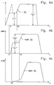
- Fig.4a, 4b, 4c characterize the time course of the injection process
- Fig.4a the flow size for the solenoid valve 5
- Fig.4b the stroke of the solenoid valve 5 (ie the pilot valve stem 70 and the armature 75)
- Fig.4c the stroke of the Show control piston 30 and thus also the nozzle needle 24.
- the high-pressure part of the fuel injection valve 1 i.e. in the fuel supply bore 40, in both high pressure supply lines 41, 42, in the annular spaces 29, 55 and in the control chamber 60 the same high pressure or injection pressure, which can be up to over 1500 bar.
- the fuel injector 1 is in the closed position shown in FIGS. 1, 2 and 3a. According to FIG. 3a, the upper end face 85 of the armature 75 is at a distance L from the lower pole face 83 of the magnet inner part 73.
- the control system issues a first electrical pulse to the solenoid valve 5.
- the coil 74 is energized. If the current reaches a certain size I1 (see FIG. 4 a), the force of the spring 97 holding the armature 75 with the pilot valve stem 70 in the closed position is overcome and the armature 75 is attracted. The start of this movement is designated in Figure 4a and 4b with time t1. Together with the pilot valve stem 70, it performs a first stroke H1 (see FIGS.
- the drop in pressure causes the nozzle needle 24 and also the control piston 30 to be raised from the nozzle needle seat 20 by the fuel pressure prevailing in the annular space 29 and acting on the shoulder 22 and begins to rise to move (see time t2 in Fig.4c).
- the injection openings 21 are released and a first phase of the injection process takes place with the nozzle needle 24 opening slowly.
- the control system issues a second electrical pulse to the solenoid valve 5.
- the armature 75 is tightened together with the pilot valve stem 70 in accordance with the larger current I2 according to FIG 84 of the pilot valve stem 70 to move upward.
- the flange 80 of the stroke stop 78 is raised by the shoulder 81, the stroke stop 78 is pressed into the interior of the solenoid valve inner part 73 until the part 76 of the pilot valve stem 70 receiving the armature 75 rests with its shoulder surface 84 on the inner part 73.
- the pilot valve stem 70 with the armature 75 executes the second stroke designated H2 in FIGS. 3b and 4b.
- the end 71 of the pilot valve stem 70 also moves farther from the end face 62 of the guide element 50 by the stroke H2, as a result of which the cross section of the fuel flow increases, the pressure drop in the control chamber 60 is accelerated, and the nozzle needle 24 is moved upward more quickly (from time t4 in Fig.4b and 4c). There is a second phase of the injection process with rapid opening of the nozzle needle 24.
- the solenoid valve 5 responds quickly when the current is switched off.
- the closing position of the Fuel injector 1 can be set.
- the engine's operating behavior is significantly improved with regard to noise and pollutant emissions.
- the amount of fuel injected per unit of time can be controlled as required and optimally adapted to the conditions required by the engine.
- the time of the transition from the first to the second phase is freely selectable.
- a single-stage injection process can also be implemented by immediately setting the current to the second value I2.
- the current pulse can briefly be selected higher than I1 at the beginning, as shown in dashed lines in FIG.
- FIG. 5 shows a further fuel injection valve 2, which is provided with a solenoid valve 6 and with a control device 100.
- the lower part of the injection valve is not shown in the drawing; it can have the same shape as the corresponding part of the fuel injector 1 known from FIG. 1.
- the identical and identically acting parts already known from FIGS. 1 to 3c continue to be designated with the same reference numerals.
- the control device 100 has a control body 101 which is inserted into the central bore 31 of the housing 14 with a slight press fit or a tight sliding fit and is held by the outer part 17 of the solenoid valve 6 via its upper flange 102.
- a control piston 110 which is operatively connected to the nozzle needle (not shown here), is arranged so as to be axially displaceable in a closely sliding manner.
- the control piston 110 has a piston part 111 of reduced diameter.
- the corresponding sales area is designated 112.
- a control space 114 formed within the guide bore 31 is axially delimited by the shoulder surface 112 and by a lower seat surface 103 of the control body 101.
- An intermediate part 115 is likewise axially displaceable in the guide bore 31 or in the control chamber 114, which in the position shown is pressed against the lower seat surface 103 of the control body 101 by a preloaded spring 113 surrounding the piston part 111 with an upper seat surface 116.
- An annular space 117 is present between the intermediate part 115 and the guide bore 31.
- the control body 101 is provided with an annular circumferential groove 104, through which an annular space 105 connected to the upper high-pressure supply line 42 is formed.
- a number of bores 106 connect the annular space 105 to the seat surface 103.
- the annular space 105 or the circumferential groove 104 is also connected via a small bore 107 to a central bore 108 which is coaxial with the longitudinal axis of the fuel injector 2 and tapers into a control bore 109 at the top which corresponds functionally to the second control bore 60 according to FIG. 2 and likewise opens into the upper end face of the control body 101.
- This upper end face of the control body 101 is of the same design as that of the pressure control element 50 according to FIG. 2 and is therefore also denoted by 62; a precise configuration of this end face 62 is described in more detail below with reference to FIGS. 8 to 10.
- the intermediate part 115 has a small, centrally arranged control bore 118, which connects the control chamber 114 to the bore 108 and thus also via the small bore 107 to the high-pressure zone.
- the solenoid valve 6 in turn has an inner part 73 provided with the coil 74.
- a pilot valve stem 125 with its upper part 126 is arranged axially displaceably in the central bore 77 of the inner part 73.
- the pilot valve stem 125 has the same shape as the pilot valve stem 70 known from FIG. 2.
- the part receiving the armature 75 and the end end are therefore provided with the same reference numerals 76, 71 in FIG.
- a stop element 122 made of wear-resistant material is inserted in the bore 77 at the bottom; this stop element is preferably also used in the embodiment of the solenoid valve 5 shown in FIG. 2, but is not shown in FIG. 2.
- a pin 128 provided with a shoulder 129, to which the spring 97 biased by the adjusting screw 95 is assigned in the same way as in FIG.
- a stop plate 130 is arranged on the pin 128 and is pressed by the spring 90, the compressive force of which can be adjusted by the adjusting screw 88, against a spacer disk 132 arranged between the stop plate 130 and the shoulder 81.
- a distance corresponding to the first stroke H1 is present between an upper end face 127 of the pilot valve stem 125 or its part 126 and a lower end face 131 of the stop plate 130.
- the structure of the fuel injector 2 is as follows from the structure described:
- the injection process is essentially the same as in fuel injector 1 in two stages.
- the first current is applied to the solenoid valve 6, which causes the pilot valve stem 125 to be raised by the first stroke H1 against the force of the spring 97 until its upper end face 127 bears against the lower end face 131 of the spring 90 pressed down stop plate 130 comes.
- the size of the first stroke H1 is optionally determined with the thickness of the spacer disk 132.
- the force of the spring 90 is also overcome by increasing the current strength and the tightening force, and the pilot valve stem 125 connected to the armature 75 performs the second stroke H2, as a result of which the pressure drop in the control chamber 114 and the consequent movement of the nozzle needle be accelerated above.
- the second phase of the injection takes place.
- control system switches the power supply to Solenoid valve 6 interrupted, armature 75 with pilot valve stem 125 is moved downward by springs 90, 97 and the outlet of control bore 109 is closed by end 71.
- the pressure in the central bore 108 of the control body 101 increases and, together with the fuel pressure present in the bore 106, is able to momentarily move the intermediate part 115 away from the lower seat 103 of the control body 101 against the force of the spring 113.
- a larger flow cross-section of the fuel is released via the bores 106 and the annular space 117 than only via the control bore 118 to the control space 114, which causes the injection openings to close abruptly via the control piston 110.
- the control device 100 corresponds essentially to the control device known from EP-PS 0 426 205, in which a rapid and clean completion of the injection process is realized in the same way.
- FIG. 6 shows a further exemplary embodiment of a solenoid valve 7, which could also be used both in cooperation with the control device 15 of the fuel injection valve 1 according to FIGS. 1 and 2 and also in cooperation with the control device 100 of the fuel injection valve 2 according to FIG. 5.
- the pilot valve stem of the solenoid valve 7 has essentially the same shape as that according to FIG. 5 and is therefore also designated 125.
- a valve head 141 is screwed in with a central, with the Pilot valve stem 125 is provided with coaxial bore 142.
- the bore 142 has an extension 143 at the bottom, in which a piston 145, which is inserted via a pin 146 in the pilot valve stem 125 and is axially displaceable with it, is arranged so as to slide closely.
- a spring 150 is arranged in a bore 147 of the piston 145 and is supported on a shoulder 148, which on the other hand is prestressed by an adjusting screw 151 screwed into the valve head 141 and provided with a guide pin 152.
- a spacer 153 is assigned to the adjusting screw 151.
- a lower space 157 is formed in the enlarged bore part 140 of the solenoid valve inner part 73, which is connected via a connecting bore 156 to the discharge space 65 belonging to the low-pressure part of the fuel injector.
- An upper space located above the piston 145 is designated 158 in FIG. This upper space 158 is connected to the lower space 157 via a throttle bore 159.
- FIGS. 7a, 7b and 7c which, like FIGS. 4a, 4b, 4c, show the course of the injection process over time with respect to the flow size, the solenoid valve stroke and the control piston or nozzle needle stroke, the functional configuration now becomes of the solenoid valve 7 explained in Fig.6.
- the control system issues an electrical control pulse to the solenoid valve 7.
- the initially slow movement of the pilot valve stem 125 and the nozzle needle is accelerated after the fuel has been completely displaced from the space 158. If the power supply to the solenoid valve 7 is interrupted by the control in order to end the injection process, the pilot valve stem 125 with the armature 75, to which no more tightening force is now exerted, is pressed together with the piston 145 by the spring 150 back into the closed position . This brings the volume of the upper room 158 to its original size, which leads to a momentary negative pressure in the room 158; due to the pressure difference between the lower space 157 and the upper space 158, the fuel liquid passes through the throttle bore 159 back into the upper space 158.
- the end face 62 is provided with an annular relief recess or end groove 163, by means of which an annular sealing surface 162 of smaller diameter surrounding the outlet of the control bore 109 is delimited.
- the outer diameter of the end groove 163 is smaller than the diameter of the end 71; as a result, a further, essentially annular seat surface 164 is available for the flat seat between the end 71 and the end face 62 (lying in the same plane as the sealing surface 162), which is only provided by two groove-shaped relief exits 165, possibly opening into the annular end face 163 is interrupted.
- the relief outlets 165 which are arranged symmetrically here and manufactured as a groove, extend beyond the diameter of the end 71. Both the forehead 163 and the relief outputs 165 can be produced by machining, by stamping, by electrical erosion or by chemical material removal.
- a small sealing surface is particularly exposed to the great mechanical stress when the outlet is closed abruptly. This strain is caused by the Arrangement of an additional seat surface 164 according to the invention, which in addition to the sealing surface 162 absorbs the mechanical forces, is considerably reduced.
Landscapes
- Engineering & Computer Science (AREA)
- Chemical & Material Sciences (AREA)
- Combustion & Propulsion (AREA)
- Mechanical Engineering (AREA)
- General Engineering & Computer Science (AREA)
- Physics & Mathematics (AREA)
- Fluid Mechanics (AREA)
- Electromagnetism (AREA)
- Fuel-Injection Apparatus (AREA)
Applications Claiming Priority (3)
| Application Number | Priority Date | Filing Date | Title |
|---|---|---|---|
| CH162895 | 1995-06-02 | ||
| CH162895 | 1995-06-02 | ||
| CH1628/95 | 1995-06-02 |
Publications (3)
| Publication Number | Publication Date |
|---|---|
| EP0745764A2 true EP0745764A2 (fr) | 1996-12-04 |
| EP0745764A3 EP0745764A3 (fr) | 1996-12-27 |
| EP0745764B1 EP0745764B1 (fr) | 2001-03-21 |
Family
ID=4214894
Family Applications (1)
| Application Number | Title | Priority Date | Filing Date |
|---|---|---|---|
| EP96107546A Expired - Lifetime EP0745764B1 (fr) | 1995-06-02 | 1996-05-21 | Soupape d'injection de combustible pour moteurs à combustion interne |
Country Status (5)
| Country | Link |
|---|---|
| US (2) | US5694903A (fr) |
| EP (1) | EP0745764B1 (fr) |
| JP (1) | JPH08326619A (fr) |
| AT (1) | ATE199966T1 (fr) |
| DE (1) | DE59606610D1 (fr) |
Cited By (15)
| Publication number | Priority date | Publication date | Assignee | Title |
|---|---|---|---|---|
| EP0829641A3 (fr) * | 1996-08-31 | 1998-10-21 | Isuzu Motors Limited | Dispositif d'injection de combustible pour moteurs |
| WO1999015779A1 (fr) * | 1997-09-23 | 1999-04-01 | Robert Bosch Gmbh | Soupape d'injection |
| DE19749001A1 (de) * | 1997-11-06 | 1999-05-27 | Daimler Chrysler Ag | Speichereinspritzsystem für eine mehrzylindrige Brennkraftmaschine |
| DE19938921A1 (de) * | 1999-08-17 | 2001-03-01 | Orange Gmbh | Einspritzventil für eine Verbrennungskraftmaschine |
| DE19939939A1 (de) * | 1999-08-23 | 2001-04-19 | Bosch Gmbh Robert | Injektor für ein Common-Rail-Einspritzsystem für Brennkraftmaschinen mit kompakter Bauweise |
| EP0949415A3 (fr) * | 1998-04-11 | 2002-06-12 | Robert Bosch Gmbh | Dispositif d'injection de combustible pour moteurs à combustion interne |
| DE19636088C2 (de) * | 1996-09-05 | 2003-02-06 | Avl Verbrennungskraft Messtech | Verfahren zur Steuerung der direkten Einspritzung von Kraftstoff |
| WO2003078828A1 (fr) * | 2002-03-15 | 2003-09-25 | Robert Bosch Gmbh | Systeme d'injection de carburant pour moteur a combustion interne |
| WO2004005703A1 (fr) * | 2002-07-03 | 2004-01-15 | Siemens Aktiengesellschaft | Procede de production d'un joint sur un injecteur et injecteur dote d'un joint haute pression ameliore |
| EP1134405A3 (fr) * | 2000-03-13 | 2004-11-17 | Denso Corporation | Structure améliorée d'un injecteur de carburant réglable quant aux caractéristiques du jet de carburant |
| DE10133682B4 (de) * | 2000-07-12 | 2008-08-07 | Denso Corp., Kariya | Kraftstoffeinspritzvorrichtung |
| WO2012113587A1 (fr) * | 2011-02-24 | 2012-08-30 | Robert Bosch Gmbh | Soupape de commande pour un injecteur de carburant, et injecteur de carburant |
| DE19738351B4 (de) * | 1996-09-02 | 2013-10-24 | Denso Corporation | Speicherkraftstoffeinspritzsystem |
| WO2016186822A1 (fr) * | 2015-05-20 | 2016-11-24 | Caterpillar Inc. | Injecteur de carburant à rampe commune |
| WO2019016398A1 (fr) * | 2017-07-20 | 2019-01-24 | Liebherr-Components Deggendorf Gmbh | Injecteur pour l'injection de carburant |
Families Citing this family (61)
| Publication number | Priority date | Publication date | Assignee | Title |
|---|---|---|---|---|
| US5954487A (en) * | 1995-06-23 | 1999-09-21 | Diesel Technology Company | Fuel pump control valve assembly |
| DE19619523A1 (de) * | 1996-05-15 | 1997-11-20 | Bosch Gmbh Robert | Kraftstoffeinspritzventil für Hochdruckeinspritzung |
| US5878720A (en) * | 1997-02-26 | 1999-03-09 | Caterpillar Inc. | Hydraulically actuated fuel injector with proportional control |
| US5860597A (en) * | 1997-03-24 | 1999-01-19 | Cummins Engine Company, Inc. | Injection rate shaping nozzle assembly for a fuel injector |
| GB9714647D0 (en) * | 1997-07-12 | 1997-09-17 | Lucas Ind Plc | Injector |
| GB9720003D0 (en) * | 1997-09-20 | 1997-11-19 | Lucas Ind Plc | Drive circuit |
| US6237570B1 (en) * | 1997-10-09 | 2001-05-29 | Denso Corporation | Accumulator fuel injection apparatus |
| US6199533B1 (en) | 1999-02-01 | 2001-03-13 | Cummins Engine Company, Inc. | Pilot valve controlled three-way fuel injection control valve assembly |
| DE69911670T2 (de) * | 1998-02-19 | 2004-08-12 | Delphi Technologies, Inc., Troy | Kraftstoffeinspritzventil |
| US5875764A (en) * | 1998-05-13 | 1999-03-02 | Siemens Aktiengesellschaft | Apparatus and method for valve control |
| US6302080B1 (en) | 1998-07-31 | 2001-10-16 | Denso Corporation | Fuel injection system having pre-injection and main injection |
| US6019091A (en) * | 1998-08-13 | 2000-02-01 | Diesel Technology Company | Control valve |
| US6079641A (en) * | 1998-10-13 | 2000-06-27 | Caterpillar Inc. | Fuel injector with rate shaping control through piezoelectric nozzle lift |
| JP2002529654A (ja) * | 1998-11-10 | 2002-09-10 | ガンサー−ハイドロマグ アーゲー | 内燃機関用燃料噴射バルブ |
| DE19859537A1 (de) * | 1998-12-22 | 2000-07-06 | Bosch Gmbh Robert | Kraftstoffeinspritzventil |
| US6173699B1 (en) | 1999-02-04 | 2001-01-16 | Caterpillar Inc. | Hydraulically-actuated fuel injector with electronically actuated spill valve |
| US6158419A (en) * | 1999-03-10 | 2000-12-12 | Diesel Technology Company | Control valve assembly for pumps and injectors |
| US6089470A (en) * | 1999-03-10 | 2000-07-18 | Diesel Technology Company | Control valve assembly for pumps and injectors |
| DE19921878C2 (de) * | 1999-05-12 | 2001-03-15 | Daimler Chrysler Ag | Kraftstoffeinspritzsystem für eine Brennkraftmaschine |
| DE19940292B4 (de) * | 1999-08-25 | 2008-03-06 | Robert Bosch Gmbh | Steuerventil für ein Kraftstoffeinspritzventil |
| DE60014813T2 (de) | 1999-08-31 | 2006-03-09 | Denso Corp., Kariya | Kraftstoffeinspritzvorrichtung |
| US6293231B1 (en) | 1999-09-29 | 2001-09-25 | Ingo Valentin | Free-piston internal combustion engine |
| US6293254B1 (en) * | 2000-01-07 | 2001-09-25 | Cummins Engine Company, Inc. | Fuel injector with floating sleeve control chamber |
| DE10002704A1 (de) * | 2000-01-22 | 2001-08-02 | Bosch Gmbh Robert | Einspritzeinrichtung und Verfahren zum Einspritzen von Fluid |
| DE10005013A1 (de) * | 2000-02-04 | 2001-08-09 | Bosch Gmbh Robert | Brennstoffeinspritzventil |
| US6279843B1 (en) | 2000-03-21 | 2001-08-28 | Caterpillar Inc. | Single pole solenoid assembly and fuel injector using same |
| US6499467B1 (en) | 2000-03-31 | 2002-12-31 | Cummins Inc. | Closed nozzle fuel injector with improved controllabilty |
| US6375098B1 (en) * | 2000-04-07 | 2002-04-23 | Delphi Technologies, Inc. | Injection valve for the fuel injection in an internal combustion engine |
| US6568369B1 (en) * | 2000-12-05 | 2003-05-27 | Caterpillar Inc | Common rail injector with separately controlled pilot and main injection |
| US6450778B1 (en) | 2000-12-07 | 2002-09-17 | Diesel Technology Company | Pump system with high pressure restriction |
| US6431472B1 (en) | 2000-12-21 | 2002-08-13 | Caterpillar Inc. | Fuel injector nozzle with outwardly opening check valve |
| DE10122256A1 (de) * | 2001-05-08 | 2002-11-21 | Bosch Gmbh Robert | Kraftstoff-Einspritzvorrichtung für Brennkraftmaschinen, insbesondere Common-Rail-Injektor, sowie Kraftstoffsystem und Brennkraftmaschine |
| ITTO20010970A1 (it) * | 2001-10-12 | 2003-04-12 | Fiat Ricerche | Inettore di combustibile per un motore a combustione interna. |
| US6684854B2 (en) | 2001-12-14 | 2004-02-03 | Caterpillar Inc | Auxiliary systems for an engine having two electrical actuators on a single circuit |
| DE10163693A1 (de) * | 2001-12-21 | 2003-07-10 | Orange Gmbh | Einspritzinjektor für Brennkraftmaschinen |
| EP1476652B1 (fr) * | 2002-02-22 | 2005-07-06 | CRT Common Rail Technologies AG | Soupape d'injection de carburant pour moteurs a combustion interne |
| EP1347168B1 (fr) * | 2002-03-18 | 2006-03-29 | L'orange Gmbh | Injecteur pour moteurs à combustion interne |
| DE10250130A1 (de) * | 2002-10-28 | 2004-03-04 | Robert Bosch Gmbh | Hochdruckeinspritzeinrichtung mit Druck- und Hubsteuerung |
| DE10320592A1 (de) * | 2003-05-08 | 2004-11-25 | Robert Bosch Gmbh | Förderpumpe, insbesondere Hochdruck-Kraftstoffpumpe für eine Brennkraftmaschine |
| ATE487057T1 (de) * | 2004-02-25 | 2010-11-15 | Ganser Hydromag | Brennstoffeinspritzventil für verbrennungskraftmaschinen |
| US6912998B1 (en) | 2004-03-10 | 2005-07-05 | Cummins Inc. | Piezoelectric fuel injection system with rate shape control and method of controlling same |
| US6978770B2 (en) * | 2004-05-12 | 2005-12-27 | Cummins Inc. | Piezoelectric fuel injection system with rate shape control and method of controlling same |
| DE102004049288A1 (de) * | 2004-10-09 | 2006-04-20 | Robert Bosch Gmbh | Kraftstoffinjektor mit formgeprägtem Ventilsitz zur Reduzierung der Ankerhubdrift |
| JP4650395B2 (ja) * | 2006-11-02 | 2011-03-16 | 株式会社デンソー | 燃料噴射弁 |
| DE102007052361A1 (de) * | 2007-11-02 | 2009-05-07 | Robert Bosch Gmbh | Elastischer Sitz für Schaltventile |
| JP5039524B2 (ja) * | 2007-12-05 | 2012-10-03 | 三菱重工業株式会社 | 蓄圧式燃料噴射装置の燃料噴射弁 |
| DE102008044096A1 (de) * | 2008-11-27 | 2010-06-02 | Robert Bosch Gmbh | Verfahren zur Herstellung von Drosselbohrungen mit niedrigem Kaviationsumschlagpunkt |
| DE102009002128A1 (de) * | 2009-04-02 | 2010-10-14 | Robert Bosch Gmbh | Kraftstoffeinspritzvorrichtung |
| DE102010040581A1 (de) * | 2010-02-24 | 2011-08-25 | Robert Bosch GmbH, 70469 | Kraftstoffinjektor sowie Verfahren zur Herstellung und/oder Montage einer Düsennadel-Baugruppe |
| EP2444651B1 (fr) * | 2010-10-19 | 2013-07-10 | Continental Automotive GmbH | Ensemble de soupape pour soupape d'injection et soupape d'injection |
| US9291138B2 (en) | 2011-11-01 | 2016-03-22 | Cummins Inc. | Fuel injector with injection control valve assembly |
| JP5965253B2 (ja) | 2012-02-20 | 2016-08-03 | 株式会社デンソー | 燃料噴射弁 |
| DE102012203124A1 (de) * | 2012-02-29 | 2013-08-29 | Robert Bosch Gmbh | Einspritzventil |
| CN103133205B (zh) * | 2013-03-14 | 2014-11-26 | 天津大学 | 双通道压电喷油器 |
| DE102013212140A1 (de) * | 2013-06-25 | 2015-01-08 | Robert Bosch Gmbh | Steuerventil |
| EP2896813B1 (fr) | 2014-01-17 | 2018-01-10 | Continental Automotive GmbH | Soupape d'injection de carburant pour moteurs à combustion interne |
| US10077748B2 (en) * | 2014-12-23 | 2018-09-18 | Cummins Inc. | Fuel injector for common rail |
| JP6507890B2 (ja) * | 2015-07-02 | 2019-05-08 | 株式会社デンソー | 燃料噴射弁 |
| DE102017207685A1 (de) * | 2017-05-08 | 2018-11-08 | Robert Bosch Gmbh | Verfahren zum Ansteuern mindestens eines Magnetventils |
| CN114458505B (zh) * | 2022-03-09 | 2023-02-14 | 哈尔滨工程大学 | 一种带有多级阻尼缓冲的高速电磁阀 |
| CN119435264A (zh) * | 2024-08-23 | 2025-02-14 | 山西柴油机工业有限责任公司 | 一种分体式超高压力共轨喷油器控制阀 |
Family Cites Families (18)
| Publication number | Priority date | Publication date | Assignee | Title |
|---|---|---|---|---|
| FR985567A (fr) * | 1949-02-23 | 1951-07-20 | Injecteur accumulateur pour moteur à allumage par combustion | |
| DE1026572B (de) * | 1956-11-16 | 1958-03-20 | Friedmann & Maier Ag | Einspritzduese fuer Einspritzbrennkraftmaschinen |
| US4603671A (en) * | 1983-08-17 | 1986-08-05 | Nippon Soken, Inc. | Fuel injector for an internal combustion engine |
| JPS60108560A (ja) * | 1983-11-16 | 1985-06-14 | Toyota Central Res & Dev Lab Inc | 燃料噴射制御法及び装置 |
| US4871161A (en) * | 1984-09-11 | 1989-10-03 | Levi Strauss & Co. | Separating and feeding garment parts |
| EP0426205B1 (fr) * | 1985-12-02 | 1993-07-21 | Marco Alfredo Ganser | Dispositif de commande d'injecteurs de combustible actionnés électro-hydrauliquement |
| CH668621A5 (de) * | 1986-01-22 | 1989-01-13 | Dereco Dieselmotoren Forschung | Kraftstoffeinspritzanlage fuer eine brennkraftmaschine. |
| ATE98340T1 (de) * | 1986-09-25 | 1993-12-15 | Ganser Hydromag | Elektronisch gesteuertes einspritzsystem. |
| DE3906205A1 (de) * | 1989-02-28 | 1990-08-30 | Daimler Benz Ag | Einspritzvorrichtung fuer eine luftverdichtende brennkraftmaschine mit einer die vor- und haupteinspritzung bewirkenden einspritzduese, insbesondere drosselzapfenduese |
| US5156132A (en) * | 1989-04-17 | 1992-10-20 | Nippondenso Co., Ltd. | Fuel injection device for diesel engines |
| DE4122517A1 (de) * | 1991-07-08 | 1993-01-21 | Bosch Gmbh Robert | Elektromagnetventil |
| IT1250846B (it) * | 1991-10-11 | 1995-04-21 | Weber Srl | Valvola dosatrice e polverizzatrice di carburante ad azionamento elettromagnetico avente dimensioni molto ridotte |
| US5472142A (en) * | 1992-08-11 | 1995-12-05 | Nippondenso Co., Ltd. | Accumulator fuel injection apparatus |
| IT227711Y1 (it) * | 1992-12-29 | 1997-12-15 | Elasis Sistema Ricerca Fiat | Valvola di dosaggio a comando elettromagnetico per un iniettore di combustibile |
| DE4302668A1 (de) * | 1993-01-30 | 1994-08-04 | Bosch Gmbh Robert | Kraftstoffeinspritzeinrichtung für Brennkraftmaschinen |
| JPH08158981A (ja) * | 1994-12-02 | 1996-06-18 | Nippondenso Co Ltd | 燃料噴射装置 |
| US5671715A (en) * | 1995-04-27 | 1997-09-30 | Nipon Soken, Inc. | Fuel injection device |
| US5526791A (en) * | 1995-06-07 | 1996-06-18 | Diesel Technology Company | High-pressure electromagnetic fuel injector |
-
1996
- 1996-05-21 DE DE59606610T patent/DE59606610D1/de not_active Expired - Fee Related
- 1996-05-21 AT AT96107546T patent/ATE199966T1/de not_active IP Right Cessation
- 1996-05-21 EP EP96107546A patent/EP0745764B1/fr not_active Expired - Lifetime
- 1996-06-03 US US08/657,252 patent/US5694903A/en not_active Expired - Lifetime
- 1996-06-03 JP JP8162295A patent/JPH08326619A/ja active Pending
-
1997
- 1997-06-10 US US08/872,077 patent/US5775301A/en not_active Expired - Lifetime
Cited By (19)
| Publication number | Priority date | Publication date | Assignee | Title |
|---|---|---|---|---|
| EP0829641A3 (fr) * | 1996-08-31 | 1998-10-21 | Isuzu Motors Limited | Dispositif d'injection de combustible pour moteurs |
| DE19738351B4 (de) * | 1996-09-02 | 2013-10-24 | Denso Corporation | Speicherkraftstoffeinspritzsystem |
| DE19636088C2 (de) * | 1996-09-05 | 2003-02-06 | Avl Verbrennungskraft Messtech | Verfahren zur Steuerung der direkten Einspritzung von Kraftstoff |
| WO1999015779A1 (fr) * | 1997-09-23 | 1999-04-01 | Robert Bosch Gmbh | Soupape d'injection |
| DE19749001A1 (de) * | 1997-11-06 | 1999-05-27 | Daimler Chrysler Ag | Speichereinspritzsystem für eine mehrzylindrige Brennkraftmaschine |
| EP0949415A3 (fr) * | 1998-04-11 | 2002-06-12 | Robert Bosch Gmbh | Dispositif d'injection de combustible pour moteurs à combustion interne |
| DE19938921A1 (de) * | 1999-08-17 | 2001-03-01 | Orange Gmbh | Einspritzventil für eine Verbrennungskraftmaschine |
| DE19938921B4 (de) * | 1999-08-17 | 2004-02-19 | L'orange Gmbh | Einspritzventil für eine Verbrennungskraftmaschine |
| DE19939939A1 (de) * | 1999-08-23 | 2001-04-19 | Bosch Gmbh Robert | Injektor für ein Common-Rail-Einspritzsystem für Brennkraftmaschinen mit kompakter Bauweise |
| EP1134405A3 (fr) * | 2000-03-13 | 2004-11-17 | Denso Corporation | Structure améliorée d'un injecteur de carburant réglable quant aux caractéristiques du jet de carburant |
| DE10133682B4 (de) * | 2000-07-12 | 2008-08-07 | Denso Corp., Kariya | Kraftstoffeinspritzvorrichtung |
| WO2003078828A1 (fr) * | 2002-03-15 | 2003-09-25 | Robert Bosch Gmbh | Systeme d'injection de carburant pour moteur a combustion interne |
| WO2004005703A1 (fr) * | 2002-07-03 | 2004-01-15 | Siemens Aktiengesellschaft | Procede de production d'un joint sur un injecteur et injecteur dote d'un joint haute pression ameliore |
| WO2012113587A1 (fr) * | 2011-02-24 | 2012-08-30 | Robert Bosch Gmbh | Soupape de commande pour un injecteur de carburant, et injecteur de carburant |
| CN103392064A (zh) * | 2011-02-24 | 2013-11-13 | 罗伯特·博世有限公司 | 用于燃料喷射器的控制阀及燃料喷射器 |
| WO2016186822A1 (fr) * | 2015-05-20 | 2016-11-24 | Caterpillar Inc. | Injecteur de carburant à rampe commune |
| CN107636298A (zh) * | 2015-05-20 | 2018-01-26 | 卡特彼勒公司 | 共轨燃料喷射器 |
| WO2019016398A1 (fr) * | 2017-07-20 | 2019-01-24 | Liebherr-Components Deggendorf Gmbh | Injecteur pour l'injection de carburant |
| US11319913B2 (en) | 2017-07-20 | 2022-05-03 | Liebherr-Components Deggendorf Gmbh | Injector for injecting fuel |
Also Published As
| Publication number | Publication date |
|---|---|
| JPH08326619A (ja) | 1996-12-10 |
| EP0745764B1 (fr) | 2001-03-21 |
| US5775301A (en) | 1998-07-07 |
| EP0745764A3 (fr) | 1996-12-27 |
| ATE199966T1 (de) | 2001-04-15 |
| US5694903A (en) | 1997-12-09 |
| DE59606610D1 (de) | 2001-04-26 |
Similar Documents
| Publication | Publication Date | Title |
|---|---|---|
| EP0745764B1 (fr) | Soupape d'injection de combustible pour moteurs à combustion interne | |
| EP0925440B1 (fr) | Injecteur de carburant | |
| EP1991773B1 (fr) | Soupape d'injection de carburant pour moteurs a combustion interne | |
| EP0949415B1 (fr) | Dispositif d'injection de combustible pour moteurs à combustion interne | |
| DE69717744T2 (de) | Kraftstoffeinspritzvorrichtung für Brennkraftmaschinen | |
| EP1252432B1 (fr) | Dispositif d'injection de carburant a commande directe pour un moteur a combustion interne a pistons | |
| EP0807757A1 (fr) | Injecteur de combustible pour moteur à combustion interne | |
| DE10326259A1 (de) | Injektor für Kraftstoff-Einspritzsysteme von Brennkraftmaschinen, insbesondere von direkteinspritzenden Dieselmotoren | |
| EP1476652A1 (fr) | Soupape d'injection de carburant pour moteurs a combustion interne | |
| EP0050710A1 (fr) | Installation d'injection de carburant | |
| WO1999018349A1 (fr) | Soupape d'injection a commande directe, en particulier soupape d'injection de carburant | |
| DE3311138A1 (de) | Kraftstoffeinspritzanlage fuer eine brennkraftmaschine | |
| DE19860397A1 (de) | Kraftstoffeinspritzvorrichtung für Brennkraftmaschinen | |
| EP1151192A1 (fr) | Soupape d'injection de carburant pour moteurs a combustion interne | |
| DE19947772A1 (de) | Einspritzventil, insb. für Common-Rail-Einspritzsysteme | |
| EP2022975B1 (fr) | Injecteur | |
| DE10038995A1 (de) | Verfahren und Vorrichtung zur Steuerung der Kraftstoffzumessung in einer Brennkraftmaschine | |
| EP1210512B1 (fr) | Injecteur | |
| DE19963926A1 (de) | Steuerventil für eine Kraftstoffeinspritzvorrichtung für Brennkraftmaschinen mit verstellbarem Hubanschlag | |
| EP1836385B1 (fr) | Soupape d'injection de combustible a multiplication de pression | |
| DE10063261A1 (de) | Brennstoffeinspritzventil | |
| EP1313944A1 (fr) | Systeme d'injection de carburant pour moteurs a combustion interne | |
| EP1176306A2 (fr) | Système d'injection de combustible pour moteurs à combustion interne | |
| DE19834763C2 (de) | Pumpe-Leitung-Düse-System | |
| EP1328726A1 (fr) | Systeme d'injection de carburant pour moteurs a combustion interne |
Legal Events
| Date | Code | Title | Description |
|---|---|---|---|
| PUAI | Public reference made under article 153(3) epc to a published international application that has entered the european phase |
Free format text: ORIGINAL CODE: 0009012 |
|
| PUAL | Search report despatched |
Free format text: ORIGINAL CODE: 0009013 |
|
| AK | Designated contracting states |
Kind code of ref document: A2 Designated state(s): AT CH DE FR GB IT LI SE |
|
| AK | Designated contracting states |
Kind code of ref document: A3 Designated state(s): AT CH DE FR GB IT LI SE |
|
| 17P | Request for examination filed |
Effective date: 19970611 |
|
| 17Q | First examination report despatched |
Effective date: 19990317 |
|
| R17P | Request for examination filed (corrected) |
Effective date: 19970611 |
|
| GRAG | Despatch of communication of intention to grant |
Free format text: ORIGINAL CODE: EPIDOS AGRA |
|
| GRAG | Despatch of communication of intention to grant |
Free format text: ORIGINAL CODE: EPIDOS AGRA |
|
| GRAH | Despatch of communication of intention to grant a patent |
Free format text: ORIGINAL CODE: EPIDOS IGRA |
|
| GRAH | Despatch of communication of intention to grant a patent |
Free format text: ORIGINAL CODE: EPIDOS IGRA |
|
| GRAA | (expected) grant |
Free format text: ORIGINAL CODE: 0009210 |
|
| AK | Designated contracting states |
Kind code of ref document: B1 Designated state(s): AT CH DE FR GB IT LI SE |
|
| REF | Corresponds to: |
Ref document number: 199966 Country of ref document: AT Date of ref document: 20010415 Kind code of ref document: T |
|
| ITF | It: translation for a ep patent filed | ||
| REG | Reference to a national code |
Ref country code: CH Ref legal event code: NV Representative=s name: PATENTANWAELTE SCHAAD, BALASS, MENZL & PARTNER AG Ref country code: CH Ref legal event code: EP |
|
| GBT | Gb: translation of ep patent filed (gb section 77(6)(a)/1977) |
Effective date: 20010321 |
|
| REF | Corresponds to: |
Ref document number: 59606610 Country of ref document: DE Date of ref document: 20010426 |
|
| PG25 | Lapsed in a contracting state [announced via postgrant information from national office to epo] |
Ref country code: SE Free format text: LAPSE BECAUSE OF FAILURE TO SUBMIT A TRANSLATION OF THE DESCRIPTION OR TO PAY THE FEE WITHIN THE PRESCRIBED TIME-LIMIT Effective date: 20010621 |
|
| ET | Fr: translation filed | ||
| REG | Reference to a national code |
Ref country code: GB Ref legal event code: IF02 |
|
| PLBE | No opposition filed within time limit |
Free format text: ORIGINAL CODE: 0009261 |
|
| STAA | Information on the status of an ep patent application or granted ep patent |
Free format text: STATUS: NO OPPOSITION FILED WITHIN TIME LIMIT |
|
| 26N | No opposition filed | ||
| PGFP | Annual fee paid to national office [announced via postgrant information from national office to epo] |
Ref country code: DE Payment date: 20050510 Year of fee payment: 10 |
|
| PGFP | Annual fee paid to national office [announced via postgrant information from national office to epo] |
Ref country code: FR Payment date: 20050512 Year of fee payment: 10 |
|
| PGFP | Annual fee paid to national office [announced via postgrant information from national office to epo] |
Ref country code: AT Payment date: 20050520 Year of fee payment: 10 |
|
| PG25 | Lapsed in a contracting state [announced via postgrant information from national office to epo] |
Ref country code: AT Free format text: LAPSE BECAUSE OF NON-PAYMENT OF DUE FEES Effective date: 20060521 |
|
| PGFP | Annual fee paid to national office [announced via postgrant information from national office to epo] |
Ref country code: IT Payment date: 20060531 Year of fee payment: 11 |
|
| PG25 | Lapsed in a contracting state [announced via postgrant information from national office to epo] |
Ref country code: DE Free format text: LAPSE BECAUSE OF NON-PAYMENT OF DUE FEES Effective date: 20061201 |
|
| REG | Reference to a national code |
Ref country code: FR Ref legal event code: ST Effective date: 20070131 |
|
| PG25 | Lapsed in a contracting state [announced via postgrant information from national office to epo] |
Ref country code: FR Free format text: LAPSE BECAUSE OF NON-PAYMENT OF DUE FEES Effective date: 20060531 |
|
| PG25 | Lapsed in a contracting state [announced via postgrant information from national office to epo] |
Ref country code: IT Free format text: LAPSE BECAUSE OF NON-PAYMENT OF DUE FEES Effective date: 20070521 |
|
| PGFP | Annual fee paid to national office [announced via postgrant information from national office to epo] |
Ref country code: GB Payment date: 20150521 Year of fee payment: 20 Ref country code: CH Payment date: 20150521 Year of fee payment: 20 |
|
| REG | Reference to a national code |
Ref country code: CH Ref legal event code: PL |
|
| REG | Reference to a national code |
Ref country code: GB Ref legal event code: PE20 Expiry date: 20160520 |
|
| PG25 | Lapsed in a contracting state [announced via postgrant information from national office to epo] |
Ref country code: GB Free format text: LAPSE BECAUSE OF EXPIRATION OF PROTECTION Effective date: 20160520 |