EP0745976B1 - Verfahren und Vorrichtung zur Trackingkorrektur und optische Platte dafür - Google Patents
Verfahren und Vorrichtung zur Trackingkorrektur und optische Platte dafür Download PDFInfo
- Publication number
- EP0745976B1 EP0745976B1 EP96106684A EP96106684A EP0745976B1 EP 0745976 B1 EP0745976 B1 EP 0745976B1 EP 96106684 A EP96106684 A EP 96106684A EP 96106684 A EP96106684 A EP 96106684A EP 0745976 B1 EP0745976 B1 EP 0745976B1
- Authority
- EP
- European Patent Office
- Prior art keywords
- region
- amplitude
- tracking
- signal
- wobble signal
- Prior art date
- Legal status (The legal status is an assumption and is not a legal conclusion. Google has not performed a legal analysis and makes no representation as to the accuracy of the status listed.)
- Expired - Lifetime
Links
- 230000003287 optical effect Effects 0.000 title claims description 102
- 238000000034 method Methods 0.000 title claims description 30
- 230000004044 response Effects 0.000 claims description 6
- 238000001514 detection method Methods 0.000 description 17
- 239000004065 semiconductor Substances 0.000 description 5
- 230000008859 change Effects 0.000 description 4
- 230000032683 aging Effects 0.000 description 3
- 230000004075 alteration Effects 0.000 description 3
- 230000003321 amplification Effects 0.000 description 3
- 230000003750 conditioning effect Effects 0.000 description 3
- 238000003199 nucleic acid amplification method Methods 0.000 description 3
- 230000008569 process Effects 0.000 description 3
- 230000000694 effects Effects 0.000 description 1
- 230000009191 jumping Effects 0.000 description 1
- 230000010287 polarization Effects 0.000 description 1
- 230000009467 reduction Effects 0.000 description 1
- 230000000630 rising effect Effects 0.000 description 1
Images


Classifications
-
- G—PHYSICS
- G11—INFORMATION STORAGE
- G11B—INFORMATION STORAGE BASED ON RELATIVE MOVEMENT BETWEEN RECORD CARRIER AND TRANSDUCER
- G11B7/00—Recording or reproducing by optical means, e.g. recording using a thermal beam of optical radiation by modifying optical properties or the physical structure, reproducing using an optical beam at lower power by sensing optical properties; Record carriers therefor
- G11B7/24—Record carriers characterised by shape, structure or physical properties, or by the selection of the material
- G11B7/2407—Tracks or pits; Shape, structure or physical properties thereof
- G11B7/24073—Tracks
- G11B7/24082—Meandering
-
- G—PHYSICS
- G11—INFORMATION STORAGE
- G11B—INFORMATION STORAGE BASED ON RELATIVE MOVEMENT BETWEEN RECORD CARRIER AND TRANSDUCER
- G11B7/00—Recording or reproducing by optical means, e.g. recording using a thermal beam of optical radiation by modifying optical properties or the physical structure, reproducing using an optical beam at lower power by sensing optical properties; Record carriers therefor
- G11B7/08—Disposition or mounting of heads or light sources relatively to record carriers
- G11B7/09—Disposition or mounting of heads or light sources relatively to record carriers with provision for moving the light beam or focus plane for the purpose of maintaining alignment of the light beam relative to the record carrier during transducing operation, e.g. to compensate for surface irregularities of the latter or for track following
- G11B7/0901—Disposition or mounting of heads or light sources relatively to record carriers with provision for moving the light beam or focus plane for the purpose of maintaining alignment of the light beam relative to the record carrier during transducing operation, e.g. to compensate for surface irregularities of the latter or for track following for track following only
- G11B7/0904—Dithered tracking systems
-
- G—PHYSICS
- G11—INFORMATION STORAGE
- G11B—INFORMATION STORAGE BASED ON RELATIVE MOVEMENT BETWEEN RECORD CARRIER AND TRANSDUCER
- G11B7/00—Recording or reproducing by optical means, e.g. recording using a thermal beam of optical radiation by modifying optical properties or the physical structure, reproducing using an optical beam at lower power by sensing optical properties; Record carriers therefor
- G11B7/08—Disposition or mounting of heads or light sources relatively to record carriers
- G11B7/09—Disposition or mounting of heads or light sources relatively to record carriers with provision for moving the light beam or focus plane for the purpose of maintaining alignment of the light beam relative to the record carrier during transducing operation, e.g. to compensate for surface irregularities of the latter or for track following
- G11B7/0945—Methods for initialising servos, start-up sequences
-
- G—PHYSICS
- G11—INFORMATION STORAGE
- G11B—INFORMATION STORAGE BASED ON RELATIVE MOVEMENT BETWEEN RECORD CARRIER AND TRANSDUCER
- G11B7/00—Recording or reproducing by optical means, e.g. recording using a thermal beam of optical radiation by modifying optical properties or the physical structure, reproducing using an optical beam at lower power by sensing optical properties; Record carriers therefor
- G11B7/08—Disposition or mounting of heads or light sources relatively to record carriers
- G11B7/09—Disposition or mounting of heads or light sources relatively to record carriers with provision for moving the light beam or focus plane for the purpose of maintaining alignment of the light beam relative to the record carrier during transducing operation, e.g. to compensate for surface irregularities of the latter or for track following
- G11B7/094—Methods and circuits for servo offset compensation
Definitions
- the present invention relates to a method and an apparatus for carrying out a tracking correction of a light beam projected onto an optical recording medium in accordance with the precharacterizing parts of independent claims 1, 4, and 10 and to an optical disk for use therein.
- Lands and grooves between the lands are configured on some optical disks, and the tracking of a light beam with respect to such an optical disk is performed by making effective use of such a specific configuration.
- Both side walls, or one side wall, of the groove to be tracked are wobbled in a radial direction in the conventional optical disk, so that information, such as address information and information on the control of rotation, is recorded in accordance with such wabbled walls of the groove.
- the tracking is carried out in accordance with such wobbled walls of the groove.
- Japanese Publication for Unexamined Patent Application No.5-314538/1993 proposes an optical disk wherein only one side wall of a groove is wabbled so that address information is recorded.
- a frequency of a wobble signal is set so as not to be coincident with a frequency band for a tracking servo. Only wobbled frequency components of a wabble signal frequency are extracted from a tracking error signal by a band-pass filter, so that address information of a track which is being scanned by a light beam is reproduced.
- Japanese Publication for Unexamined Patent Application No.4-184718/1992 proposes an optical disk device for carrying out soft-formatting for use with an optical disk wherein a part of a groove has both side walls wobbled. With such an arrangement, the soft-formatting is carried out on the basis of a wobble signal, which is contained in the tracking error signal.
- a light beam is projected from a semiconductor laser 103 onto an optical disk 106 through a beam splitter 104 and an objective lens 105.
- the light beam reflected from the optical disk 106 is again transmitted through the objective lens 105, reflected by the beam splitter 104, and directed toward a two-division photodetector 107.
- Two signals detected by the two-division photodetector 107 are differential-amplified by a differential amplifier 108, and a tracking error signal is generated.
- the light beam from the semiconductor laser 103 is quenched during correcting the tracking error signal, so that an electric offset contained in the tracking error signal is eliminated.
- an adder 111 an offset voltage which is adjusted by a variable resistor 110 is added to an output signal of the differential amplifier 108, so that the offset voltage of the tracking error signal becomes zero.
- the recording medium which is described in US-A-4,866,688 comprises a pre-groove and prefabricated wabbled digital pits.
- the wobbled pits may have the same depth as the pre-groove.
- the groove and the wobbled pits may be regarded as an interrupted track having digitally wobbled side walls in a first region and a second region.
- the wobble frequency is outside the frequency band of the servo system as its purpose is to correct a DC offset in the tracking error signal.
- the amplitudes of the wobble signals are obtained for the first and second regions and the tracking error signal is corrected in such a way that the two amplitudes are substantially equal.
- the object of the present invention is to provide a tracking correction method and apparatus, for correcting a tracking deviation caused by an error in conditioning optical parts and an aberration of optical elements, and a change due to aging, and to provide an optical disk for use with such method and apparatus.
- either a tracking error signal or a total signal is obtained by carrying out the tracking of the light beam projected on the first region.
- the light beam for example, tracks off-center to the wobbled side wall
- the amplitude of the wobble signal in the tracking error signal or the total signal is great in comparison with that when the light beam tracks the center of a groove.
- the first amplitude of the wobble signal derived from the first region becomes greater than a desired value.
- the light beam tracks off-center to the non-wabbled side wall, because the wabbled side wall is opposite to that in the first region. Since the light beam is farther from the wobbled side wall, it is hardly affected by the wabbled side wall. Accordingly, the second amplitude of the wobble signal derived from the second region is smaller than the desired value.
- the comparison between the first and second amplitude is conducted and a correction signal which varies depending on the amplitude difference is supplied to the wobble signal so that the first and second amplitude become substantially equal, thereby enabling to correct the tracking. This causes the light beam to fall on the center of the groove in the tracking direction.
- the frequency band of the wabble signal is different from a tracking servo frequency band, the tracking is not affected by the wabble signal, i.e., it is possible to correct the deviation of the light beam from the groove center caused by an conditioning error and an aberration of optical elements, and a change due to aging.
- a tracking error signal is outputted by the signal detector and is sent to the amplitude detector. Then, the first amplitude of a wobble signal in the tracking error signal is detected by the amplitude detector, and is sent to the comparator.
- a second amplitude derived from the second region is sent to the comparator in the same manner as is the case with the first amplitude.
- the first and the second amplitude are compared by the comparator, the tracking error signal is corrected by the corrector so that the first and second amplitude are substantially equal.
- the light beam is made to fall on the center of a groove in the tracking direction.
- the received light amounts are added and converted into an electric signal which is outputted as a total signal.
- the total signal is used instead of the tracking error signal so as to obtain a wobble signal. the same effects as mentioned above are obtained with such an arrangement.
- an optical disk according to claim 16 is provided. Therefore, if the light beam performs the tracking off the center of a groove in the tracking direction, the amplitude of the wobble signals in either the tracking error signal or the total signal are different in the respective first and second regions, thereby enabling the tracking correction based on the detected amplitude. Note that since the frequency band of the wabble signal is different from a tracking servo frequency band, the tracking is not affected by the wobble signal.
- the tracks composed of such grooves are provided on the optical disk in a spiral form or in a concentric form, the first and the second regions may be provided on one track without interruptions. Accordingly, a track access operation is unnecessary and the tracking correction operation can be carried out quickly.
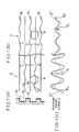
- Figure 1 (a) is a cross sectional view illustrating an optical recording medium for use in a tracking correction method of the first embodiment in accordance with the present invention.
- Figure 1 (b) is a plan view illustrating two types of grooves on the optical recording medium.
- Figure 1 (c) is an explanatory view illustrating amplitude of a wabble signal contained in a tracking error signal of the optical recording medium.
- Figure 2 is a view illustrating an arrangement of a tracking correction apparatus for carrying out the tracking correction method.
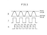
- Figure 3 is a timing chart of the tracking correction apparatus.
- Figure 4 is a flow chart illustrating the tracking correction method.
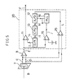
- Figure 5 is a view illustrating another arrangement of the tracking correction apparatus.
- Figure 6 is a view illustrating another arrangement of the tracking correction apparatus.
- Figure 7 is a view illustrating another arrangement of the tracking correction apparatus.
- Figure 8 is a view illustrating another arrangement of the tracking correction apparatus.
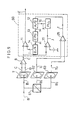
- Figure 9 is a view illustrating an arrangement wherein the tracking correction apparatus of Figure 5 is adopted to an magneto-optical recording-reproducing apparatus.
- Figure 10 is a view illustrating an arrangement wherein the above-mentioned optical recording medium has an optical disk having a tracking correction region.
- Figure 11 (a) is a cross sectional view illustrating how lands and grooves are provided in a data recording region of the optical disk.
- Figure 11 (b) is a plan view illustrating the data recording region.
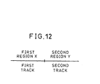
- Figure 12 is an explanatory view illustrating how first and second regions are provided on the optical disk.
- Figure 13 is a flow chart illustrating a tracking correction operation in case where the optical disk is employed.
- Figure 14 is a view illustrating an arrangement of moving means for moving an optical head.
- Figure 15 (a) is an explanatory view illustrating how first and second regions are provided on an optical disk in the third embodiment of the present invention.
- Figure 15 (b) is an explanatory view illustrating another arrangement of first and second regions.
- Figure 16 is a view illustrating an arrangement of a conventional tracking correction apparatus.
- a tracking correction method of the present embodiment is for correcting a tracking error signal which is obtained, for example, in accordance with the "push-pull" amplification method.
- An optical recording medium of the present embodiment as shown in Figures 1 (a) and 1(b), has grooves 1 and lands 2.
- the groove 1 is provided between the two lands 2.
- Wabbled in the first region X is a side wall 1a on the lower side of the groove 1 in Figure 1(a)
- wabbled in the second region Y is a side wall 1b on the upper side of the groove 1 in Figure 1(b).
- the wobbled side walls in the respective first and the second regions X and Y are opposite to each other.
- the wobbled side wall 1a is on the upper side of the land 2 in the first region X, while the wobbled side wall 1b is on the lower side of the land 2 in the second region Y.
- grooves 1 and the lands 2 in Figures 1(a) and (b) are two each for the convenience sake, the numbers of the respective grooves and lands are not necessarily as such. Also, the grooves 1 and the lands 2 are formed on an optical recording medium such as an optical disk, an optical card, and an optical tape.
- FIG. 1(b) here discussed is a case where the tracking is carried out while a light beam A , projected from the optical head onto the first region X, deviates from the center of a target track in a direction orthogonal to the light beam A 's travelling direction. It is assumed that the deviation is downwards in the figure.
- the track center indicates the average center between the side walls of the groove 1.
- the travelling direction of the light beam A indicates the direction which the light beam A moves with respect to the optical recording medium.
- a wobble signal in a tracking error signal E (or a total signal L, as will be mentioned below) which is varied depending on the light beam A 's reflected light from the optical recording medium (or transmitted light transmitted through the optical recording medium), shows a great amplitude V 1 (the first amplitude), as seen in the wobble signal E 1 in Figure 1(c).
- the wobble signal in the tracking error signal E shows a small amplitude V 2 (the second amplitude), as seen in the wobble signal E 2 .
- the frequency band of the wobble signal is set so as not to be coincident with the tracking servo frequency band. Since a tracking operation is not affected by the wobble signal, it is possible to detect the above-mentioned deviation of the light beam A from the track center according to the wobble signal. In other words, such a deviation of the light beam A from the center of the groove 1 can be eliminated by correcting the tracking error signal E so that the amplitude of the wobble signal in the first region X is substantially equal to that of the second region Y, as shown by the wobble signal E'. Thus, the tracking correction is carried out so that the center of the light beam A falls on the center of the groove 1 in the tracking direction.
- the correcting operation is repeated until the amplitude of the wobble signals in the respective first and second regions X and Y are substantially equal, thereby gradually correcting the tracking position of the light beam A to the center of a target groove.
- an optical disk 6 has a tracking correction region 6a and a data recording region 6b for recording data, the two regions sharing no part. Tracks in the two regions are provided either in a concentric form or in a spiral form.
- a side wall of a groove in the data recording region 6b is wobbled in a radial direction of the optical disk 6 in accordance with address information, as in the first and the second regions X and Y. Therefore, the address information is obtained by means of a wobble signal.
- the data recording region 6b is not restricted to the foregoing case.
- the data recording region 6b may be configured so that the side walls of the track are not wobbled, or the side walls of a track are wabbled as shown in Figure 11.
- the tracking correction region 6a is a part of the tracks of the optical disk 6, on which the first and second regions X and Y are provided. Let us assume that one track is defined as the track which corresponds to one rotation of the optical disk. As shown in Figure 12, for example, the tracking correction region 6a is composed of two independent tracks, i.e., the first track forming the first region X and the second track forming the second region Y.
- amplitude of the wobble signal in the first region X is detected on the first track
- secondly amplitude of the wobble signal in the second region Y is detected on the second track.
- the tracking correcting operation is ended if the two amplitude are substantially equal, i.e., the difference is 0 or the ratio is 1:1, whereas if they are not equal, a track jump is carried out onto the first track so that the tracking correction operation is repeated.
- Figure 12 means that the first track starts at the left end of the line and ends at around a mid-point in the figure, and the second track starts at around the mid-point and ends at the right end. This means that the first track is tracked during the first rotation of the optical disk, then the second track is tracked during the second rotation.
- the correcting operation is repeated until the amplitude of the wobble signals in the respective first and second regions X and Y become substantially equal, thereby gradually correcting the tracking position of the light beam A to the center of a target groove 1. Since the tracking correction operation is not undertaken in the data recording region 6b, it doesn't affect the recording and reproduction of data. Thus, the tracking correction is performed without causing a data error in the data recording region 6b.
- tracks are provided in a concentric form or in a spiral form. Accordingly, it is possible to provide the first and the second regions X and Y on a single track without interruption. This enables a quick tracking correction operation, as no track access operation is required.
- a tracking correction apparatus 10 is connected to an optical head 9 for projecting a light beam A on the optical disk 6.
- the optical head 9 is composed of a semiconductor laser 3, a beam splitter 4, an objective lens 5, a two-division photodetector 7, and a differential amplifier 8 (signal detecting means).
- the semiconductor laser 3 projects the light beam A , and the beam splitter 4 transmits the projected light beam A while reflects to the two-division photodetector 7 a reflected light B which is reflected by the optical disk 6.
- the objective lens 5 converges the light beam A on the optical disk 6.
- Output terminals of the two-division photodetector 7 are respectively connected to positive and negative input terminals of the differential amplifier 8, and converts the reflected light B into detection signals C and D as outputs of the two-division photodetector 7.
- the differential amplifier 8 is connected to a tracking correction apparatus 10.
- the tracking correction apparatus 10 is composed of an A/D converter 12 as amplitude detecting means, a comparator 15, a PLL (phase locked loop) circuit 16, a CPU (central processing unit) 13 as comparing means, a D/A converter 14 as correcting means, and an adder 11.
- An output terminal of the differential amplifier 8 is connected with one of input terminals of the adder 11.
- An output terminal of the adder 11 is connected to the input terminals of the A/D converter 12.
- An output from the A/D converter 12 is sent to the CPU 13, and an output from the CPU is sent to the D/A converter 14.
- the output terminal of the differential amplifier 8 is connected to the adder 11, as mentioned above, while connected with a positive terminal of the comparator 15 as well.
- a negative terminal of the comparator 15 is earthed through a power supply.
- An output terminal of the comparator 15 is connected to the side of the PLL circuit 16, and an output from the PLL circuit 16 is into the A/D converter 12.
- the light beam A emitted from the semiconductor laser 3 is converged on the optical disk 6 through the beam splitter 4 and the objective lens 5.
- the light beam A reflected by the optical disk 6 and becoming the reflected light B, again transmits the objective lens 5.
- the beam splitter 4 changes the optical path of the reflected light B so that the reflected light B is directed to the two-division photodetector 7.
- the reflected light B is converted by the two-division photodetector 7 into electric signals , which are detection signals C and D.
- the detection signal C is sent to the positive input terminal of the differential amplifier 8, while the detection signal D to the negative input terminal.
- the signals C and D are differential-amplified by the differential amplifier 8 so that the tracking error signal E is obtained.
- the tracking correction apparatus 10 outputs a corrected tracking error signal F in response to the tracking error signal E.
- the tracking error signal E is first sent to one of the input terminals of the adder 11.
- the wobble signal contained in the output analog signal of the adder 11 is converted into a digital signal G by the A/D converter 12 in synchronization with a timing clock K (later described), then the digital signal G is sent to a digital arithmetic unit such as the CPU 13.
- the CPU 13 compares the amplitude V 1 of the wabble signal E 1 in the first region X and the amplitude V 2 of the wobble signal E 2 in the second region Y.
- the CPU 13 determines a correction signal H according to the difference or ratio between the amplitude V 1 and V 2 , and the correction signal H is sent to the D/A converter 14, where the correction signal H is converted again into a correction signal I in an analog form.
- the correction signal I is sent to the other input terminal of the adder 11 where the correction signal I is added to the tracking error signal E.
- Such a feedback system enables tracking servo, wherein the corrected tracking error signal F is determined in accordance with the tracking error signal E, and the corrected tracking error signal F is fed back to an objective lens driving actuator (not shown).
- the tracking error signal E is sent to the comparator 15, as well as to the adder 11 as mentioned above.
- the tracking error signal E is compared with a threshold voltage, and the tracking error signal E is converted into a binary signal J which is sent to the PLL circuit 16.
- the timing clock K synchronizing with the wabble signal is generated by the PLL circuit 16, and is sent to the A/D converter 12.
- the tracking error signal E in the analog form is converted into a binary signal by the comparator 15, so that the binary signal J is obtained.
- the binary signal J is sent to the PLL circuit 16, where generated is the timing clock K synchronizing with the binary signal J and having a cycle half of that of the binary signal J.
- the tracking error signal E is converted into a digital signal by the A/D converter 12 in accordance with each rising edge of the timing clock K, peaks and bottoms of the wabble signal are obtained. Thus, the amplitude of the wabble signal is obtained.
- the tracking correction operation is realized by the tracking correction apparatus 10 having a simple circuit structure.
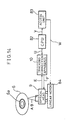
- the following description will discuss a method for moving the optical head 9, referring to Figure 14.
- the optical head 9 is moved by the tracking correction apparatus 10, a CPU 82, an access unit 83, and a linear motor 84.
- An access signal V is sent from the CPU 82 to the accessing unit 83.
- a driving signal W is sent from the accessing unit 83 to the linear motor 84 in response to the access signal V, thereby causing the optical head 9 to move so that the light beam A from the optical head 9 is projected on the tracking correction region 6a on the optical disk 6. Note that the optical head 9 moves in the radial direction of the optical disk 6.
- a correcting command signal U is supplied by the CPU 82 to the tracking correction apparatus 10, thereby causing to perform a correcting operation for the optical head 9.
- the light beam A from the optical head 9 is converged on the optical disk 6, and is reflected by the optical disk 6, thereby becoming the reflected light B, which is received by a detector provided with the light head 9.
- a tracking error signal E is detected, and is sent to the tracking correction apparatus 10.
- the tracking error signal E being corrected, becomes a corrected tracking error signal F.
- the corrected tracking error signal F thus corrected by the tracking correction apparatus 10 is fed back to the optical head 9, thereby causing the tracking operation to be carried out.
- a tracking correction apparatus 20 which has an adder 25 (signal detecting means) in addition to the arrangement of the tracking correction apparatus 10 (see Figure 5) may be substituted for the tracking correction apparatus 10.
- the detection signal C from the two-division photodetector 7 is sent to one of the input terminals of the adder 25, while the detection signal D to the other input terminal.
- the output of the adder 25 is sent to the A/D converter 12, i.e., the AID converter 12 and the adder 11 are not connected with each other.
- the detection signals C and D of the two-division photodetector 7 are respectively sent to the differential amplifier 8, where the tracking error signal E is generated.
- the tracking error signal E is sent to the adder 11 for the tracking correction operation.
- the detection signals C and D are also sent to the adder 25 for addition, and the added result is outputted as a total signal L.
- the wobble signal contained in the total signal L is converted into a digital signal M by the AID converter 12 in synchronization with the timing clock K. Then, as in the operation conducted by the tracking correction apparatus 10, the wobble signals E 1 and E 2 in the respective first and the second regions X and Y are compared by the CPU 13.
- a correction signal H according to the difference or the ratio thus found in the comparing operation is sent to the D/A converter 14 which outputs the correction signal I to the adder 11.
- the adder 11 adds the tracking error signal E and the correction signal I to obtain the corrected tracking error signal F.
- a tracking correction apparatus 30 may be substituted for the tracking correction apparatus 10.
- the tracking correction apparatus 30 has an envelope detector 35 in the place of the comparator 15 and the PLL circuit 16 (see Figure 6). More specifically, the output terminal of the adder 11 is connected to the input terminal of the envelope detector 35, and the output terminal of the envelope detector 35 is connected to the input terminal of the A/D converter 12.
- the envelope detector 35 is for detecting envelopes which are curves linking the peaks of the waveform of the wobble signal.
- the detector 35 detects amplitude, i.e. a difference between a peak value and a bottom value of the waveform.
- the detection signals C and D from the two-division photodetector 7 are sent to the differential amplifier 8, where a tracking error signal E is generated.
- the tracking error signal E is sent to the adder 11, for a tracking correction operation.
- the output of the adder 11 is sent to the envelope detector 35, which detects the amplitude of the wobble signal contained in the tracking error signal E and outputs the detected amplitude as an amplitude detection signal N.
- the amplitude detection signal N is converted by the A/D converter 12 into a digital signal G. Then, as in the operation conducted by the tracking correction apparatus 10, the wabble signals E 1 and E 2 in the respective first and second regions X and Y are compared by the CPU 13.
- a correction value H according to the difference or the ratio thus found in the comparing operation is sent to the D/A converter 14 which outputs the correction signal I to the adder 11.
- the adder 11 adds the tracking error signal E and the correction signal I, to obtain the corrected tracking error signal F with which the tracking correction operation is conducted.
- the amplitude detection signal N is obtained by the envelope detector 35, the timing clock K synchronizing with the wabble signal is not required. Accordingly, the structure is simplified in comparison with the tracking correction apparatus 10.
- a tracking correction apparatus 40 may be substituted for the tracking correction apparatus 20.
- the tracking correction apparatus 40 as shown in Figure 7, has such an arrangement in which the comparator 15 and the PLL circuit 16 are omitted and an envelope detector 35 is connected between the adder 25 and the A/D converter 12. Specifically, the output terminal of the adder 25 is connected to the input terminal of the envelope detector 35, while the output terminal of the envelope detector 35 is connected to the input terminal of the A/D converter 12.
- the detection signals C and D are sent to the adder 25 for addition, and the added result is outputted as a total signal L.
- Amplitude of the wabble signal contained in the total signal L is detected by the envelope detector 35, and a detected amplitude detection signal P is converted into a digital signal M by the A/D converter 12.
- the wobble signals E 1 and E 2 in the respective first and the second regions X and Y are compared by the CPU 13.
- a correction value H according to the difference or the ratio thus found in the comparing operation is sent to the D/A converter 14 which outputs the correction signal I to the adder 11.
- the adder 11 adds the tracking error signal E and the correction signal I, to obtain the corrected tracking error signal F with which the tracking correction operation is conducted.
- the tracking correction apparatuses 10, 20, 30, and 40 respectively adopt a digital arithmetic unit such as the CPU 13, it is possible to automatically correct a tracking operation even when the tracking operation is affected by the exchange of optical information recording media or a change in ambient temperature.
- the tracking correction apparatus 50 is composed of an adder 11, an envelope detector 35, two sample/hold (S/H) circuits 52 and 53, and a subtracter 54.
- an output terminal of the adder 11 is connected to the input terminal of the envelope detector 35, while the output terminal of the envelope detector 35 is connected to the input terminal of the S/H circuits 52 and 53 respectively.
- the output terminal of the S/H circuit 52 is connected with a positive input terminal of the subtracter 54, while the output terminal of the S/H circuit 53 is connected with a negative input terminal of the subtracter 54.
- An output terminal of the subtracter 54 is connected with one of the input terminals of the adder 11.
- the envelope detector 35 detects an amplitude detection signal N in response to the adder 11, and the amplitude detection signal N is sent to the S/H circuits 52 and 53 respectively.
- the S/H circuit 52 holds a wabble signal amplitude Q 1 derived from the first region X in accordance with a timing signal R 1
- the S/H circuit 53 holds a wabble signal amplitude Q 2 derived from the second region Y in accordance with a timing signal R 2 .
- the wobble signal amplitude Q 1 and Q 2 thus held are simultaneously sent to the subtracter 54, where a correction signal I is generated in accordance with the subtracting result.
- the correction signal I is added to the tracking error signal E in the adder 11.
- the tracking correction apparatus 50 may be arranged so that the wobble signal contained in the total signal is used, whereas the above arrangement employs the wobble signal contained in the tracking error signal.
- the "push-pull" amplification method is adopted as a tracking method according to the foregoing tracking correction apparatus, other method such as a three-spots method may be employed. Since it is possible to obtain a wobble signal when adopting the three-spots method, a tracking correction operation can be conducted in the same manner as that mentioned above.
- the total signal is an addition of output signals from a servo-use division-type light-receiving element (the two-division photodetector in the present embodiment), but an output signal from a light-receiving element for an RF signal-use (a reproducing data signal) may be substituted for the total signal, as being substantially the same as the total signal.
- FIG. 9 illustrates an example in which adopted is a tracking correction apparatus 60 which has the same structure as that of the tracking correction apparatus 20.
- the magneto-optical recording-reproducing apparatus is provided with photodetectors 62 and 63 for reproducing data signals, as well as a two-division photodetector 7 for a tracking servo-use.
- the light B reflected from the magneto-optical recording medium is divided by optical means such as a beam splitter (not shown) into two, that is, reflected light B 1 which is directed to the two-division photodetector 7 and a reflected light which is directed to a polarizing beam splitter 61.
- the reflected light directed to the polarizing beam splitter 61 is further divided into two polarized light components B 2 and B 3 in two polarization directions respectively.
- the components B 2 and B 3 are directed to the photodetectors 62 and 63 respectively.
- the polarized light component B 2 is converted into a reproduction signal T 2 by the photodetector 62, while the polarized light component B 3 is converted into a reproduction signal T 3 by the photodetector 63.
- the reproduction signals T 2 and T 3 are added by the adder 25, thereby obtaining an addition signal T.
- the addition signal T which is equivalent to the total signal L, is sent to the A/D converter 12.
- the following process is the same as that of the tracking correction apparatus 20. Namely, the correction signal I is added to the tracking error signal E, so that the tracking correcting operation is carried out.
- an optical disk employed in the present embodiment has a tracking correction region which doesn't share any part with a data recording region.
- a side wall of a groove is wobbled so that address information is obtained like the case of Figure 1.
- the data recording region is used as the second region Y, while the tracking correction region as the first region X. Note that it is possible that the first region X is used as the data recording region while the second region Y as the tracking correction region.
- amplitude of the wobble signal derived from the first region X is detected in the tracking correction region, and next, an amplitude of the wabble signal derived from the second region Y is detected in the data recording region. If the difference or ratio between the detected amplitudes indicate that the respective detected amplitudes are substantially equal, the tracking correction ends, whereas if not equal, the tracking correcting operation is repeated after jumping onto the tracking correction region.
- the correcting operation is quickened, since unnecessary moving actions of the light beam are omitted, thereby causing reduction in the time required for the tracking correction.
- the second region (or the first region) is also utilized as the data recording region, the capacity of an optical disk is made an effective use of.
- an optical disk employed in the present embodiment has a data recording region and a tracking correction region.
- the tracking correction region is composed of two tracks, assuming that one track is defined as the track which corresponds to one rotation of the optical disk.
- the first and the second regions X and Y are alternately provided as shown in Figure 15(a).
- FIG. 15(b) illustrates, another arrangement may be adopted, wherein the first region X, the second region Y, and the data recording region Z are repeatedly provided in this order in one track, without a specific tracking correction region.
- Figure 15 shows that the first track starts at around the left end of the line and ends at around a midpoint, and a second track starts at around the mid-point and ends at the right end.
- the tracking correcting operation starts (S11).
- the step S12 is not required, because every track has the first and the second regions X and Y in accordance with the above optical disk.
- the following process is the same as that of the first embodiment.
- An amplitude V 1 of the wobble signal E 1 contained in the tracking error signal E is detected (S13).
- the amplitude V 2 of the wobble signal E 2 contained in the tracking error signal E are detected (S14).
- Comparison between the amplitude V 1 and V 2 of the respective wabble signals is carried out to judge whether they are substantially equal or not (S15).
- the correcting operation is repeated in this way until amplitude of the wabble signals in the respective first and second regions X and Y are substantially equal, thereby leading the tracking position of the light beam onto the track center.
- first region X and the second region Y are alternately provided, only rotation of the optical disk, without a move of the light head, is required so as to repeat the correcting operation. Accordingly, it is possible to conduct a precise tracking correction operation within a short time.
Landscapes
- Optical Recording Or Reproduction (AREA)
- Optical Record Carriers And Manufacture Thereof (AREA)
Claims (21)
- Verfahren zum Ausführen einer Spurregelungskorrektur in solcher Weise, dass ein auf eine Spur auf einem optischen Aufzeichnungsträger (6) projizierter Lichtstrahl (A) nicht vom Zentrum der Spur abweicht,dadurch gekennzeichnet, dass auf dem Aufzeichnungsträger (6) mindestens ein kontinuierlicher Vorabgraben (1) vorhanden ist und im ersten Bereich (X) nur eine erste Seitenwand (1a) dieses kontinuierlichen Vorabgrabens mit einem analogen Wobbelsignal gewobbelt ist, und im zweiten Bereich (Y) nur die andere, entgegengesetzte Seitenwand (1b) dieses kontinuierlichen Vorabgrabens (1) mit einem analogen Wobbelsignal gewobbelt ist.wobei die Spur einen ersten und einen zweiten Bereich (X und Y) aufweist, wobei der erste Bereich (X) über einen Graben (1) verfügt, der in einer ersten radialen Richtung des Aufzeichnungsträgers (6) mit einer nicht in ein Spurregelungs-Frequenzband fallenden Frequenz gewobbelt ist, und der zweite Bereich (Y) über einen Graben (1) verfügt, die in einer zweiten radialen Richtung, entgegengesetzt zur ersten radialen Richtung des Aufzeichnungsträgers (6) mit einer nicht in das Spurregelungs-Frequenzband fallenden Frequenz gewobbelt ist;wobei eine erste Amplitude (E1) eines Wobbelsignals gemäß der Spurregelung des Lichtstrahls (A) in Bezug auf den ersten Bereich (X) erhalten wird;wobei eine zweite Amplitude (E2) eines Wobbelsignals gemäß der Spurregelung des Lichtstrahls (A) in Bezug auf den ersten Bereich (Y) erhalten wird und das Spurabweichungssignal entsprechend einem Vergleich der ersten und zweiten Amplitude (E1, E2) so korrigiert wird, dass die zwei Amplituden im Wesentlichen gleich werden;
- Spurregelungs-Korrekturverfahren nach Anspruch 1, bei dem der optische Aufzeichnungsträger (6) über einen Datenaufzeichnungsbereich (6b) und einen Spurregelungs-Korrekturbereich (6a) verfügt, wobei der Datenaufzeichnungsbereich (6b) über Aufzeichnungsspuren verfügt, in denen Daten aufgezeichnet werden, und der Spurregelungs-Korrekturbereich (6a) über andere Spuren als die Aufzeichnungsspuren verfügt, wobei der erste und der zweite Bereich (X, Y) im Spurregelungs-Korrekturbereich vorhanden sind, wobei das Verfahren ferner den folgenden Schritt aufweist:Verstellen des Lichtstrahls (A) in den Spurregelungs-Korrekturbereich (6a), bevor der Lichtstrahl (A) auf den Datenaufzeichnungsbereich (6b) gestrahlt wird.
- Spurregelungs-Korrekturverfahren nach Anspruch 1, dadurch gekennzeichnet, dass der zweite Bereich (Y) ein Datenaufzeichnungsbereich mit Aufzeichnungsspuren ist, in denen Daten aufgezeichnet werden, und der erste Bereich ein Spurregelungs-Korrekturbereich mit anderen Spuren als den Aufzeichnungsspuren ist, ferner mit dem folgenden Schritt:Verstellen des Lichtstrahls auf den Spurregelungs-Korrekturbereich bevor der Lichtstrahl (A) auf den Datenaufzeichnungsbereich gestrahlt wird.
- Vorrichtung zum Ausführen einer Spurregelungskorrektur in solcher Weise, dass ein auf eine Spur eines optischen Aufzeichnungsträgers (6) gestrahlter Lichtstrahl (A) nicht vom Zentrum der Spur abweicht, wobei die Spur über einen ersten und einen zweiten Bereich (X, Y) verfügt, wobei der erste Bereich (X) einen Graben (1) aufweist, der in einer ersten radialen Richtung des Aufzeichnungsträgers (6) mit einer nicht in ein Spurregelungs-Frequenzband fallenden Frequenz gewobbelt ist, und der zweite Bereich (Y) einen Graben (1) aufweist, der in einer zweiten radialen Richtung, entgegengesetzt zur ersten radialen Richtung, des Aufzeichnungsträgers (6);
dadurch gekennzeichnet, dassder Graben über mindestens einen kontinuierlichen Vorabgraben (1) auf dem Aufzeichnungsträger (6) verfügt und im ersten Bereich (X) nur eine erste Seitenwand (1a) dieses kontinuierlichen Vorabgrabens mit einem analogen Wobbelsignal gewobbelt ist und im zweiten Bereich (Y) nur die andere, entgegengesetzte Seitenwand (1b) dieses kontinuierlichen Vorabgrabens (1) mit einem analogen Wobbelsignal gewobbelt ist, und die Vorrichtung Folgendes aufweist:eine Signalerfassungseinrichtung (7, 8) zum Ausgeben eines Spurabweichungssignals (E, F) während einer Spurregelung des Lichtstrahls (A) in Bezug auf den optischen Aufzeichnungsträger (6);eine Amplitudenerfassungseinrichtung (11, 12, 16) zum Erfassen der Amplitude eines Wobbelsignals im Spurabweichungssignal;eine Vergleichseinrichtung (13) zum Vergleichen einer ersten Amplitude des vom ersten Bereich hergeleiteten Wobbelsignals und einer zweiten Amplitude des vom zweiten Bereich hergeleiteten Wobbelsignals; undeine Korrektureinrichtung (10; 14) zum Korrigieren des Spurabweichungssignals (E, F) auf die Vergleichseinrichtung (13) hin in solcher Weise, dass die erste und zweite Amplitude im Wesentlichen gleich sind. - Spurregelungs-Korrekturvorrichtung nach Anspruch 4, bei der die Korrektureinrichtung (10; 14) eine Addiereinrichtung (11) zum Addieren des Spurabweichungssignals (E) und eines Korrektursignals (I) aufweist, das auf Grundlage des Ausgangssignals der Vergleichseinrichtung (13) erzeugt wurde.
- Spurregelungs-Korrekturvorrichtung nach Anspruch 4, bei derdie Amplitudenerfassungseinrichtung (11, 12, 16) die Amplitude in digitaler Form ausgibt unddie Vergleichseinrichtung (13) eine digitale Verarbeitungseinrichtung zum digitalen Vergleichen der Amplituden aufweist.
- Spurregelungs-Korrekturvorrichtung nach Anspruch 4, bei der die Amplitudenerfassungseinrichtung Folgendes aufweist:eine Taktsignal-Erzeugungseinrichtung (16) zum Erzeugen eines Timingtaktsignals (K), das mit jeweiligen Peaks und Tälern des Wobbelsignals, das ein analoges Signal ist, synchronisiert ist; undeine Umsetzeinrichtung (12) zum Erkennen jedes Peaks und jedes Tals des Wobbelsignals synchron mit dem Timingtaktsignal (K) und zum Umsetzen der Differenz zwischen dem erfassten Peak und dem erfassten Tal in ein digitales Signal.
- Spurregelungs-Korrekturvorrichtung nach Anspruch 4, bei der die Amplitudenerfassungseinrichtung eine Einhüllendenerfassungseinrichtung (35) zum Erfassen der Einhüllenden aufweist, die durch Verbinden von Peaks des Signalverlaufs des Wobbelsignals aufgefunden wird, um die Amplitude des Wobbelsignals zu erfassen.
- Spurregelungs-Korrekturvorrichtung nach Anspruch 4, bei derdie Amplitudenerfassungseinrichtung Folgendes aufweist: (1) eine Einhüllendenerfassungseinrichtung (35) zum Erfassen einer Einhüllenden, die durch Verbinden von Peaks des Signalverlaufs des Wobbelsignals aufgefunden wird, um die Amplitude desselben zu erfassen, (2) eine erste Abtast-Halte-Einrichtung (52) zum Speichern der ersten Amplitude (Q1) des vom ersten Bereich (X) hergeleiteten Wobbelsignals für eine vorbestimmte Periode, und (3) eine zweite Abtast/Halte-Einrichtung (53) zum Speichern der zweiten Amplitude (Q2) des vom zweiten Bereich (Y) hergeleiteten Wobbelsignals für eine vorbestimmte Periode; unddie Vergleichseinrichtung eine Subtrahiereinrichtung (54) zum Ausführen einer Subtraktion zwischen der ersten Amplitude (Q1) und der zweiten Amplitude (Q2) aufweist, wobei die erste und die zweite Amplitude gleichzeitig eingegeben werden.
- Vorrichtung zum Ausführen einer Spurregelungskorrektur in solcher Weise, dass ein auf eine Spur eines optischen Aufzeichnungsträgers (6) gestrahlter Lichtstrahl (A) nicht vom Zentrum der Spur abweicht,dadurch gekennzeichnet, dasswobei die Spur über einen ersten und einen zweiten Bereich (X, Y) verfügt, wobei der erste Bereich (X) einen Graben (1) aufweist, der in einer ersten radialen Richtung des Aufzeichnungsträgers (6) mit einer nicht in ein Spurregelungs-Frequenzband fallenden Frequenz gewobbelt ist, und der zweite Bereich (Y) einen Graben (1) aufweist, der in einer zweiten radialen Richtung, entgegengesetzt zur ersten radialen Richtung, des Aufzeichnungsträgers (6);auf dem Aufzeichnungsträger (6) mindestens ein kontinuierlicher Vorabgraben (1) vorhanden ist und im ersten Bereich (X) nur eine erste Seitenwand (1a) dieses kontinuierlichen Vorabgrabens mit einem analogen Wobbelsignal gewobbelt ist und im zweiten Bereich (Y) nur die andere, entgegengesetzte Seitenwand (1b) dieses kontinuierlichen Vorabgrabens (1) mit einem analogen Wobbelsignal gewobbelt ist, und die Vorrichtung Folgendes aufweist:eine erste Signalerfassungseinrichtung (7, 8) zum Ausgeben eines Spurabweichungssignals (E, F) während einer Spurregelung des Lichtstrahls (A) in Bezug auf den optischen Aufzeichnungsträger (6);eine zweite Signalerfassungseinrichtung mit einer Addiereinrichtung (25) zum Addieren der empfangenen Lichtmengen des reflektierten Lichtstrahls (B) und zum Umsetzen der Lichtmenge in ein elektrisches Signal, das als Gesamtsignal (T) ausgegeben wird;eine Amplitudenerfassungseinrichtung (11, 12, 16) zum Erfassen der Amplitude eines Wobbelsignals im Gesamtsignal (T);eine Vergleichseinrichtung (13) zum Vergleichen einer ersten Amplitude des vom ersten Bereich hergeleiteten Wobbelsignals und einer zweiten Amplitude des vom zweiten Bereich hergeleiteten Wobbelsignals; undeine Korrektureinrichtung (14) zum Korrigieren des Spurabweichungssignals auf die Vergleichseinrichtung hin in solcher Weise, dass die erste und zweite Amplitude im Wesentlichen gleich sind.
- Spurregelungs-Korrekturvorrichtung nach Anspruch 10, bei der die Korrektureinrichtung (10; 14) eine zweite Addiereinrichtung (11) zum Addieren des Spurabweichungssignals (E) und eines Korrektursignals (I) aufweist, das auf Grundlage des Ausgangssignals (H) der Vergleichseinrichtung (13) erzeugt wurde.
- Spurregelungs-Korrekturvorrichtung nach Anspruch 10, bei derdie Amplitudenerfassungseinrichtung (12, 16) die Amplitude in digitaler Form ausgibt unddie Vergleichseinrichtung (13) eine digitale Verarbeitungseinrichtung zum digitalen Vergleichen der Amplituden aufweist.
- Spurregelungs-Korrekturvorrichtung nach Anspruch 10, bei der die Amplitudenerfassungseinrichtung Folgendes aufweist:eine Taktsignal-Erzeugungseinrichtung (16) zum Erzeugen eines Timingtaktsignals, das mit jeweiligen Peaks und Tälern des Wobbelsignals synchronisiert ist; undeine Umsetzeinrichtung (12) zum Erkennen jedes Peaks und jedes Tals des Wobbelsignals synchron mit dem Timingtaktsignal und zum Umsetzen der Differenz zwischen dem erfassten Peak und dem erfassten Tal in ein digitales Signal.
- Spurregelungs-Korrekturvorrichtung nach Anspruch 10, bei der die Amplitudenerfassungseinrichtung eine Einhüllendenerfassungseinrichtung (35) zum Erfassen der Einhüllenden aufweist, die durch Verbinden von Peaks des Signalverlaufs des Wobbelsignals aufgefunden wird, um die Amplitude des Wobbelsignals zu erfassen.
- Spurregelungs-Korrekturvorrichtung nach Anspruch 10, bei derdie Amplitudenerfassungseinrichtung Folgendes aufweist: (1) eine Einhüllendenerfassungseinrichtung (35) zum Erfassen einer Einhüllenden, die durch Verbinden von Peaks des Signalverlaufs des Wobbelsignals aufgefunden wird, um die Amplitude desselben zu erfassen, (2) eine erste Abtast-Halte-Einrichtung (52) zum Speichern der ersten Amplitude (Q1) des vom ersten Bereich (X) hergeleiteten Wobbelsignals für eine vorbestimmte Periode, und (3) eine zweite Abtast/Halte-Einrichtung (53) zum Speichern der zweiten Amplitude (Q2) des vom zweiten Bereich (Y) hergeleiteten Wobbelsignals für eine vorbestimmte Periode; unddie Vergleichseinrichtung einer Subtrahiereinrichtung (54) zum Ausführen einer Subtraktion zwischen der ersten Amplitude (Q1) und der zweiten Amplitude (Q2) aufweist, wobei die erste und die zweite Amplitude gleichzeitig eingegeben werden.
- Optische Platte mit einer Spur mit einem ersten und einem zweiten Bereich (X, Y), wobei der erste Bereich (X) einen Graben (1) aufweist, der in einer ersten radialen Richtung der optischen Platte mit einer nicht in ein Spurregelungs-Frequenzband fallenden Frequenz gewobbelt ist, und der zweite Bereich (Y) einen Graben (1) aufweist, der in einer zweiten radialen Richtung der optischen Platte mit einer nicht in das Spurregelungs-Frequenzband fallenden Frequenz gewobbelt ist;
dadurch gekennzeichnet, dass die optische Platte mit mindestens einem kontinuierlichen Vorabgraben (1) versehen ist und im ersten Bereich (X) nur eine erste Seitenwand (1a) dieses kontinuierlichen Vorabgrabens (1) mit einem analogen Wobbelsignal gewobbelt ist und im zweiten Bereich (Y) nur die andere, entgegengesetzte Seitenwand (1b) dieses kontinuierlichen Vorabgrabens (1) mit einem analogen Wobbelsignal gewobbelt ist. - Optische Platte nach Anspruch 16, ferner mit einem Datenaufzeichnungsbereich (6b) und einem Spurregelungs-Korrektur-Bereich (6a), wobei der Datenaufzeichnungsbereich (6b) Aufzeichnungsspuren aufweist, auf denen Daten aufgezeichnet werden, und der Spurregelungs-Korrekturbereich andere Spuren als die Aufzeichnungsspuren aufweist, wobei der erste und der zweite Bereich (X, Y) im Spurregelungs-Korrekturbereich (6a) vorhanden sind.
- Optische Platte nach Anspruch 17, bei der der Spurregelungs-Korrekturbereich aus zwei Spuren besteht, von denen die eine den ersten Bereich (X) und die andere den zweiten Bereich (Y) bildet, wobei eine Spur als solche Spur definiert ist, die einer Umdrehung der optischen Platte entspricht.
- Optische Platte nach Anspruch 17, bei der der erste und der zweite Bereich (X, Y) abwechselnd innerhalb einer Spur im Spurregelungs-Korrekturbereich vorhanden sind, wobei eine Spur als solche Spur definiert ist, die einer Umdrehung der optischen Platte entspricht.
- Optische Platte nach Anspruch 16, bei der der zweite Bereich (Y) ein Datenaufzeichnungsbereich mit Aufzeichnungsspuren ist, in denen Daten aufgezeichnet sind, und der erste Bereich (X) ein Spurregelungs-Korrekturbereich mit anderen Spuren als den Aufzeichnungsspuren ist.
- Optische Platte nach Anspruch 16, bei der ein Datenaufzeichnungsbereich zum Aufzeichnen von Daten, der erste Bereich und der zweite Bereich innerhalb einer Spur in dieser Reihenfolge wiederholt vorhanden sind, wobei eine Spur als solche Spur definiert ist, die einer Umdrehung der optischen Platte entspricht.
Applications Claiming Priority (3)
| Application Number | Priority Date | Filing Date | Title |
|---|---|---|---|
| JP13224495 | 1995-05-30 | ||
| JP7132244A JPH08329507A (ja) | 1995-05-30 | 1995-05-30 | トラッキング補正方法及びその装置並びに光ディスク |
| JP132244/95 | 1995-05-30 |
Publications (3)
| Publication Number | Publication Date |
|---|---|
| EP0745976A2 EP0745976A2 (de) | 1996-12-04 |
| EP0745976A3 EP0745976A3 (de) | 1998-02-11 |
| EP0745976B1 true EP0745976B1 (de) | 2003-06-25 |
Family
ID=15076744
Family Applications (1)
| Application Number | Title | Priority Date | Filing Date |
|---|---|---|---|
| EP96106684A Expired - Lifetime EP0745976B1 (de) | 1995-05-30 | 1996-04-26 | Verfahren und Vorrichtung zur Trackingkorrektur und optische Platte dafür |
Country Status (4)
| Country | Link |
|---|---|
| US (1) | US5715217A (de) |
| EP (1) | EP0745976B1 (de) |
| JP (1) | JPH08329507A (de) |
| DE (1) | DE69628788T2 (de) |
Families Citing this family (21)
| Publication number | Priority date | Publication date | Assignee | Title |
|---|---|---|---|---|
| US6058099A (en) | 1995-12-29 | 2000-05-02 | Sony Corporation | Disc-shaped information recording medium having offset address information data |
| US5875157A (en) * | 1996-03-18 | 1999-02-23 | Sony Corporation | Tracking error detecting circuit in disc-shaped recording medium reproducing and recording apparatus |
| DE69735978T2 (de) * | 1996-06-14 | 2007-02-01 | Mitsubishi Kagaku Media Co., Ltd. | Optische Phasenänderungsscheibe |
| KR100246394B1 (ko) * | 1996-06-22 | 2000-03-15 | 구자홍 | 정보기록/재생장치 및 방법 |
| JPH1074321A (ja) * | 1996-07-05 | 1998-03-17 | Sharp Corp | 光ディスク基板及びその製造方法並びに光ディスク及びその再生方法 |
| DE69729606T2 (de) * | 1996-07-09 | 2005-07-07 | Sharp K.K. | Optische Platte mit verteilten Wobbelsektionen, Herstellungsverfahren und Verfahren zur Aufzeichnung und Wiedergabe |
| KR20000064320A (ko) * | 1996-09-03 | 2000-11-06 | 요트.게.아. 롤페즈 | 정보 블록의 기록 및 판독용 정보매체, 판독/기록장치와 판독장치 |
| KR100324883B1 (ko) | 1996-09-26 | 2002-02-28 | 다카노 야스아키 | 기록 매체 및 그 재생 장치 |
| IN192585B (de) | 1996-10-25 | 2004-05-08 | Matsushita Electric Industrial Co Ltd | |
| JP3224513B2 (ja) * | 1996-11-27 | 2001-10-29 | シャープ株式会社 | 光ディスクの再生方法 |
| JP3512583B2 (ja) * | 1997-01-30 | 2004-03-29 | シャープ株式会社 | 光ディスク |
| JPH10283689A (ja) * | 1997-02-07 | 1998-10-23 | Sanyo Electric Co Ltd | 情報記録再生装置 |
| AU4725797A (en) * | 1997-05-28 | 1998-12-30 | Sanyo Electric Co., Ltd. | Recording medium and reproducing apparatus therefor |
| JPH1116216A (ja) * | 1997-06-19 | 1999-01-22 | Sony Corp | 光ディスク及び光ディスク装置 |
| US6262955B1 (en) * | 1997-08-30 | 2001-07-17 | Lg Electronics Inc. | Tracking control method and apparatus and recording medium adaptive to the same |
| US6104682A (en) * | 1998-07-23 | 2000-08-15 | Matsushita Electric Industrial Co., Ltd. | Disk apparatus having a data reproducing system using a digital PLL |
| KR100527402B1 (ko) * | 2000-05-31 | 2005-11-15 | 주식회사 하이닉스반도체 | 디디알 동기식메모리의 지연고정루프 장치 |
| MXPA03001650A (es) | 2000-09-01 | 2003-06-24 | Matsushita Electric Industrial Co Ltd | Medio de disco optico, reproductor y grabador de disco optico. |
| GB0029121D0 (en) * | 2000-11-29 | 2001-01-10 | Lsi Logic Europ Ltd | Apparatus and method providing a mirror averaging function to generate a mirror signal from optical data on an optical disc |
| JP4201158B2 (ja) * | 2001-10-19 | 2008-12-24 | コーニンクレッカ フィリップス エレクトロニクス エヌ ヴィ | 光ディスク媒体、情報記録方法、及び情報記録装置 |
| JP4285727B2 (ja) * | 2002-11-08 | 2009-06-24 | 株式会社フロンティア | ブロー成形装置の移送機構 |
Citations (1)
| Publication number | Priority date | Publication date | Assignee | Title |
|---|---|---|---|---|
| US4866688A (en) * | 1985-12-20 | 1989-09-12 | Hitachi, Ltd. | Composite tracking servo system for optical disc apparatus with track offset correction |
Family Cites Families (7)
| Publication number | Priority date | Publication date | Assignee | Title |
|---|---|---|---|---|
| US4716560A (en) * | 1984-05-22 | 1987-12-29 | Victor Company Of Japan, Ltd. | Recording disc and method for fabricating same |
| US5185732A (en) * | 1988-06-20 | 1993-02-09 | Sony Corporation | Recording medium and recording and reproducing apparatus employing the recording medium |
| JP3021029B2 (ja) * | 1990-11-20 | 2000-03-15 | シャープ株式会社 | 光磁気記録媒体の情報アクセス方法 |
| KR950010418B1 (ko) * | 1991-08-28 | 1995-09-16 | 미쯔비시덴끼 가부시끼가이샤 | 광기록재생장치 |
| JP2854187B2 (ja) * | 1992-05-12 | 1999-02-03 | シャープ株式会社 | 光記録媒体及び情報記録再生装置 |
| EP0793220B1 (de) * | 1992-07-31 | 2001-05-16 | Matsushita Electric Industrial Co., Ltd. | Vorrichtung zur optischen Aufzeichnung/Wiedergabe von Daten |
| JPH06290462A (ja) * | 1993-04-05 | 1994-10-18 | Sony Corp | 信号検出方法及び信号検出装置 |
-
1995
- 1995-05-30 JP JP7132244A patent/JPH08329507A/ja active Pending
-
1996
- 1996-04-25 US US08/637,545 patent/US5715217A/en not_active Expired - Lifetime
- 1996-04-26 EP EP96106684A patent/EP0745976B1/de not_active Expired - Lifetime
- 1996-04-26 DE DE69628788T patent/DE69628788T2/de not_active Expired - Lifetime
Patent Citations (1)
| Publication number | Priority date | Publication date | Assignee | Title |
|---|---|---|---|---|
| US4866688A (en) * | 1985-12-20 | 1989-09-12 | Hitachi, Ltd. | Composite tracking servo system for optical disc apparatus with track offset correction |
Also Published As
| Publication number | Publication date |
|---|---|
| JPH08329507A (ja) | 1996-12-13 |
| US5715217A (en) | 1998-02-03 |
| DE69628788D1 (de) | 2003-07-31 |
| EP0745976A2 (de) | 1996-12-04 |
| EP0745976A3 (de) | 1998-02-11 |
| DE69628788T2 (de) | 2004-05-19 |
Similar Documents
| Publication | Publication Date | Title |
|---|---|---|
| EP0745976B1 (de) | Verfahren und Vorrichtung zur Trackingkorrektur und optische Platte dafür | |
| KR100202437B1 (ko) | 광디스크구동장치 및 광디스크 | |
| KR100187795B1 (ko) | 포커스 밸런스 자동조정장치 및 자동조정방법 | |
| KR910003459B1 (ko) | 트래킹 에러 신호중의 오프셋트를 감소시킨 광학 디스크 기록 재생장치 | |
| EP0422227B1 (de) | Optische plattenspeicher-wiedergabeanordnung | |
| JPH0620287A (ja) | 光ディスク記録システム及びライト/リード機構の位置決めのための方法 | |
| KR100246968B1 (ko) | 광디스크에 기록된 정보재생장치 및 방법 | |
| US6175540B1 (en) | Tracking control method and apparatus | |
| US6418104B1 (en) | Tilt detector | |
| US7057994B2 (en) | Apparatus and method for reproducing information from two types of optical disks having discrimination marks formed along tracks thereof | |
| US6347067B1 (en) | Apparatus and method for adjusting a reference voltage to detect a Traverse signal based on the types of optical medium | |
| KR100489545B1 (ko) | 광 디스크장치 | |
| JPH11161958A (ja) | 信号補完装置、情報再生装置及び情報記録装置 | |
| US20030169649A1 (en) | Disk drive apparatus and information reading method | |
| US6522605B1 (en) | Disk apparatus for focusing and adjusting a laser beam | |
| US6208604B1 (en) | Apparatus and method for optical disk reproduction | |
| JPH07254156A (ja) | 光ディスク及び光ディスク再生装置の信号処理回路 | |
| KR100556495B1 (ko) | 광 디스크 기록 재생 방법 및 장치 | |
| US20020036966A1 (en) | Tracking control method and tracking control apparatus in which a tracking offset component is subtracted from a tracking error | |
| KR20000074745A (ko) | 광 기록 매체의 기록재생방법 | |
| KR100531358B1 (ko) | 광 기록재생장치의 트랙킹 서보 장치 | |
| JP2766149B2 (ja) | 光ディスクのトラッキング制御装置 | |
| KR100565717B1 (ko) | 광 기록 매체의 기록재생방법 및 그 장치 | |
| KR100587266B1 (ko) | 광 기록매체의 기록재생 방법 | |
| JPH10283730A (ja) | 光ディスク再生装置および方法 |
Legal Events
| Date | Code | Title | Description |
|---|---|---|---|
| PUAI | Public reference made under article 153(3) epc to a published international application that has entered the european phase |
Free format text: ORIGINAL CODE: 0009012 |
|
| AK | Designated contracting states |
Kind code of ref document: A2 Designated state(s): DE FR GB |
|
| PUAL | Search report despatched |
Free format text: ORIGINAL CODE: 0009013 |
|
| AK | Designated contracting states |
Kind code of ref document: A3 Designated state(s): DE FR GB |
|
| 17P | Request for examination filed |
Effective date: 19980303 |
|
| 17Q | First examination report despatched |
Effective date: 20000426 |
|
| GRAG | Despatch of communication of intention to grant |
Free format text: ORIGINAL CODE: EPIDOS AGRA |
|
| GRAG | Despatch of communication of intention to grant |
Free format text: ORIGINAL CODE: EPIDOS AGRA |
|
| GRAH | Despatch of communication of intention to grant a patent |
Free format text: ORIGINAL CODE: EPIDOS IGRA |
|
| GRAH | Despatch of communication of intention to grant a patent |
Free format text: ORIGINAL CODE: EPIDOS IGRA |
|
| GRAA | (expected) grant |
Free format text: ORIGINAL CODE: 0009210 |
|
| AK | Designated contracting states |
Designated state(s): DE FR GB |
|
| REG | Reference to a national code |
Ref country code: GB Ref legal event code: FG4D |
|
| REF | Corresponds to: |
Ref document number: 69628788 Country of ref document: DE Date of ref document: 20030731 Kind code of ref document: P |
|
| ET | Fr: translation filed | ||
| PLBE | No opposition filed within time limit |
Free format text: ORIGINAL CODE: 0009261 |
|
| STAA | Information on the status of an ep patent application or granted ep patent |
Free format text: STATUS: NO OPPOSITION FILED WITHIN TIME LIMIT |
|
| 26N | No opposition filed |
Effective date: 20040326 |
|
| PGFP | Annual fee paid to national office [announced via postgrant information from national office to epo] |
Ref country code: GB Payment date: 20140423 Year of fee payment: 19 |
|
| PGFP | Annual fee paid to national office [announced via postgrant information from national office to epo] |
Ref country code: DE Payment date: 20140430 Year of fee payment: 19 Ref country code: FR Payment date: 20140409 Year of fee payment: 19 |
|
| REG | Reference to a national code |
Ref country code: DE Ref legal event code: R119 Ref document number: 69628788 Country of ref document: DE |
|
| GBPC | Gb: european patent ceased through non-payment of renewal fee |
Effective date: 20150426 |
|
| PG25 | Lapsed in a contracting state [announced via postgrant information from national office to epo] |
Ref country code: DE Free format text: LAPSE BECAUSE OF NON-PAYMENT OF DUE FEES Effective date: 20151103 Ref country code: GB Free format text: LAPSE BECAUSE OF NON-PAYMENT OF DUE FEES Effective date: 20150426 |
|
| REG | Reference to a national code |
Ref country code: FR Ref legal event code: ST Effective date: 20151231 |
|
| PG25 | Lapsed in a contracting state [announced via postgrant information from national office to epo] |
Ref country code: FR Free format text: LAPSE BECAUSE OF NON-PAYMENT OF DUE FEES Effective date: 20150430 |