EP0746007A2 - Relais électromagnétique polarisé - Google Patents
Relais électromagnétique polarisé Download PDFInfo
- Publication number
- EP0746007A2 EP0746007A2 EP96108869A EP96108869A EP0746007A2 EP 0746007 A2 EP0746007 A2 EP 0746007A2 EP 96108869 A EP96108869 A EP 96108869A EP 96108869 A EP96108869 A EP 96108869A EP 0746007 A2 EP0746007 A2 EP 0746007A2
- Authority
- EP
- European Patent Office
- Prior art keywords
- base
- armature
- relay according
- base body
- coil
- Prior art date
- Legal status (The legal status is an assumption and is not a legal conclusion. Google has not performed a legal analysis and makes no representation as to the accuracy of the status listed.)
- Granted
Links
- 150000001875 compounds Chemical class 0.000 claims abstract description 9
- 238000004382 potting Methods 0.000 claims abstract description 8
- 239000011810 insulating material Substances 0.000 claims description 9
- 238000005192 partition Methods 0.000 claims description 7
- 230000005291 magnetic effect Effects 0.000 claims description 4
- 239000002184 metal Substances 0.000 claims description 4
- 238000009423 ventilation Methods 0.000 claims description 4
- 239000000969 carrier Substances 0.000 claims description 3
- 238000005266 casting Methods 0.000 claims description 3
- 238000007789 sealing Methods 0.000 claims description 3
- 239000004020 conductor Substances 0.000 claims 3
- 238000010276 construction Methods 0.000 abstract description 8
- 229910000679 solder Inorganic materials 0.000 abstract description 6
- 238000012986 modification Methods 0.000 description 7
- 230000004048 modification Effects 0.000 description 7
- 238000005516 engineering process Methods 0.000 description 3
- LVDRREOUMKACNJ-BKMJKUGQSA-N N-[(2R,3S)-2-(4-chlorophenyl)-1-(1,4-dimethyl-2-oxoquinolin-7-yl)-6-oxopiperidin-3-yl]-2-methylpropane-1-sulfonamide Chemical compound CC(C)CS(=O)(=O)N[C@H]1CCC(=O)N([C@@H]1c1ccc(Cl)cc1)c1ccc2c(C)cc(=O)n(C)c2c1 LVDRREOUMKACNJ-BKMJKUGQSA-N 0.000 description 2
- 239000000853 adhesive Substances 0.000 description 2
- 230000001070 adhesive effect Effects 0.000 description 2
- 238000005520 cutting process Methods 0.000 description 2
- 230000005294 ferromagnetic effect Effects 0.000 description 2
- 238000009413 insulation Methods 0.000 description 2
- 238000004519 manufacturing process Methods 0.000 description 2
- 238000005476 soldering Methods 0.000 description 2
- 238000004804 winding Methods 0.000 description 2
- QOVYHDHLFPKQQG-NDEPHWFRSA-N N[C@@H](CCC(=O)N1CCC(CC1)NC1=C2C=CC=CC2=NC(NCC2=CN(CCCNCCCNC3CCCCC3)N=N2)=N1)C(O)=O Chemical compound N[C@@H](CCC(=O)N1CCC(CC1)NC1=C2C=CC=CC2=NC(NCC2=CN(CCCNCCCNC3CCCCC3)N=N2)=N1)C(O)=O QOVYHDHLFPKQQG-NDEPHWFRSA-N 0.000 description 1
- 230000000712 assembly Effects 0.000 description 1
- 238000000429 assembly Methods 0.000 description 1
- 230000006735 deficit Effects 0.000 description 1
- 238000001125 extrusion Methods 0.000 description 1
- 238000009434 installation Methods 0.000 description 1
- 238000002372 labelling Methods 0.000 description 1
- 239000000463 material Substances 0.000 description 1
- 238000000034 method Methods 0.000 description 1
- 230000035515 penetration Effects 0.000 description 1
- 230000002093 peripheral effect Effects 0.000 description 1
- 230000005855 radiation Effects 0.000 description 1
- 230000000717 retained effect Effects 0.000 description 1
- 238000005096 rolling process Methods 0.000 description 1
- 239000007787 solid Substances 0.000 description 1
- 238000003860 storage Methods 0.000 description 1
Images






Classifications
-
- H—ELECTRICITY
- H01—ELECTRIC ELEMENTS
- H01H—ELECTRIC SWITCHES; RELAYS; SELECTORS; EMERGENCY PROTECTIVE DEVICES
- H01H51/00—Electromagnetic relays
- H01H51/22—Polarised relays
- H01H51/2272—Polarised relays comprising rockable armature, rocking movement around central axis parallel to the main plane of the armature
- H01H51/2281—Contacts rigidly combined with armature
- H01H51/229—Blade-spring contacts alongside armature
-
- H—ELECTRICITY
- H01—ELECTRIC ELEMENTS
- H01H—ELECTRIC SWITCHES; RELAYS; SELECTORS; EMERGENCY PROTECTIVE DEVICES
- H01H50/00—Details of electromagnetic relays
- H01H50/02—Bases; Casings; Covers
- H01H50/026—Details concerning isolation between driving and switching circuit
-
- H—ELECTRICITY
- H01—ELECTRIC ELEMENTS
- H01H—ELECTRIC SWITCHES; RELAYS; SELECTORS; EMERGENCY PROTECTIVE DEVICES
- H01H51/00—Electromagnetic relays
- H01H51/22—Polarised relays
-
- H—ELECTRICITY
- H01—ELECTRIC ELEMENTS
- H01H—ELECTRIC SWITCHES; RELAYS; SELECTORS; EMERGENCY PROTECTIVE DEVICES
- H01H11/00—Apparatus or processes specially adapted for the manufacture of electric switches
- H01H11/0006—Apparatus or processes specially adapted for the manufacture of electric switches for converting electric switches
- H01H11/0031—Apparatus or processes specially adapted for the manufacture of electric switches for converting electric switches for allowing different types or orientation of connections to contacts
-
- H—ELECTRICITY
- H01—ELECTRIC ELEMENTS
- H01H—ELECTRIC SWITCHES; RELAYS; SELECTORS; EMERGENCY PROTECTIVE DEVICES
- H01H1/00—Contacts
- H01H1/58—Electric connections to or between contacts; Terminals
- H01H2001/5888—Terminals of surface mounted devices [SMD]
-
- H—ELECTRICITY
- H01—ELECTRIC ELEMENTS
- H01H—ELECTRIC SWITCHES; RELAYS; SELECTORS; EMERGENCY PROTECTIVE DEVICES
- H01H50/00—Details of electromagnetic relays
- H01H50/02—Bases; Casings; Covers
- H01H50/023—Details concerning sealing, e.g. sealing casing with resin
-
- H—ELECTRICITY
- H01—ELECTRIC ELEMENTS
- H01H—ELECTRIC SWITCHES; RELAYS; SELECTORS; EMERGENCY PROTECTIVE DEVICES
- H01H50/00—Details of electromagnetic relays
- H01H50/14—Terminal arrangements
Definitions
- a relay of the type mentioned is described in WO 94/22156.
- a bobbin is placed directly on the base, which in addition to the coil winding and the core also carries the yokes and the permanent magnet and which is connected directly to the base in side areas.
- a cap placed over the bobbin is connected to the base to form a closed housing.
- This known structure is designed for conventional solder connection technology; for stronger mechanical or thermal loads, however, the connection structure of the base and the coil body is not designed.
- relays should, as far as possible, be able to withstand the mechanical and thermal loads occurring with these techniques without their construction the precisely set characteristic values of the relay deteriorate.
- the aim of the present invention is to construct a polarized relay of the type mentioned in such a way that on the one hand the insulation between the contacts and the coil is improved and on the other hand the construction is made more stable overall, so that the desired characteristics of the relay are set in a simpler manner and safer to maintain when handling or operating the relay.
- a basic construction is to be created which is suitable only for the installation of different connection elements both for solder pin connection and for SMT connection and for press-in connection.
- this aim is achieved in the aforementioned relay structure in that a base body made of insulating material is provided, which forms a partition parallel to the base plane - with bushings for the yokes - between the armature and the coil, that the base body has side walls with the base is nested and forms an at least partially closed switching space with it and that the base body has a shoulder on both sides of the armature, under which the contact pins arranged in a row are located and which is suitable as a support area for these pins if necessary.
- the base body provided according to the invention results in a high rigidity and stability of the relay structure.
- the adjustments made during production are thus reliably retained, even if mechanical or thermal loads act on the relay housing from the outside.
- the construction according to the invention is particularly effective when connecting pins are used which extend vertically upwards from the base to the respective support region of the base body.
- the connecting pins are fixed in each case in grooves in the base body and there by means of a hardenable sealing compound. So it is possible that after the assembly of the armature with a precise adjustment of the contact spacing of the base, the magnet system connected to the base body can be pushed onto the base until the armature lies exactly against the magnet system or has reached the specified air gaps to the yokes .
- the base body By pouring in adhesive or potting compound, on the one hand, the base body can then be sealingly connected to the base, the connecting pins being cast in the grooves mentioned in a preceding or simultaneous operation.
- This control room also has compared to similarly constructed Relay has a very low air volume because the coil space is not included. This is particularly advantageous in the case of strong heat, such as when soldering the relay, in particular when reflow soldering SMT connections.
- the base body thus forms closed side walls at least around the contact space, so that the housing cap which would otherwise be required can be dispensed with.
- An embodiment in which the base body has an H-shaped cross section and thus also accommodates the coil in an upwardly open, trough-shaped coil space is particularly advantageous.
- This coil space is expediently completely or at least partially filled with potting compound, which further increases the rigidity of the construction.
- the relay is provided with press-in connection pins which are anchored in the base body in the manner mentioned above.
- the press-in tool can press directly onto the encapsulated coil space, the press-in forces being transmitted to the connecting pins via the base body and there being no fear of impairment of the adjustments in the relay.
- a cover plate can be attached to the top of the coil space.
- This can be metallic or have a metallic outer layer in order to act as a heat shield, in particular in the case of surface mounting (SMT).
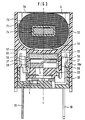
- the relay shown in FIGS. 1 to 3 essentially consists of a base 1 with an armature 3 pivotably arranged above the base.
- a base body 5 receives the base 1 from below and forms a closed contact space 4 with it.
- the base body 5 an upwardly open coil space 6, in which a coil 7 is inserted.
- the base 1 has a flat bottom 11, which defines the base level of the relay, and partially raised peripheral sides 12.
- contact carriers 13 with exposed fixed contacts 14 are punched out parallel to the base level 8 and punched out; in one piece with the contact carriers, connection pins 15 are formed downwards, which usually serve as solder connections.
- contact spring connecting pins 16 are embedded from the board material, the extensions of which serve upward as bearing supports 16 a for the armature 3.
- the armature 3 consists of an essentially elongated ferromagnetic sheet which has an upwardly curved bearing curvature 31 in its central section to define a rolling axis running transversely to its longitudinal extent.
- the two wings of the armature each define pole faces 32 in their end sections.
- a movable contact arrangement with an insulating jacket 33 is arranged, in which two elongated contact springs 34 are embedded in a plane next to each other, such that their ends are exposed below the armature ends and each carry movable contacts 35, which with the underlying fixed contacts 14 work together.
- Each contact spring has an im Lateral area emerging from the sheath 33, in the area of the armature bearing arched and angled into a vertical position, the bearing band 36, which is welded to an associated contact spring connecting pin 16 with a corresponding fastening section 37 or is conductively connected to it in some other way.
- the insulating sheath 33 has upwardly formed pins 38 which are inserted through bores in the armature 3 and deformed on the upper side thereof, so that the movable contact arrangement with the contact springs 34 is firmly connected to the armature 3 and thus takes part in its switching movement.
- the desired contact distance between the movable contacts 35 and the fixed contacts 14 is first set in a suitable manner before the bearing strips 36 are connected to the connecting pins 16.
- the base body 5 made of insulating material has a generally H-shaped cross section with a partition 51 parallel to the base plane and circumferential side walls 52, which together with the partition 51 form the switching space 4 mentioned below and the coil space 6 upwards.
- two bushings 53 are recessed, in which two ferromagnetic yokes 54 are inserted standing vertically.
- a rod-shaped permanent magnet 55 is fastened between clamping ribs 56 (see FIG. 3) between the lower ends of the two yokes 54.
- the permanent magnet is magnetized in three poles in such a way that it generates a permanent magnet pole (N) in the center above the armature axis and two opposite poles (S) at both ends.
- paragraphs 57 are formed below the partition 51, which lie above the connecting pins 15 and 16 and, if necessary, can serve as support areas for corresponding extended connecting pins. In any case, these paragraphs provide additional stiffening of the base body; special configurations will be described later.
- the coil 7 has a coil body 71 made of insulating material, on which a winding 73 is arranged between flanges 72.
- a core 74 is arranged in an axial through opening of the coil former.
- each coil terminal pins 75 are anchored in the flanges 72.
- the coil 7 is inserted from above into the coil space 6 of the base body, the coil connection pins 75 being inserted through corresponding holes 58 in the base body.
- the coil is then fixed in the base body with potting compound, the yokes 54 and the permanent magnet 55 also being glued.
- the bushings are also tightly sealed. Filling the coil space 6 with potting compound creates a very stable bond that can also absorb high mechanical forces.
- a plate 76 is placed above the coil, which offers a flat surface for labeling.
- the plate can be made of metal or be coated with metal so that it forms a heat shield when the relay is exposed to strong heat radiation, for example in SMT assembly.
- the base 1 pre-assembled with the armature 3 is inserted into the switching space 4 of the base body, the side walls 52 of the base body engaging in a box shape over the side walls 12 of the base.
- the base 1 is pushed in so far that the bearing curvature 31 bears more or less on the permanent magnet 55 and the armature can optionally abut one of the yokes.
- the switching mobility of the armature can be checked by inserting a test pin through ventilation openings 17 (shown in FIG. 8) and measuring the switching movement.
- two ventilation or test openings 17, one under each anchor wing, are provided. These are located in the middle between the two contact springs in the area of a raised insulating web 18.
- the base 1 After setting the exact position between the armature and the permanent magnet or yoke, the base 1 is firmly connected to the base body 5, preferably by casting of potting compound or adhesive in the edge gap between the respective side walls.
- the ventilation and test openings 17 can later be closed separately.
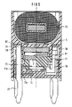
- FIGS. 3, 4 and 5 for example, a groove 63 is formed in the contact space below the shoulders 57, which is delimited by the outer wall 52 of the base body and by a wall web 59.
- This wall web 59 also forms an insulation between the metal parts of the armature and the connection elements or bearing strips 36 of the contact springs.
- potting compound 63 can be poured into these grooves in order to firmly anchor projecting connecting pins in the base body; this also increases the rigidity.
- FIG. 4 shows an embodiment of connection pins 20 which is inserted in the base area through the injected circuit board of the contact carrier 13 and is contacted in a suitable manner in openings 13a.
- the connection pins 20 with a rectangular cross section are anchored at their upper end section 21 in the sealing compound 60 and are bent outwards with their lower ends in the form of SMT connection lugs 22.
- round connecting pins 23 are anchored in the base in the same way and contacted with the carrier board 13.
- the upper end sections 24 are anchored in the casting compound 60, while the lower ends in this case are deformed into press-in handles 25.
- the press-in pins can also have a rectangular cross-section as in FIG. 4 or some other cross-sectional shape.
- the relay according to FIGS. 4 and 5 has the same or similar structure as that shown previously; minor modifications are possible within the scope of the invention.
- a particularly simple way of attaching and contacting the pins 20 and 23 is that in the Contact carrier 13 forming plate openings 13a are recessed, which have a slightly smaller cross section than the pins 20 and 23 to be inserted. Depending on the cross-sectional shape of the pins, these openings 13a are also round or rectangular.
- the recesses 11a in the base 1 or in the base base 11, on the other hand, are somewhat larger in cross section than the pins 20 or 23, so that the edge of the openings 13a around the pins is somewhat exposed.
- FIG. 5 a laterally protruding bearing journal 41 is additionally shown in the right half of the anchor representation, which lies in a bearing shell 61 of the base body or of the wall web 59.
- the armature can, if necessary, be positioned more precisely in relation to the base body and the permanent magnet 55.
- the storage is thus independent of the shape and properties of the bearing belts 36.
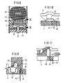
- These bearing belts 36 are unnecessary in this case and can be replaced by a simple flexible connecting section 42, as shown in FIGS. 6 and 7.
- the area of the armature bearing from FIG. 6 is shown again in detail in FIG. 9, the section here being moved somewhat outward into the side wall of the base body in order to show the bearing shell 61.
- the meandering connecting section 42 has an integrally molded connecting pin 43 which is guided through an opening 19 in the base to the outside.
- the opening 19 is closed and the connecting pin 43 is fixed by a locking pin 62 formed on the base body.
- the bearing part of the armature is again shown schematically from the side.
- connection section 42 is extrusion-coated in its horizontal and obliquely upward part by the sheath 33 of the contact arrangement, so that only the vertical part acts resiliently.
- a closure piece 44 is sprayed onto the connection section.
- FIG. 12 shows that a meandering or also differently shaped connection section 42 can also be connected to a solid connection pin 23 anchored in the base, similar to that in FIG. 5, instead of a molded-on thin connection pin.
- the pin 23 is in this case inserted through a recess 45 of the connecting portion 42 and conductively connected to it in a manner not shown.
- FIGS. 13 and 14 show a further modification in two detailed views, the armature being supported as before by a bearing journal 41 and the contact springs each having a round connection section 42, which runs from the armature to the outside as a torsion bar parallel to the bearing axis Pin 23 are connected.
- FIGS. 15 and 16 A further modification of the armature bearing is shown in FIGS. 15 and 16, which largely correspond to the representation in FIGS. 6 and 7.
- the armature is mounted on the permanent magnet 55 via an additional bearing piece 46, which forms a bearing cutting edge 47.
- the armature has a bearing notch 48 formed in its axial area which, like the bearing cutting edge, has an obtuse angle of any kind or can also be rounded.
- the contact springs In this case, 34 are connected to a connecting pin 23 via a meandering connecting section 42.
Landscapes
- Physics & Mathematics (AREA)
- Electromagnetism (AREA)
- Switch Cases, Indication, And Locking (AREA)
- Electromagnets (AREA)
Applications Claiming Priority (2)
| Application Number | Priority Date | Filing Date | Title |
|---|---|---|---|
| DE19520220A DE19520220C1 (de) | 1995-06-01 | 1995-06-01 | Polarisiertes elektromagnetisches Relais |
| DE19520220 | 1995-06-01 |
Publications (3)
| Publication Number | Publication Date |
|---|---|
| EP0746007A2 true EP0746007A2 (fr) | 1996-12-04 |
| EP0746007A3 EP0746007A3 (fr) | 1998-04-15 |
| EP0746007B1 EP0746007B1 (fr) | 2000-04-19 |
Family
ID=7763482
Family Applications (1)
| Application Number | Title | Priority Date | Filing Date |
|---|---|---|---|
| EP96108869A Expired - Lifetime EP0746007B1 (fr) | 1995-06-01 | 1996-05-29 | Relais électromagnétique polarisé |
Country Status (4)
| Country | Link |
|---|---|
| US (1) | US5673012A (fr) |
| EP (1) | EP0746007B1 (fr) |
| JP (1) | JPH08329810A (fr) |
| DE (2) | DE19520220C1 (fr) |
Families Citing this family (19)
| Publication number | Priority date | Publication date | Assignee | Title |
|---|---|---|---|---|
| DE19606884C1 (de) * | 1996-02-23 | 1997-04-30 | Schrack Components Ag | Elektromagnetisches Relais |
| DE19635277C1 (de) * | 1996-08-30 | 1998-02-12 | Siemens Ag | Verfahren zur Herstellung des Ankerhubs eines Relais |
| DE19635275C1 (de) * | 1996-08-30 | 1998-02-05 | Siemens Ag | Polarisiertes Relais |
| JP2998680B2 (ja) * | 1997-02-27 | 2000-01-11 | 日本電気株式会社 | 高周波リレー |
| DE19713659C1 (de) * | 1997-04-02 | 1998-06-25 | Siemens Ag | Elektromagnetisches Relais |
| DE19719357C1 (de) * | 1997-05-07 | 1998-10-22 | Siemens Ag | Elektromagnetisches Relais |
| DE19719355C1 (de) * | 1997-05-07 | 1998-11-05 | Siemens Ag | Polarisiertes elektromagnetisches Relais |
| DE19727863C1 (de) * | 1997-06-30 | 1999-01-21 | Siemens Ag | Elektromagnetisches Relais |
| DE19816878C2 (de) | 1998-04-17 | 2003-11-13 | Hengstler Gmbh | Zwillingsrelais |
| DE19825077C1 (de) * | 1998-06-04 | 2000-03-30 | Siemens Ag | Polarisiertes elektromagnetisches Relais |
| DE19825078C1 (de) * | 1998-06-04 | 2000-03-09 | Siemens Ag | Polarisiertes elektromagnetisches Relais |
| DE19837241C1 (de) * | 1998-08-17 | 2000-07-27 | Tyco Electronics Logistics Ag | Elektromagnetisches Relais |
| DE19941402C1 (de) * | 1999-08-31 | 2001-05-31 | Tyco Electronics Logistics Ag | Relais mit Wippanker |
| US7111929B2 (en) * | 2001-08-14 | 2006-09-26 | Hewlett-Packard Development Company, Lp | Magnetically-actuated fluid control valve |
| DE102011083953A1 (de) * | 2011-10-04 | 2013-04-04 | Tyco Electronics Amp Gmbh | Fixier- und Überwachungsvorrichtung |
| IN2014KN01161A (fr) * | 2011-12-20 | 2015-10-16 | Siemens Ag | |
| DE102012006436B4 (de) | 2012-03-30 | 2020-01-30 | Phoenix Contact Gmbh & Co. Kg | Gepoltes elektromagnetisches Relais und Verfahren zu seiner Herstellung |
| JP6115195B2 (ja) * | 2013-03-08 | 2017-04-19 | オムロン株式会社 | 電磁継電器 |
| KR102772341B1 (ko) * | 2019-08-14 | 2025-02-25 | 현대자동차주식회사 | 릴레이 |
Family Cites Families (9)
| Publication number | Priority date | Publication date | Assignee | Title |
|---|---|---|---|---|
| DE2723430C2 (de) * | 1977-05-24 | 1984-04-26 | Siemens AG, 1000 Berlin und 8000 München | Elektromagnetisches Relais |
| DE3430589A1 (de) * | 1984-08-20 | 1986-02-27 | Siemens AG, 1000 Berlin und 8000 München | Sockel fuer ein elektromagnetisches relais |
| US5015978A (en) * | 1987-05-29 | 1991-05-14 | Nec Corporation | Electromagnetic relay |
| DE3938226C1 (en) * | 1989-11-17 | 1991-05-23 | E. Dold & Soehne Kg, 7743 Furtwangen, De | Miniature switching relay of H=section - providing double insulated chamber for magnet and contact systems |
| EP0437209B1 (fr) * | 1990-01-12 | 1995-11-29 | Omron Corporation | Relais électromagnétique |
| JPH04149924A (ja) * | 1990-10-15 | 1992-05-22 | Nec Corp | 電磁継電器 |
| JP3472881B2 (ja) * | 1993-02-24 | 2003-12-02 | オムロン株式会社 | 電磁継電器の製造方法 |
| DE59401271D1 (de) * | 1993-03-24 | 1997-01-23 | Siemens Ag | Polarisiertes elektromagnetisches relais |
| DE4410285C2 (de) * | 1994-03-24 | 1997-09-18 | Siemens Ag | Leiterplattenrelais mit Einpreßanschlüssen |
-
1995
- 1995-06-01 DE DE19520220A patent/DE19520220C1/de not_active Expired - Fee Related
-
1996
- 1996-05-29 EP EP96108869A patent/EP0746007B1/fr not_active Expired - Lifetime
- 1996-05-29 DE DE59604985T patent/DE59604985D1/de not_active Expired - Fee Related
- 1996-05-31 JP JP8138951A patent/JPH08329810A/ja not_active Withdrawn
- 1996-06-03 US US08/659,048 patent/US5673012A/en not_active Expired - Fee Related
Also Published As
| Publication number | Publication date |
|---|---|
| DE19520220C1 (de) | 1996-11-21 |
| JPH08329810A (ja) | 1996-12-13 |
| EP0746007A3 (fr) | 1998-04-15 |
| DE59604985D1 (de) | 2000-05-25 |
| US5673012A (en) | 1997-09-30 |
| EP0746007B1 (fr) | 2000-04-19 |
Similar Documents
| Publication | Publication Date | Title |
|---|---|---|
| EP0746007B1 (fr) | Relais électromagnétique polarisé | |
| DE60018502T2 (de) | Elektromagnetisches Relais | |
| EP0281950B1 (fr) | Relais électromagnétique | |
| EP0691030B1 (fr) | Relais electromagnetique polarise | |
| DE2454967A1 (de) | Elektromagnetisches relais | |
| EP0780870A2 (fr) | Rélais électromagnétique monostable de petite dimension | |
| EP0129068B1 (fr) | Relais électromagnétique miniaturisé et méthode de fabrication | |
| DE19537612C1 (de) | Elektromagnetisches Relais und Verfahren zu dessen Herstellung | |
| EP0894327B1 (fr) | Relais electromagnetique | |
| EP0758484B1 (fr) | Relais modulaire | |
| WO1997027604A1 (fr) | Relais electromagnetique de structure etroite et procede permettant de le produire | |
| DE29521012U1 (de) | Polarisiertes elektromagnetisches Relais | |
| DE19713659C1 (de) | Elektromagnetisches Relais | |
| EP0846330B1 (fr) | Relais electromagnetique et son utilisation sur une carte de circuits imprimes | |
| EP0077017B1 (fr) | Relais électromagnétique polarisé | |
| EP0074577A1 (fr) | Relais électromagnétique polarisé | |
| DE19719357C1 (de) | Elektromagnetisches Relais | |
| DE4309618A1 (de) | Polarisiertes elektromagnetisches Relais | |
| DE3232380C2 (fr) | ||
| EP0291019B1 (fr) | Relais électromagnétique | |
| DE3100817A1 (de) | Polarisiertes elektromagnetisches relais | |
| DE19719355C1 (de) | Polarisiertes elektromagnetisches Relais | |
| EP0897586B1 (fr) | Relais electromagnetique | |
| DE3637115A1 (de) | Gepoltes flachrelais | |
| EP0133582A2 (fr) | Relais électromagnétique |
Legal Events
| Date | Code | Title | Description |
|---|---|---|---|
| PUAI | Public reference made under article 153(3) epc to a published international application that has entered the european phase |
Free format text: ORIGINAL CODE: 0009012 |
|
| AK | Designated contracting states |
Kind code of ref document: A2 Designated state(s): CH DE FR GB IT LI |
|
| PUAL | Search report despatched |
Free format text: ORIGINAL CODE: 0009013 |
|
| AK | Designated contracting states |
Kind code of ref document: A3 Designated state(s): CH DE FR GB IT LI |
|
| 17P | Request for examination filed |
Effective date: 19980505 |
|
| GRAG | Despatch of communication of intention to grant |
Free format text: ORIGINAL CODE: EPIDOS AGRA |
|
| GRAG | Despatch of communication of intention to grant |
Free format text: ORIGINAL CODE: EPIDOS AGRA |
|
| GRAH | Despatch of communication of intention to grant a patent |
Free format text: ORIGINAL CODE: EPIDOS IGRA |
|
| 17Q | First examination report despatched |
Effective date: 19990924 |
|
| GRAH | Despatch of communication of intention to grant a patent |
Free format text: ORIGINAL CODE: EPIDOS IGRA |
|
| GRAA | (expected) grant |
Free format text: ORIGINAL CODE: 0009210 |
|
| RAP1 | Party data changed (applicant data changed or rights of an application transferred) |
Owner name: TYCO ELECTRONICS LOGISTICS AG |
|
| RIN1 | Information on inventor provided before grant (corrected) |
Inventor name: DITTMANN, MICHAEL Inventor name: STADLER, HEINZ |
|
| AK | Designated contracting states |
Kind code of ref document: B1 Designated state(s): CH DE FR GB IT LI |
|
| PG25 | Lapsed in a contracting state [announced via postgrant information from national office to epo] |
Ref country code: IT Free format text: LAPSE BECAUSE OF FAILURE TO SUBMIT A TRANSLATION OF THE DESCRIPTION OR TO PAY THE FEE WITHIN THE PRE;WARNING: LAPSES OF ITALIAN PATENTS WITH EFFECTIVE DATE BEFORE 2007 MAY HAVE OCCURRED AT ANY TIME BEFORE 2007. THE CORRECT EFFECTIVE DATE MAY BE DIFFERENT FROM THE ONE RECORDED.SCRIBED TIME-LIMIT Effective date: 20000419 |
|
| REG | Reference to a national code |
Ref country code: CH Ref legal event code: EP |
|
| PGFP | Annual fee paid to national office [announced via postgrant information from national office to epo] |
Ref country code: CH Payment date: 20000522 Year of fee payment: 5 |
|
| REF | Corresponds to: |
Ref document number: 59604985 Country of ref document: DE Date of ref document: 20000525 |
|
| ET | Fr: translation filed | ||
| GBT | Gb: translation of ep patent filed (gb section 77(6)(a)/1977) |
Effective date: 20000609 |
|
| PLBE | No opposition filed within time limit |
Free format text: ORIGINAL CODE: 0009261 |
|
| STAA | Information on the status of an ep patent application or granted ep patent |
Free format text: STATUS: NO OPPOSITION FILED WITHIN TIME LIMIT |
|
| 26N | No opposition filed | ||
| PG25 | Lapsed in a contracting state [announced via postgrant information from national office to epo] |
Ref country code: LI Free format text: LAPSE BECAUSE OF NON-PAYMENT OF DUE FEES Effective date: 20010628 Ref country code: CH Free format text: LAPSE BECAUSE OF NON-PAYMENT OF DUE FEES Effective date: 20010628 |
|
| REG | Reference to a national code |
Ref country code: GB Ref legal event code: IF02 |
|
| REG | Reference to a national code |
Ref country code: CH Ref legal event code: PL |
|
| PGFP | Annual fee paid to national office [announced via postgrant information from national office to epo] |
Ref country code: GB Payment date: 20030401 Year of fee payment: 8 |
|
| PGFP | Annual fee paid to national office [announced via postgrant information from national office to epo] |
Ref country code: FR Payment date: 20030505 Year of fee payment: 8 |
|
| PG25 | Lapsed in a contracting state [announced via postgrant information from national office to epo] |
Ref country code: GB Free format text: LAPSE BECAUSE OF NON-PAYMENT OF DUE FEES Effective date: 20040529 |
|
| GBPC | Gb: european patent ceased through non-payment of renewal fee | ||
| PG25 | Lapsed in a contracting state [announced via postgrant information from national office to epo] |
Ref country code: FR Free format text: LAPSE BECAUSE OF NON-PAYMENT OF DUE FEES Effective date: 20050131 |
|
| REG | Reference to a national code |
Ref country code: FR Ref legal event code: ST |
|
| PGFP | Annual fee paid to national office [announced via postgrant information from national office to epo] |
Ref country code: DE Payment date: 20050630 Year of fee payment: 10 |
|
| PG25 | Lapsed in a contracting state [announced via postgrant information from national office to epo] |
Ref country code: DE Free format text: LAPSE BECAUSE OF NON-PAYMENT OF DUE FEES Effective date: 20061201 |