EP0746247B1 - Trocart guide sous controle visuel - Google Patents
Trocart guide sous controle visuel Download PDFInfo
- Publication number
- EP0746247B1 EP0746247B1 EP94925159A EP94925159A EP0746247B1 EP 0746247 B1 EP0746247 B1 EP 0746247B1 EP 94925159 A EP94925159 A EP 94925159A EP 94925159 A EP94925159 A EP 94925159A EP 0746247 B1 EP0746247 B1 EP 0746247B1
- Authority
- EP
- European Patent Office
- Prior art keywords
- light transmission
- trocar
- imaging member
- surgical
- light
- Prior art date
- Legal status (The legal status is an assumption and is not a legal conclusion. Google has not performed a legal analysis and makes no representation as to the accuracy of the status listed.)
- Expired - Lifetime
Links
- 238000003384 imaging method Methods 0.000 claims description 27
- 230000005540 biological transmission Effects 0.000 claims description 25
- 238000003780 insertion Methods 0.000 claims description 14
- 230000037431 insertion Effects 0.000 claims description 14
- 230000035515 penetration Effects 0.000 claims description 13
- 239000012780 transparent material Substances 0.000 claims description 9
- 239000004033 plastic Substances 0.000 claims description 4
- 210000003813 thumb Anatomy 0.000 claims description 4
- 239000011796 hollow space material Substances 0.000 claims 3
- 210000004247 hand Anatomy 0.000 claims 1
- 210000000683 abdominal cavity Anatomy 0.000 description 31
- 238000000034 method Methods 0.000 description 23
- 239000000835 fiber Substances 0.000 description 10
- 210000004204 blood vessel Anatomy 0.000 description 7
- 229910001220 stainless steel Inorganic materials 0.000 description 7
- 239000010935 stainless steel Substances 0.000 description 7
- 210000001015 abdomen Anatomy 0.000 description 6
- 230000008878 coupling Effects 0.000 description 6
- 238000010168 coupling process Methods 0.000 description 6
- 238000005859 coupling reaction Methods 0.000 description 6
- 210000001835 viscera Anatomy 0.000 description 6
- 210000003815 abdominal wall Anatomy 0.000 description 5
- 238000013461 design Methods 0.000 description 5
- 239000000463 material Substances 0.000 description 5
- 238000001356 surgical procedure Methods 0.000 description 5
- 238000012800 visualization Methods 0.000 description 5
- CURLTUGMZLYLDI-UHFFFAOYSA-N Carbon dioxide Chemical compound O=C=O CURLTUGMZLYLDI-UHFFFAOYSA-N 0.000 description 4
- 230000003187 abdominal effect Effects 0.000 description 4
- 239000004020 conductor Substances 0.000 description 4
- 238000010276 construction Methods 0.000 description 4
- 208000027418 Wounds and injury Diseases 0.000 description 3
- 239000000919 ceramic Substances 0.000 description 3
- 230000006378 damage Effects 0.000 description 3
- 210000003811 finger Anatomy 0.000 description 3
- 208000014674 injury Diseases 0.000 description 3
- 210000000056 organ Anatomy 0.000 description 3
- 239000007787 solid Substances 0.000 description 3
- 229910002092 carbon dioxide Inorganic materials 0.000 description 2
- 239000001569 carbon dioxide Substances 0.000 description 2
- 210000003414 extremity Anatomy 0.000 description 2
- 238000010348 incorporation Methods 0.000 description 2
- 238000002357 laparoscopic surgery Methods 0.000 description 2
- 238000000465 moulding Methods 0.000 description 2
- 230000000149 penetrating effect Effects 0.000 description 2
- 230000008569 process Effects 0.000 description 2
- 239000004065 semiconductor Substances 0.000 description 2
- 230000003213 activating effect Effects 0.000 description 1
- 239000000853 adhesive Substances 0.000 description 1
- 230000001070 adhesive effect Effects 0.000 description 1
- 239000012472 biological sample Substances 0.000 description 1
- 238000002192 cholecystectomy Methods 0.000 description 1
- 238000002405 diagnostic procedure Methods 0.000 description 1
- 239000011521 glass Substances 0.000 description 1
- 239000007943 implant Substances 0.000 description 1
- 238000012830 laparoscopic surgical procedure Methods 0.000 description 1
- 239000002184 metal Substances 0.000 description 1
- 238000012986 modification Methods 0.000 description 1
- 230000004048 modification Effects 0.000 description 1
- 230000003287 optical effect Effects 0.000 description 1
- 238000003825 pressing Methods 0.000 description 1
- 230000005180 public health Effects 0.000 description 1
- 230000003014 reinforcing effect Effects 0.000 description 1
- 230000000284 resting effect Effects 0.000 description 1
- 238000007789 sealing Methods 0.000 description 1
- 230000000007 visual effect Effects 0.000 description 1
Images


Classifications
-
- A—HUMAN NECESSITIES
- A61—MEDICAL OR VETERINARY SCIENCE; HYGIENE
- A61B—DIAGNOSIS; SURGERY; IDENTIFICATION
- A61B1/00—Instruments for performing medical examinations of the interior of cavities or tubes of the body by visual or photographical inspection, e.g. endoscopes; Illuminating arrangements therefor
- A61B1/00064—Constructional details of the endoscope body
- A61B1/00071—Insertion part of the endoscope body
- A61B1/0008—Insertion part of the endoscope body characterised by distal tip features
- A61B1/00087—Tools
-
- A—HUMAN NECESSITIES
- A61—MEDICAL OR VETERINARY SCIENCE; HYGIENE
- A61B—DIAGNOSIS; SURGERY; IDENTIFICATION
- A61B1/00—Instruments for performing medical examinations of the interior of cavities or tubes of the body by visual or photographical inspection, e.g. endoscopes; Illuminating arrangements therefor
- A61B1/00131—Accessories for endoscopes
- A61B1/00135—Oversleeves mounted on the endoscope prior to insertion
-
- A—HUMAN NECESSITIES
- A61—MEDICAL OR VETERINARY SCIENCE; HYGIENE
- A61B—DIAGNOSIS; SURGERY; IDENTIFICATION
- A61B17/00—Surgical instruments, devices or methods
- A61B17/34—Trocars; Puncturing needles
- A61B17/3417—Details of tips or shafts, e.g. grooves, expandable, bendable; Multiple coaxial sliding cannulas, e.g. for dilating
-
- A—HUMAN NECESSITIES
- A61—MEDICAL OR VETERINARY SCIENCE; HYGIENE
- A61B—DIAGNOSIS; SURGERY; IDENTIFICATION
- A61B90/00—Instruments, implements or accessories specially adapted for surgery or diagnosis and not covered by any of the groups A61B1/00 - A61B50/00, e.g. for luxation treatment or for protecting wound edges
- A61B90/36—Image-producing devices or illumination devices not otherwise provided for
- A61B90/37—Surgical systems with images on a monitor during operation
- A61B2090/373—Surgical systems with images on a monitor during operation using light, e.g. by using optical scanners
Definitions
- This invention relates to the field of operative and diagnostic laparoscopic surgical procedures and in particular to a new and improved visually directed trocar laparoscopic instrument and method of use for conducting such procedures.
- EP-A-0135364 discloses a trocar assembly having a piercing tip of stainless steel or some other suitable material.
- the piercing tip includes three blades, each blade having a cutting edge.
- US-A-3961621 discloses a surgical tool for taking biological samples in which a stiletto having a sharp edge is provided inside a needle. A core of light-conducting fibres is provided inside the stiletto.
- a surgical penetration device comprising:
- a new and improved laparoscopic instrument is provided with an elongated, hollow trocar having a tipped end suitable for insertion through layers of human skin and flesh forming the walls of a cavity with the tipped end being fabricated from light transparent material.
- the tipped end of light transparent material preferably is shaped to form a light transmission and imaging element for projecting light outwardly into an abdominal or other cavity of a patient, and for receiving back and directing light images onto a suitable light image receptor of a conventional miniaturized light telescope designed for surgical purposes.
- the tipped end of light transparent material is formed to pierce human flesh.
- a cutting member which can be formed of metal or ceramic for example, is adapted to cooperate with the tipped end of light transparent material to provide the tipped end with a cutting edge for piercing human flesh to permit surgical insertion of the tipped end through human flesh and into a body cavity.
- the hollow trocar has a central passageway formed therein of sufficient diameter to accommodate the elements of a miniaturized light telescope together with essential power supply conductors for energizing the light source and light receptors such as a bundle of fiber optic light coupling elements for deriving and providing back light images usable for laparoscopic diagnostic procedures even while the trocar is being surgically inserted through the navel and is penetrating through the layers of skin and abdominal wall of a patient and on into the abdominal cavity.
- essential power supply conductors for energizing the light source and light receptors
- a bundle of fiber optic light coupling elements for deriving and providing back light images usable for laparoscopic diagnostic procedures even while the trocar is being surgically inserted through the navel and is penetrating through the layers of skin and abdominal wall of a patient and on into the abdominal cavity.
- the laparoscopic instrument includes a hollow tubular trocar sleeve that surrounds and encloses the trocar for a substantial portion of its length to form a combined trocar and sleeve assembly.
- the trocar is slidable lengthwise relative to the trocar sleeve whereby the trocar can be removed after visually controlled physical placement of the trocar and sleeve assembly into the abdominal wall of a patient's abdominal cavity at a desired location and to a desired depth.
- the trocar then can be replaced with a somewhat large fiber optic light telescope and video imaging system, and other remotely manipulatable surgical instrument inserted through the central opening of the trocar sleeve in a conventional known manner.
- the invention makes available a new and improved laparoscopic procedure comprising mounting a miniaturized light telescope with light source together with suitable miniaturized power supply conductors, and fiber optic coupling and light receptor elements in the hollow trocar prior to starting the laparoscopic procedure.
- the light telescope then is energized from an electric power source and the output of the light receptors supplied to a video display.
- the tipped and lighted end of the trocar with or without the cutting member is placed at a point, such as the navel, on a patient's abdomen to be penetrated while observing such placement on the video display.
- the cutting member may appear as a line or narrow band on the video display and does not obscure vision through the light transparent material.
- the lighted trocar then is surgically inserted by being pressed slowly and carefully into and through the walls of the patient's abdomen while observing the progress of the trocar assembly as it travels into and through the wall of the abdominal or other cavity.
- the operator by properly controlling orientation and progress of the trocar tip, can assure that the trocar does not penetrate into the abdominal cavity at a place or for a distance where it might injure any blood vessels within the abdominal cavity walls or internal organs within the abdominal cavity.
- a handle provided on the trocar facilitates manipulation and control of the trocar tip penetration.
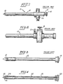
- Figures 1, 2 and 3 of the drawings illustrate a prior art, known trocar and sleeve assembly now being used by the medical profession in performing laparoscopic procedures such as laparoscopic cholecystectomies. Other similar laparoscopic procedures can be performed using the instrument.
- Figure 1 is an elevational side view of a known combined trocar and trocar sleeve assembly 11 comprised by an elongated, solid, stainless steel trocar 12, best seen in Figure 3, and a hollow, tubular trocar sleeve 15 shown in Figure 2.
- Trocar 12 includes a pointed tipped end 13, which may be either pyramidal or the like or conical in configuration, and is sufficiently sharp to be able to penetrate and be physically pressed through the navel, layers of skin and abdominal walls of a patient in order to provide access to the interior of the abdominal cavity.
- Trocar 12 is a solid rod of appropriate diameter, for example of from 6 to 9 millimeters in diameter, and terminates in a push cap 14 that facilitates surgical insertion of the stiff elongated rod 12 into and through the navel of a patient by pushing on cap 14.
- Trocar sleeve 15 is a cylindrical hollow tube fabricated from biologically compatible material, such as stainless steel.
- Sleeve 15 has a central opening into which the trocar 12 fits in a relatively tight manner, but is sufficiently loose to allow trocar 12 to be slid lengthwise relative to the sleeve 15 and withdrawn.
- Trocar sleeve 15 in most applications also includes at least one trumpet valve 16 as shown in both Figures 1 and 2 as well as one or more insufflation stopcocks shown at 17 in Figure 2. These elements all are of known construction and operation and need not be described in detail with respect to the present invention. In use the assembled trocar and sleeve appear as shown at 11 in Figure 1 of the drawings.
- the trocar 12 After insertion of the trocar and sleeve assembly 11, the trocar 12 is withdrawn from the trocar sleeve 15 leaving the sleeve with its appended elements such as the trumpet valve 16 and insufflation stopcock 17 extending into the abdominal cavity.
- a light telescope with a miniaturized light source of conventional commercially available construction is inserted through the central opening of the trocar sleeve 15 to establish visualization of the intra-abdominal organs. Once clear visualization is established, a variety of surgical procedures can be carried out safely through the use of remotely operable surgical instruments inserted into the interior of the abdominal cavity through the central passageway in the trocar sleeve 15 in a known manner. Upon completion of the procedures, all instruments including the light telescope are withdrawn along with the trocar sleeve and the opening through which they were inserted is sewn up.
- the step of introducing the trocar and sleeve assembly into the abdominal cavity using conventional known techniques is a blind procedure and frequently causes injury to blood vessels in the walls of the abdominal cavity and organs located within the abdominal cavity close to the point of entry.
- FIG 4 is a longitudinal sectional view taken along the longitudinal axis of an elongated, cylindrically-shaped trocar having a hollow tubular body 21 fabricated from an inflexible material (such as stainless steel) that is compatible with human flesh.
- Trocar 21 has a tipped end 22 that is sufficiently sharp that it can be surgically inserted through layers of skin and human flesh by physically pressing on a push cap 23 secured to the opposite end of the trocar.
- Tipped end 22 is fabricated from light transparent material such as glass or a space-age plastic and is shaped to form a light transmission and imaging element for projecting light outwardly into an abdominal or other cavity of a patient and for directing light images received back onto a suitable light image receptor 24.
- Tipped end 22 also has a substantially solid piercing point, as shown in Figure 4, which can be of pyramidal or the like or conical configuration. As shown in Figures 4 and 7, for example, a tapered portion of the tipped end 22 projects from the tubular body 21 and a non-tapered portion of the tipped end 22 is recessed in the tubular body 21.
- Light image receptor 24 is part of a commercially available, miniaturized, medical light telescope for surgical use and is not part of this invention.
- Receptor 24 may comprise a plurality of light receiving input ends of a bundle of fiber optic light coupling elements (not shown) or alternatively a semiconductor light to electric signal transducer.
- Trocar 21 has a central opening 25 which is of sufficient diameter to accommodate passage of the elements of the miniaturized light telescope such as a light source 26 comprised by a bundle of fiber optic elements, a semiconductor laser or a light bulb together with essential power supply conductors and/or fiber optic light coupling elements (not shown).
- These elements serve to energize light source 26 and light receptors 24 (or transducers if required) together with fiber optical or electric signal coupling elements for deriving and supplying video signals to a video camera 27, comprising a part of the light telescope system.
- the video camera 27 excites a suitable video monitor (not shown) for producing video images usable for diagnostic and surgical purposes even while the trocar is being surgically inserted into and is penetrating the layers of skin on the navel prior to proceeding into the abdominal cavity.
- Trocar 21 shown in Figure 4 is designed for use with a trocar sleeve 28 shown in Figure 5.
- Trocar sleeve 28 comprises an elongated hollow tubular body of stainless steel or other similar material having an open end through which the tipped transparent end 22 of trocar 21 projects and a rubber sealing cap 29 on the opposite end.
- a trumpet valve 16 and insufflation stopcock, such as 17 shown in Figure 2 are included on the hollow trocar sleeve 28.
- the trocar sleeve 15 shown in Figure 2 and trocar sleeve 28 in Figure 5 can be made to be interchangeable.
- Trocar sleeve 28 is designed to physically surround and enclose trocar 21 for a substantial portion of its length to form a combined trocar and sleeve assembly shown in Figure 6 of the drawings.
- the trocar 21 is slidable lengthwise relative to trocar sleeve 28 so that the trocar can be removed after visual surgical insertion of the trocar 21 and sleeve 28 assembly into the abdominal cavity of a patient at a desired location and to a desired depth.
- Figure 7 illustrates an alternative design of the trocar 21 wherein suitable handles shown at 32 and 33 are provided on opposite sides of the elongated tubular body of the trocar 21 at the end opposite transparent tip end 22.
- the trocar of Figure 7 is similar to that described with relation to Figure 4. Surgical insertion of the trocar 21 of Figure 7 and trocar sleeve 28 in assembled relation as depicted by Figure 6, through the navel of a patient can be better accomplished and more easily guided using the handles 32 and 33 while visually observing the progress of the trocar through the layers of skin and abdominal walls of a patient.
- FIGs 8A and 8B illustrate another alternative design of the trocar 21.
- a handle 36 preferably formed of plastic, is affixed at or proximate an end 38 of the trocar 21, opposite the tipped end 22. As shown in Figure 8A, the handle 36 extends away from the trocar 21 so as to avoid interference with the central opening 25 at the trocar end 38.
- the handle 36 includes a finger contour portion 40 to accommodate the individual fingers and is sufficiently elongated to permit gripping by all of the fingers.
- a thumb flange 42 is provided on each side of the handle 36 for right or left handed users to rest their thumb during exertion of manual pressure on the trocar 21 in the direction of the tipped end 22.
- the handle 36 further includes a mounting portion 44 adjacent the thumb flange 42 which encircles the trocar at the end 38 and can be bonded or otherwise secured to the trocar end 38.
- FIG 9 illustrates an alternative design of the tipped end 22 as used on the trocar 21.
- the tipped end 22 which is shown for example as a three-sided pyramidal tip, is combined with a cutter member 50.
- the cutter member 50 which can be formed of a suitable hardened material such as stainless steel or ceramic for example, includes V-shaped (in cross-section) cutting portions 52, 54 and 56 that wrap onto the pyramidal corners of the tipped end 22 as shown in Figure 11.
- Each of the cutting portions 52, 54 and 56 have sharp edges that converge to a common sharp point 60 as shown in Figure 9.
- An annular reinforcing ring 62 joins the cutting portions 52, 54 and 56.
- the cutting member 50 can be formed as a separate member and placed as an insert in a mold for molding the tipped end 22 from plastic.
- the cutting member 50 and the tipped end 22 can be separately formed and bonded together with a suitable know medical grade adhesive.
- the cutting member 50 can also be modified to include four cutting portions for incorporation in a tipped end 22 of a four-sided pyramidal configuration.
- the cutting member 50 can be incorporated in a tipped end 22 of conical configuration, wherein the cutting edges 58 project slightly from the curved conical surface.
- Figure 12 illustrates a further alternative design of the tipped end 22 as used on the trocar 21.
- the cutter member 70 which can be formed of stainless steel or ceramic for example, includes bar-like cutting portions 72, 74 and 76 that are partly disposed within the tipped end 22 in alignment with the pyramidal corners of the tipped end as shown in Figure 14.
- Each of the cutting portions 72, 74 and 76 have sharp edges 78 that converge to a common sharp point 80 as shown in Figure 12.
- the cutting portions 72, 74 and 76 can be imbedded in the tipped end 22 up to the sharp edge 78 as shown in Figure 14 or the sharp edge 78 can project slightly as shown in Figure 15.
- the cutting member 70 can also be modified to include four cutting portions for incorporation in a tipped end 22 of four-sided pyramidal configuration.
- the cutting member 70 can be incorporated in a tipped end of conical configuration in the arrangement such as shown in Figures 14 or 15.
- Molding of a tipped end 22 with the cutting member 70 is in accordance with the manner previously described for the tipped end 22 of Figures 9-11.
- the conical tipped end 22 can include a cutting member 50 or 70 that has a single cutting portion extending across opposite sides of the conical tipped end.
- the cutting members 50 and 70 need not extend to the pointed extremity of the tipped end 22, thereby enabling the pointed extremity of the tipped end 22 to pass light.
- the procedure is commenced by activating the miniaturized light telescope including the light source and suitable miniaturized light receptors, power supply conductors and fiber optic couplings provided in the assembled hollow trocar and sleeve, while using the trocar of any of Figures 4-15, prior to starting the procedure.
- the light source is activated, any output from the light receptors 24 is supplied to a video display console (not shown) via video receiver 27.
- the tipped and lighted end of the trocar 21 then is placed at the point on the patient's abdomen (such as the navel) to be penetrated while observing such placement on the video display.
- the trocar and sleeve assembly then is pushed slowly into and through the layers of skin and support flesh of the patient's navel while observing the progress of the trocar assembly on the video display while it travels into and through the navel.
- the cutting edges appear as lines or narrow bands and do not obscure vision through the light telescope and do not obscure the video display.
- the positioning of the trocar can be adjusted by the laparoscopic surgeon, if necessary, by manipulation of the push cap 23 and/or side handles 32 and 33, or the handle 36, to assure that the trocar does not penetrate into the abdominal cavity at a place or for a distance where it might penetrate and injure blood vessels in the walls of the cavity or internal organs within the abdominal cavity.
- the combined assembly of trocar 21 and trocar sleeve 28 are inserted together with the light source and video display components of the miniaturized light telescope contained therein.
- the trocar 21 together with its light source and video display components is removed from sleeve 28 which remains implanted in the abdominal cavity.
- the trocar 21 then is replaced in implanted sleeve 28 with the fiber optic light source and video imaging system of the miniaturized light telescope along with any other assorted remotely manipulatable surgical instruments, as needed, which are inserted through the central opening in the trocar sleeve in a conventional known manner.
- This invention provides to the medical profession a new laparoscopic instrument which allows the laparoscopic surgeon to enter the abdominal cavity of a patient under conditions where he can directly, visually follow the progress of the pointed tip of the instrument as it passes through the layers of skin and supporting walls of the abdominal cavity. Hence, prior to entering the abdominal cavity to any great depth, the surgeon can observe whether there are any blood vessels in the supporting walls or internal organs which would be punctured or otherwise damaged if the trocar is allowed to penetrate too deeply at a selected point.
- the new procedure and instrument will eliminate many major and minor complications associated with the prior known blind invasive laparoscopic surgical techniques employed to implant the laparoscopic trocar and sleeve assembly into the abdominal cavity.
Landscapes
- Health & Medical Sciences (AREA)
- Life Sciences & Earth Sciences (AREA)
- Surgery (AREA)
- Animal Behavior & Ethology (AREA)
- Public Health (AREA)
- Engineering & Computer Science (AREA)
- Biomedical Technology (AREA)
- Heart & Thoracic Surgery (AREA)
- Medical Informatics (AREA)
- Molecular Biology (AREA)
- Pathology (AREA)
- General Health & Medical Sciences (AREA)
- Nuclear Medicine, Radiotherapy & Molecular Imaging (AREA)
- Veterinary Medicine (AREA)
- Physics & Mathematics (AREA)
- Biophysics (AREA)
- Optics & Photonics (AREA)
- Radiology & Medical Imaging (AREA)
- Endoscopes (AREA)
- Surgical Instruments (AREA)
- Apparatus For Radiation Diagnosis (AREA)
- Laser Surgery Devices (AREA)
Claims (11)
- Dispositif de pénétration chirurgicale comprenant :(a) un élément allongé rigide (21) ayant une première extrémité, caractérisé par(b) un élément d'imagerie et de transmission de la lumière (22) formé essentiellement d'une matière transparente, fournie au niveau de la première extrémité dudit élément allongé, afin de former une extension dudit élément allongé et de projeter de la lumière et recevoir des images lumineuses,(c) un moyen coupant (22) comportant un élément coupant pouvant coopérer avec ledit élément d'imagerie et de transmission de la lumière afin de fournir au dit élément d'imagerie et de transmission de la lumière un bord coupant afin de transpercer la chair d'un être humain et de permettre l'insertion chirurgicale dudit élément d'imagerie et de transmission de la lumière à travers la chair d'un être humain dans une cavité corporelle, et(d) ledit élément allongé ayant un moyen (25) permettant de contenir un moyen d'éclairement traditionnel et un moyen de réception d'image lumineuse traditionnel, sous la forme d'un télescope traditionnel afin de coopérer avec ledit élément d'imagerie et de transmission de la lumière, ledit moyen formant conteneur ayant des dimensions permettant une insertion détachable, par coulissement, du télescope traditionnel dans l'élément allongé et le retrait, par coulissement, du télescope traditionnel de l'élément allongé.
- Dispositif de pénétration chirurgicale selon la revendication 1, dans lequel ledit élément d'imagerie et de transmission de la lumière présente une surface extérieure et ledit élément coupant est réuni à la surface extérieure dudit élément d'imagerie et de transmission de la lumière.
- Dispositif de pénétration chirurgicale selon la revendication 1, dans lequel ledit élément d'imagerie et de transmission de la lumière présente une surface extérieure et ledit élément coupant est conçu pour s'étendre au-delà ladite surface extérieure, afin de transpercer la chair d'un être humain et de permettre l'insertion chirurgicale dudit élément d'imagerie et de transmission de la lumière à travers la chair d'un être humain.
- Dispositif de pénétration chirurgicate selon la revendication 3, dans lequel ledit élément coupant comporte un bord de lame (52, 54, 56 ; 72, 74, 76) faisant saillie à partir dudit élément d'imagerie et de transmission de la lumière.
- Dispositif de pénétration chirurgicale selon la revendication 1, dans lequel ledit élément coupant comporte une pluralité de bords de lames (52, 54, 56 ; 72, 74, 76) dans des plans sécants.
- Dispositif de pénétration chirurgicale selon la revendication 1, dans lequel ledit élément d'imagerie et de transmission de la lumière est constitué de plastique et ledit élément coupant est intégré dans ledit élément d'imagerie et de transmission de la lumière.
- Dispositif de pénétration chirurgicale selon la revendication 6, dans lequel ledit élément coupant comporte une pluralité de bords de lames dans des plans sécants, qui font saillie à partir dudit élément d'imagerie et de transmission de la lumière.
- Dispositif de pénétration chirurgicale selon la revendication 1, comportant des moyens de saisie (23, 36) réunis au dit élément allongé, afin de permettre une manipulation à une seule main dudit élément allongé et de permettre à cette dite seule main d'exercer simultanément une pression manuelle sur ledit élément allongé dans la direction dudit élément d'imagerie et de transmission de la lumière pour une insertion chirurgicale dudit élément d'imagerie et de transmission de la lumière, à travers la chair d'un être humain, dans une cavité corporelle.
- Dispositif de pénétration chirurgicale selon la revendication 8, dans lequel ledit moyen de saisie présente un appui pour le pouce (42), pour les mains gauche et droite, afin de permettre l'utilisation dudit moyen de saisie avec l'une ou l'autre main.
- Dispositif de pénétration chirurgicale selon la revendication 1, ledit élément allongé rigide est tubulaire, avec un espace creux, ledit espace creux prévu dans ledit élément allongé rigide s'étendant jusqu'au dit élément d'imagerie et de transmission de la lumière, et ledit espace creux constituant le moyen formant conteneur permettant de contenir le moyen d'éclairement traditionnel et le moyen de réception d'images lumineuses traditionnel, sous la forme d'un télescope traditionnel.
- Dispositif de pénétration chirurgicale selon la revendication 1, dans lequel l'élément d'imagerie et de transmission de la lumière forme une fermeture au niveau de la première extrémité dudit élément allongé rigide.
Applications Claiming Priority (9)
| Application Number | Priority Date | Filing Date | Title |
|---|---|---|---|
| WOPCT/US93/11109 | 1993-11-16 | ||
| PCT/US1993/011109 WO1994011040A1 (fr) | 1992-11-17 | 1993-11-16 | Trocart dirige par controle visuel et procede d'utilisation |
| US08/153,632 US5376076A (en) | 1992-11-17 | 1993-11-17 | Visually directed trocar for laparoscopic surgical procedures and method of using same |
| US153628 | 1993-11-17 | ||
| US08/153,628 US5551947A (en) | 1992-11-17 | 1993-11-17 | Visually directed trocar for laparoscopic surgical procedures and method of using same |
| US153625 | 1993-11-17 | ||
| US153632 | 1993-11-17 | ||
| US08/153,625 US5380291A (en) | 1992-11-17 | 1993-11-17 | Visually directed trocar for laparoscopic surgical procedures and method of using same |
| PCT/US1994/008683 WO1995013751A1 (fr) | 1993-11-16 | 1994-07-29 | Trocart guide sous controle visuel et procede associe |
Publications (3)
| Publication Number | Publication Date |
|---|---|
| EP0746247A1 EP0746247A1 (fr) | 1996-12-11 |
| EP0746247A4 EP0746247A4 (fr) | 1997-11-19 |
| EP0746247B1 true EP0746247B1 (fr) | 2004-09-08 |
Family
ID=27492634
Family Applications (1)
| Application Number | Title | Priority Date | Filing Date |
|---|---|---|---|
| EP94925159A Expired - Lifetime EP0746247B1 (fr) | 1993-11-16 | 1994-07-29 | Trocart guide sous controle visuel |
Country Status (6)
| Country | Link |
|---|---|
| EP (1) | EP0746247B1 (fr) |
| AU (1) | AU693468B2 (fr) |
| CA (1) | CA2176565C (fr) |
| DE (1) | DE69433986T2 (fr) |
| ES (1) | ES2227530T3 (fr) |
| WO (1) | WO1995013751A1 (fr) |
Families Citing this family (8)
| Publication number | Priority date | Publication date | Assignee | Title |
|---|---|---|---|---|
| US5685820A (en) * | 1990-11-06 | 1997-11-11 | Partomed Medizintechnik Gmbh | Instrument for the penetration of body tissue |
| US7470230B2 (en) | 2005-03-31 | 2008-12-30 | Tyco Healthcare Group Lp | Optical obturator |
| JP5248596B2 (ja) | 2007-04-17 | 2013-07-31 | タイコ ヘルスケア グループ リミテッド パートナーシップ | ハンドル付き視覚化栓塞子 |
| US8192353B2 (en) | 2007-10-05 | 2012-06-05 | Tyco Healthcare Group Lp | Visual obturator |
| US9226774B2 (en) | 2009-12-17 | 2016-01-05 | Covidien Lp | Visual obturator with tip openings |
| US10463399B2 (en) * | 2014-11-06 | 2019-11-05 | Asimion Inc. | Visually assisted entry of a Veress needle with a tapered videoscope for microlaparoscopy |
| US11382662B2 (en) | 2017-08-04 | 2022-07-12 | The Brigham And Women's Hospital, Inc. | Trocars and veress-type needles with illuminated guidance and safety features |
| WO2019028458A1 (fr) | 2017-08-04 | 2019-02-07 | Brigham And Women's Hospital, Inc. | Aiguilles de type veress dotées d'éléments de guidage et de sécurité éclairées |
Family Cites Families (4)
| Publication number | Priority date | Publication date | Assignee | Title |
|---|---|---|---|---|
| DK131542C (da) * | 1974-02-06 | 1976-02-09 | Akad Tekn Videnskaber | Kirurgisk instrument til udtagning af biologiske prover |
| US4601710B1 (en) * | 1983-08-24 | 1998-05-05 | United States Surgical Corp | Trocar assembly |
| DE4035146A1 (de) * | 1990-11-06 | 1992-05-07 | Riek Siegfried | Instrument zum penetrieren von koerpergewebe |
| US5334150A (en) * | 1992-11-17 | 1994-08-02 | Kaali Steven G | Visually directed trocar for laparoscopic surgical procedures and method of using same |
-
1994
- 1994-07-29 AU AU75183/94A patent/AU693468B2/en not_active Expired
- 1994-07-29 ES ES94925159T patent/ES2227530T3/es not_active Expired - Lifetime
- 1994-07-29 EP EP94925159A patent/EP0746247B1/fr not_active Expired - Lifetime
- 1994-07-29 WO PCT/US1994/008683 patent/WO1995013751A1/fr not_active Ceased
- 1994-07-29 CA CA002176565A patent/CA2176565C/fr not_active Expired - Lifetime
- 1994-07-29 DE DE69433986T patent/DE69433986T2/de not_active Expired - Lifetime
Also Published As
| Publication number | Publication date |
|---|---|
| ES2227530T3 (es) | 2005-04-01 |
| EP0746247A1 (fr) | 1996-12-11 |
| AU7518394A (en) | 1995-06-06 |
| AU693468B2 (en) | 1998-07-02 |
| WO1995013751A1 (fr) | 1995-05-26 |
| CA2176565C (fr) | 1997-03-18 |
| DE69433986D1 (de) | 2004-10-14 |
| EP0746247A4 (fr) | 1997-11-19 |
| DE69433986T2 (de) | 2005-02-03 |
| CA2176565A1 (fr) | 1995-05-26 |
Similar Documents
| Publication | Publication Date | Title |
|---|---|---|
| US5720761A (en) | Visually directed trocar and method | |
| US5551947A (en) | Visually directed trocar for laparoscopic surgical procedures and method of using same | |
| US5609562A (en) | Visually directed trocar and method | |
| US5323766A (en) | Illuminating endo-photocoagulation probe | |
| JP3774818B2 (ja) | 体組織の貫通のための装置 | |
| US5431151A (en) | Instrument for the penetration of body tissue | |
| US8469876B2 (en) | Endoscopic devices and method of use | |
| US6908427B2 (en) | Flexible endoscope capsule | |
| US5074867A (en) | Surgical instrument assembly and related surgical method | |
| AU648341B2 (en) | A medical device for and a method of endoscopic surgery | |
| CA2141023C (fr) | Applicateur de tube d'alimentation gastrostomique percutanee et methode | |
| WO1994011040B1 (fr) | Trocart dirige par controle visuel et procede d'utilisation | |
| JPH07178100A (ja) | 鉗子状ニードルホルダーを有する器具 | |
| US20020156346A1 (en) | Endoscopic devices and method of use | |
| JPH0595953A (ja) | ニードルガイド | |
| US6663605B2 (en) | Removable protective cannula for use in surgery | |
| EP0746247B1 (fr) | Trocart guide sous controle visuel | |
| JP2000245689A (ja) | 内視鏡挿入用補助具 | |
| US20060183973A1 (en) | Endoscopic devices and method of use | |
| JPH0654862A (ja) | 照明付き外科用カニユーレ | |
| JP2859826B2 (ja) | 穿刺針ガイド付き超音波探触子 | |
| US8465412B2 (en) | Uterine devices and method of use | |
| JPH0565180B2 (fr) | ||
| AU4183189A (en) | Stem for surgical suture apparatus |
Legal Events
| Date | Code | Title | Description |
|---|---|---|---|
| PUAI | Public reference made under article 153(3) epc to a published international application that has entered the european phase |
Free format text: ORIGINAL CODE: 0009012 |
|
| 17P | Request for examination filed |
Effective date: 19960522 |
|
| AK | Designated contracting states |
Kind code of ref document: A1 Designated state(s): DE ES FR GB IT |
|
| A4 | Supplementary search report drawn up and despatched |
Effective date: 19971003 |
|
| AK | Designated contracting states |
Kind code of ref document: A4 Designated state(s): DE ES FR GB IT |
|
| RAP1 | Party data changed (applicant data changed or rights of an application transferred) |
Owner name: ETHICON ENDO-SURGERY, INC. |
|
| 17Q | First examination report despatched |
Effective date: 20010719 |
|
| RTI1 | Title (correction) |
Free format text: VISUALLY DIRECTED TROCAR |
|
| RTI1 | Title (correction) |
Free format text: VISUALLY DIRECTED TROCAR |
|
| RTI1 | Title (correction) |
Free format text: VISUALLY DIRECTED TROCAR |
|
| GRAP | Despatch of communication of intention to grant a patent |
Free format text: ORIGINAL CODE: EPIDOSNIGR1 |
|
| GRAS | Grant fee paid |
Free format text: ORIGINAL CODE: EPIDOSNIGR3 |
|
| GRAA | (expected) grant |
Free format text: ORIGINAL CODE: 0009210 |
|
| AK | Designated contracting states |
Kind code of ref document: B1 Designated state(s): DE ES FR GB IT |
|
| REG | Reference to a national code |
Ref country code: GB Ref legal event code: FG4D |
|
| REF | Corresponds to: |
Ref document number: 69433986 Country of ref document: DE Date of ref document: 20041014 Kind code of ref document: P |
|
| REG | Reference to a national code |
Ref country code: ES Ref legal event code: FG2A Ref document number: 2227530 Country of ref document: ES Kind code of ref document: T3 |
|
| PLBE | No opposition filed within time limit |
Free format text: ORIGINAL CODE: 0009261 |
|
| STAA | Information on the status of an ep patent application or granted ep patent |
Free format text: STATUS: NO OPPOSITION FILED WITHIN TIME LIMIT |
|
| ET | Fr: translation filed | ||
| 26N | No opposition filed |
Effective date: 20050609 |
|
| PGFP | Annual fee paid to national office [announced via postgrant information from national office to epo] |
Ref country code: ES Payment date: 20130628 Year of fee payment: 20 Ref country code: DE Payment date: 20130724 Year of fee payment: 20 |
|
| PGFP | Annual fee paid to national office [announced via postgrant information from national office to epo] |
Ref country code: GB Payment date: 20130724 Year of fee payment: 20 Ref country code: FR Payment date: 20130724 Year of fee payment: 20 |
|
| PGFP | Annual fee paid to national office [announced via postgrant information from national office to epo] |
Ref country code: IT Payment date: 20130717 Year of fee payment: 20 |
|
| REG | Reference to a national code |
Ref country code: DE Ref legal event code: R071 Ref document number: 69433986 Country of ref document: DE |
|
| REG | Reference to a national code |
Ref country code: GB Ref legal event code: PE20 Expiry date: 20140728 |
|
| REG | Reference to a national code |
Ref country code: ES Ref legal event code: FD2A Effective date: 20141007 |
|
| PG25 | Lapsed in a contracting state [announced via postgrant information from national office to epo] |
Ref country code: DE Free format text: LAPSE BECAUSE OF EXPIRATION OF PROTECTION Effective date: 20140730 |
|
| PG25 | Lapsed in a contracting state [announced via postgrant information from national office to epo] |
Ref country code: GB Free format text: LAPSE BECAUSE OF EXPIRATION OF PROTECTION Effective date: 20140728 |
|
| PG25 | Lapsed in a contracting state [announced via postgrant information from national office to epo] |
Ref country code: ES Free format text: LAPSE BECAUSE OF EXPIRATION OF PROTECTION Effective date: 20140730 |