EP0747193A2 - Vorrichtung zur Herstellung eines kontinuierlichen Schaumformkörpers - Google Patents
Vorrichtung zur Herstellung eines kontinuierlichen Schaumformkörpers Download PDFInfo
- Publication number
- EP0747193A2 EP0747193A2 EP96108073A EP96108073A EP0747193A2 EP 0747193 A2 EP0747193 A2 EP 0747193A2 EP 96108073 A EP96108073 A EP 96108073A EP 96108073 A EP96108073 A EP 96108073A EP 0747193 A2 EP0747193 A2 EP 0747193A2
- Authority
- EP
- European Patent Office
- Prior art keywords
- mold
- molding
- cover
- bottom wall
- side walls
- Prior art date
- Legal status (The legal status is an assumption and is not a legal conclusion. Google has not performed a legal analysis and makes no representation as to the accuracy of the status listed.)
- Granted
Links
- 238000000465 moulding Methods 0.000 title claims abstract description 82
- 239000004033 plastic Substances 0.000 title claims abstract description 30
- 229920003023 plastic Polymers 0.000 title claims abstract description 30
- 230000013011 mating Effects 0.000 claims description 9
- 238000000605 extraction Methods 0.000 description 8
- 239000012530 fluid Substances 0.000 description 5
- 239000008187 granular material Substances 0.000 description 5
- 238000003466 welding Methods 0.000 description 5
- 238000006073 displacement reaction Methods 0.000 description 4
- 230000006641 stabilisation Effects 0.000 description 4
- 238000011105 stabilization Methods 0.000 description 4
- 238000010276 construction Methods 0.000 description 3
- 238000004519 manufacturing process Methods 0.000 description 3
- 239000000463 material Substances 0.000 description 3
- 125000006850 spacer group Chemical group 0.000 description 3
- 238000009435 building construction Methods 0.000 description 2
- 229920006248 expandable polystyrene Polymers 0.000 description 2
- 238000010438 heat treatment Methods 0.000 description 2
- 238000009413 insulation Methods 0.000 description 2
- 238000000034 method Methods 0.000 description 2
- 238000012986 modification Methods 0.000 description 2
- 230000004048 modification Effects 0.000 description 2
- 229920000426 Microplastic Polymers 0.000 description 1
- 230000003213 activating effect Effects 0.000 description 1
- 238000004891 communication Methods 0.000 description 1
- 238000001816 cooling Methods 0.000 description 1
- 239000012809 cooling fluid Substances 0.000 description 1
- 239000000498 cooling water Substances 0.000 description 1
- 238000005520 cutting process Methods 0.000 description 1
- 230000009977 dual effect Effects 0.000 description 1
- 239000004794 expanded polystyrene Substances 0.000 description 1
- 239000002783 friction material Substances 0.000 description 1
- 230000000977 initiatory effect Effects 0.000 description 1
- 238000002347 injection Methods 0.000 description 1
- 239000007924 injection Substances 0.000 description 1
- 239000011810 insulating material Substances 0.000 description 1
- -1 polytetrafluorethylene Polymers 0.000 description 1
- 229920001343 polytetrafluoroethylene Polymers 0.000 description 1
- 230000000717 retained effect Effects 0.000 description 1
- 238000003860 storage Methods 0.000 description 1
Images




Classifications
-
- B—PERFORMING OPERATIONS; TRANSPORTING
- B29—WORKING OF PLASTICS; WORKING OF SUBSTANCES IN A PLASTIC STATE IN GENERAL
- B29C—SHAPING OR JOINING OF PLASTICS; SHAPING OF MATERIAL IN A PLASTIC STATE, NOT OTHERWISE PROVIDED FOR; AFTER-TREATMENT OF THE SHAPED PRODUCTS, e.g. REPAIRING
- B29C44/00—Shaping by internal pressure generated in the material, e.g. swelling or foaming ; Producing porous or cellular expanded plastics articles
- B29C44/20—Shaping by internal pressure generated in the material, e.g. swelling or foaming ; Producing porous or cellular expanded plastics articles for articles of indefinite length
- B29C44/26—Shaping by internal pressure generated in the material, e.g. swelling or foaming ; Producing porous or cellular expanded plastics articles for articles of indefinite length using several expanding steps
-
- B—PERFORMING OPERATIONS; TRANSPORTING
- B29—WORKING OF PLASTICS; WORKING OF SUBSTANCES IN A PLASTIC STATE IN GENERAL
- B29C—SHAPING OR JOINING OF PLASTICS; SHAPING OF MATERIAL IN A PLASTIC STATE, NOT OTHERWISE PROVIDED FOR; AFTER-TREATMENT OF THE SHAPED PRODUCTS, e.g. REPAIRING
- B29C33/00—Moulds or cores; Details thereof or accessories therefor
- B29C33/30—Mounting, exchanging or centering
- B29C33/301—Modular mould systems [MMS], i.e. moulds built up by stacking mould elements, e.g. plates, blocks, rods
-
- B—PERFORMING OPERATIONS; TRANSPORTING
- B29—WORKING OF PLASTICS; WORKING OF SUBSTANCES IN A PLASTIC STATE IN GENERAL
- B29C—SHAPING OR JOINING OF PLASTICS; SHAPING OF MATERIAL IN A PLASTIC STATE, NOT OTHERWISE PROVIDED FOR; AFTER-TREATMENT OF THE SHAPED PRODUCTS, e.g. REPAIRING
- B29C44/00—Shaping by internal pressure generated in the material, e.g. swelling or foaming ; Producing porous or cellular expanded plastics articles
- B29C44/34—Auxiliary operations
- B29C44/58—Moulds
Definitions
- the present invention relates to an apparatus for molding a continuous foamed plastic element.
- the present invention relates to an apparatus for molding a continuous foamed plastic element comprising a substantially parallelepipedic central body and, optionally, at least one lug laterally and longitudinally extending from said body, which finds a preferred but not mandatory use as a building construction component.
- continuous foamed plastic element means a foamed plastic section bar, e.g. made of foamed polystyrene, which leaves the molding apparatus as a single piece substantially free from joints or breaks and having indefinite length.
- foamed plastic construction elements preferably made of foamed polystyrene, in the form of sheets or section bars of appropriate shape and size, having the function of thermal and acoustic insulating material.
- the construction elements of the type considered are obtained by cutting in pieces of predetermined length a continuous element produced by means of molding apparatuses comprising a mold in which a molding seat is defined having a shape mating that of the continuous element to be produced.
- a metered quantity of expandable plastic material in granules is fed into the above mentioned seat and subjected to expansion with a mutual welding of the granules through the action of heat, so as to form a new portion of the continuous element and obtain its simultaneous welding with an adjacent portion formed in a preceding molding cycle.
- the mold is opened and the continuous element incorporating the new portion is made to advance by a distance corresponding to the length of the molding seat, so as to arrange the latter for receiving other granules and initiating a new production cycle.
- the molding apparatus of the prior art displays poor operating flexibility and, more specifically, does not allow an easy control of the shape, and in particular of the height, of the continuous foamed plastic element where required.
- the prior art proposes to change the height of the molding seat defined in the mold, by inserting spacers of adequate thickness into the cover each time as needed.
- the technical problem underlying the present invention is therefore that of providing an apparatus for molding a continuous foamed plastic element capable of overcoming the above-mentioned shortcomings of the prior art.
- an apparatus for molding a continuous foamed plastic element comprising:
- the height of the molding seat for the foamed plastic element may be advantageously controlled in a substantially continuous manner between a minimum and a maximum predetermined design value by means of at least one powered mechanical jack.
- the above mentioned means designed to control the displacement of the mold cover comprises a pair of mechanical jacks kinematically connected together by means of a shaft rotated by the above mentioned powered means.
- an adequate parallelism may be provided to the raising/descending movement of the cover away from and towards the bottom wall of the mold.
- an apparatus for molding a continuous foamed plastic element of the type comprising a substantially parallelepipedic central body and at least one lateral lug laterally and longitudinally extending from said central body, said apparatus including:
- the height of the second molding cavity, in which the side lug of the foamed plastic element is molded may be advantageously controlled in a substantially continuous manner between predetermined design minimum and maximum values by means of at least one mechanical jack equipped with respective power means.
- the grooved side wall defining - together with the bottom wall of the mold - the second molding cavity for the side lug is equipped with a pair of mechanical jacks kinematically connected together by means of a shaft rotated by the above mentioned power means.
- an adequate parallelism may be provided to the raising/descending movement of the cover away from and towards the bottom wall of the mold.
- an apparatus for molding a continuous foamed plastic element of the above mentioned type characterized in that it further comprises first and second means for independently and adjustably positioning said cover and said at least one side wall away from and towards said bottom wall of the mold to control in an adjustable and substantially continuous manner the height of said first and, respectively, said second molding cavities.
- the height of the first molding cavity of the foamed plastic element - or at least its overall height - may be in this case controlled simultaneously and independently of that of the molding cavity defining its side lugs.
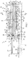
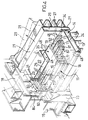
- reference number 1 indicates as a whole an apparatus according to the present invention for molding a continuous foamed plastic element, such as for example a continuous element 15 designed for the construction of floors.
- the element 15 comprises a body 16, in which are longitudinally defined a plurality of parallel cavities 17, as well as a pair of lugs 18, 19 extending laterally and longitudinally from opposite parts of the body 16 (FIG. 4).
- the apparatus 1 comprises a mold 2 mounted on a supporting structure including a side panel 4, substantially rectangular in shape, as well as a substantially cage-like structure, globally indicated by 10, which are fixed in a known manner to a pair of parallel beams 3a, 3b.
- the cage-like structure 10 comprises, more specifically, two pairs of posts 5a-5b and 5c-5d parallel with one another and symmetrically arranged on opposite sides of apparatus 1.
- each of the above mentioned pairs 5a-5b and 5c-5d are mutually spaced and reciprocally stiffened by respective cross-pieces 6, 7 extending parallel to the mold 2.
- the posts 5a-5c and 5b-5d are in turn mutually spaced and stiffened by a second pair of cross-pieces 8, 9 extending perpendicularly to the mold 2.
- the mold 2 of molding apparatus 1 essentially comprises a bottom wall 14, a pair of opposite and parallel side walls 20, 21 and a cover 22 defining - in cooperation with a vertical head 23 - a substantially tunnel-shaped molding seat, having a shape mating that of element 15.
- the bottom wall 14 of the mold 2 is supported by a horizontal supporting frame 13 while the side walls 20, 21 and the cover 22 of the mold 2 are fixed to respective supporting and stiffening beams indicated by 28, 29 and 30.
- the bottom wall 14, side walls 20, 21 and cover 22 of the mold are fixed to the supporting frame 13 and to the supporting beams 28-30 in a removable manner by means of known fastening means such as e.g. bolts or lever clamping means.
- the mold 2 also comprises, as better explained below, a first zone 2a for expanding the plastic material in granules and for actually molding a portion of predetermined length of the element 15 and a second zone 2b, adjacent to the former, designed to allow a shape stabilization of the portion molded in a previous operating cycle.
- the vertical head 23 is essentially made up of a hollow body fixed in a known manner (not shown) to the horizontal supporting frame 13 on which the bottom wall 14 of the mold 2 is mounted in a removable manner.
- the horizontal supporting frame 13 is in turn supported by beams 3a, 3b of apparatus 1 through a pair of substantially bridge-like supporting elements 11, 12.
- a grooved plate 80 Onto the vertical head 23 is fixed a grooved plate 80, preferably lined with a low-friction material, such as for example polytetrafluorethylene, designed to form at one end of the element 15 a corresponding grooved surface having a mating form.
- a low-friction material such as for example polytetrafluorethylene
- This grooved surface allows to obtain, as clarified below, an optimal mutual welding between adjacent portions of element 15 molded by the apparatus 1 during sequential molding cycles.
- the aforementioned vertical head 23 closes at one end the molding seat defined in the mold 2 whose opposite end is closed in a removable manner by a sidewall 56 supported in a rotating manner by the horizontal supporting frame 13 by means of a hinge 57.
- the sidewall 56 is angularly movable between a first position wherein it opens zone 2b of the mold 2 and a second position, wherein it closes said zone, in which is retained in a removable manner by appropriate clasping means fixed to the beam 30 supporting the cover 22.
- the clasping means of the sidewall 56 comprises a groove 68, transversely formed in the beam 30 at the free end of the cover 22 of the mold 2, in which the free end of the sidewall 56 is received in a removable manner with a mating fit.
- bottom wall 14, side walls 20, 21 and cover 22 of the mold 2 are essentially constituted by hollow boxed bodies in which adjacent chambers, structurally independent from one another are defined, having a length substantially equal to the length of zones 2a and, respectively, 2b of the mold.
- each of the above mentioned chambers is also equipped with a plurality of slots or holes all indicated by 48.
- the side walls 20 and 21 of the mold 2 comprise, in the embodiment illustrated, respective grooves 31, 32 substantially L-shaped, longitudinally extending for the entire length of side walls 20 and 21.
- grooves possess a predetermined height and depth defined during design as a function of the particular shape it is desired to impart to lugs 18, 19 of the element 15.
- a first molding cavity 35 for the central body 16, as well as opposite second molding cavities 33, 34 for the side lugs 18 and 19 of the element 15 are defined within the mold 2 and in the above mentioned molding seat.
- the second molding cavities 33, 34 are in particular defined between the above mentioned L-shaped grooves 31 and 32 and the bottom wall 14 of the mold 2.
- the beam 30 supporting the cover 22 of the mold 2 is connected to a supporting frame 36, horizontally extending above the mold 2, by means of an adjustment device 37 which is described in detail hereinbelow.
- the cover 22 may be moved in an adjustable manner by means of the device 37 away from and towards the bottom wall 14 to adjust in a substantially continuous manner the height of the molding cavity 35 of the central body 16 of the element 15.
- the height of the central body 16 of the continuous element 15 may be freely varied between 180 and 320 mm to provide a range of adjustment equal to approximately 140 mm.
- the supporting frame 36 is in turn hinged to the side panel 4 through a pair of parallel hinges 38, 39 having horizontal axes and is supported by the cross-pieces 8 and 9 of the substantially cage-like structure 10, to which the supporting frame 36 is associated, by means of a pair of double-action oil-pressure cylinders 40, 41 (FIG. 3).
- the hinges 38, 39 and the oil-pressure cylinders 40 make up all together an opening device for the cover 22 by means of which the cover may be displaced angularly away from and towards the bottom wall 14 to close and, respectively, open the mold 2.
- the adjusting device 37 of the cover 22 comprises a pair of mechanical jacks 42, 43 supported at a predetermined distance along the supporting frame 36 so as to allow an adequate parallelism of the raising/descending movement of the cover 22.
- the jack 42 which is operated by an electric motor 45 with an interposed gear motor, comprises a gear wheel (not shown) engaged with a rack 46 formed on a rod 47 vertically extending from the beam 30.
- the jack 43 comprises in turn a gear wheel (also not shown) kinematically connected with the gear wheel of the jack 42 through a shaft 49 rotated by the electric motor 45.
- the gear wheel of the jack 43 engages a rack 50 formed on a rod 51, coplanar and parallel to the above mentioned rod 47, vertically extending from the beam 30.
- the beams 28 and 29 supporting and stiffening the side walls 20, 21 of the mold 2 are hinged on opposite sides of the side panel 4 by means of respective pairs of hinges with vertical axes. In FIG. 1 only those hinges indicated by 52 and 53 of the side wall 20 are visible.
- hinges 52, 53 comprise pins 62, 63 of predetermined length coaxially extending in a vertical direction and in which are slidably engaged respective eyelets, 64, 65 extending in mutually spaced relationship from one end of the beam 28.
- the pins 62, 63 of the hinges 52, 53 accordingly define a rotation axis around which is mounted in a rotating manner the side wall 20 operated by an opening device which will be described hereinbelow.
- This opening device comprises, in addition to the above mentioned pair of hinges 52, 53, a pair of coplanar and parallel double-acting oil-pressure cylinders indicated respectively by 54 and 55, supported in a projecting manner by the posts 5a and 5b of the cage-like structure 10.
- Each of the cylinders 54, 55 is equipped with a stem having an eye-shaped free end, engaged in a respective pin 58, 59 of predetermined length and mounted in a known manner onto the beam 28.
- each of the side walls 20, 21 of the mold 2 may be displaced in an adjustable manner away from and towards the bottom wall 14 to adjust the height of the molding cavities 33, 34 of the side lugs 18, 19 of the element 15 by means of respective identical operating and adjusting devices 60, 61 arranged on opposite sides of the mold 2.
- the height of the side lugs 18, 19 of the element 15 may be freely changed between 20 and 80 mm providing a range of adjustment equal to approximately 60 mm.
- the device 60 (FIG. 1) essentially comprises a pair of mechanical jacks 66, 67 supported at a predetermined distance by the substantially bridge-like elements 11, 12 supported by the beams 3a, 3b, so as to allow an adequate parallelism of the raising/descending movement of the side wall 20.
- the jack 66 is operated by an electric motor 71 with an interposed gear motor and comprises a gear wheel (not shown) engaged with a rack 72 formed on a rod 73 associated to the beam 28 supporting the side wall 20.
- the jack 67 which is entirely analogous to the previous one, comprises in turn a gear wheel (also not shown) kinematically connected to the wheel of the jack 66 through a shaft 75 rotated by the electric motor 71.
- the gear wheel of the jack 67 engages a corresponding rack 74 formed on a rod 76, coplanar and parallel to the above mentioned rod 73, associated to the beam 28 supporting the side wall 20.
- each vertical displacement of the side wall 20 is advantageously guided both by the pins 62, 63 of hinges 52, 53 and by the pins 58, 59 mounted on the beam 28 and forming part of the opening device of the side wall 20.
- a plurality of substantially tubular plungers 77 is supported in the mold 2 to define the cavities 17 provided in the body 16 to lighten the element 15 to be produced.
- the plungers 77 having a length substantially equal to that of the mold 2, are mounted in a projecting manner on a moving head 78 and may be withdrawn from or inserted into the internal space of the mold 2 by means of an extraction device 79 which is described in detail below.
- the plungers 77 are slidably mounted in a corresponding plurality of parallel openings 83 formed both in the vertical head 23 of the mold 2 and in the plate 80 integral therewith.
- each plunger 77 having a length equal to that of the zone 2a of the mold, there is also defined - in a manner fully analogous to that of side walls 20, 21, cover 22 and bottom wall 14 of the mold 2 - a chamber 81 designed to distribute in an appropriate sequence appropriate heating and cooling fluids in the zone 2a of the mold.
- the fluids are in particular fed into each chamber 81 through appropriate ducts - not shown - which are in fluid communication with a cavity 84 defined in the moving head 78 at a first end of the plungers 77.
- the plungers 77 are also equipped in an initial portion with a plurality of holes or, alternatively, of slots all indicated by 82.
- the extraction device 79 of the plungers 77 essentially comprises the moving head 78 and a pair of oil-pressure cylinders, respectively upper 85 and lower 86, horizontally extending from the moving head 78 to which they are symmetrically fixed in a known manner at opposite side corners with respect to a longitudinal plane of the apparatus 1.
- the unit comprising the plungers 77, the moving head 78 and the oil-pressure cylinders 85, 86 is slidably mounted on a pair of upper and, respectively lower, supporting rods 87, 88.
- rods 87, 88 are horizontally extending parallel to the oil-pressure cylinders 85 and, respectively, 86 between the side panel 4 and a respective substantially L-shaped supporting element 89, to which they are fixed in a known manner at the free ends of the L-shaped element 89 indicated by references 89a and 89b.
- each of the oil-pressure cylinders 85, 86 is supported by the corresponding rod 87, 88 to which it is engaged by means of a respective tubular sliding blocks 90, 91.
- the rods 87 and 88 simultaneously fulfill both a supporting function and a guide function for the extraction device 79 of the plungers 77, to ensure a strictly horizontal displacement therof away from and towards the mold 2.
- the moving head 78 is positioned against the fixed vertical head 23 and the molding plungers 77 extend into the mold 2 for the entire length of the latter.
- the length of the molding cavities 33, 34 is in this condition substantially equal or little less than that of chambers 24-27 defined within the walls 14, 20, 21 and the cover 22 of the mold 2.
- a predetermined quantity of expandable plastic material in granules e.g. pre-expanded polystyrene
- a predetermined quantity of expandable plastic material in granules e.g. pre-expanded polystyrene
- the above mentioned fluids are in particular fed into (or sucked from) the chambers 22-27 of the walls 14, 20, 21 and 22 of the mold 2, as well as into the chambers 81 defined within the plungers 77, before passing into the molding cavities through the holes 48 and 82.
- the mold 2 is opened by displacing the side walls 20, 21 and the cover 22 away from the bottom wall 14.
- This opening is in particular performed by the oil-pressure cylinders 40, 41 in the case of the cover 22 and 54, 55 in the case of the side wall 20, as well as those acting on the opposite side wall 21.
- the extraction device 79 proceeds to partially extract the plungers 77 from the cavities 17 formed in the element 15.
- This partial extraction is in particular performed by imparting a backward movement to the moving head 78 by means of the oil-pressure cylinders 85, 86 whose stroke is guided by rods 87, 88.
- the oil-pressure cylinders 85, 86 are again activated to bring back the plungers 77 to the original position together with the moving head 78.
- the plungers 77 when the total surface area of the plungers 77 is equal to or preferably greater than the surface area of contact between the element 15 and the bottom wall 14 of the mold 2, the plungers 77 exert during their return travel towards the mold 2 a pulling action on the element 15 which enables to displace the element 15 out of the molding zone 2a of the mold 2.
- the plungers 77 may advantageously constitute respective means for displacing and extracting the continuous element 15, thus allowing to avoid the use of special extraction devices provided on the molding apparatus of the prior art.
- the apparatus 1 is ready to perform a new molding cycle of another portion of the continuous element 15.
- the height of the central body 16 and/or of one or both of the lugs 18, 19 of the element 15, may be easily adjusted by activating the positioning and adjustment device 37 and/or the devices 60 or 61.
- the above mentioned adjustments may be performed in cycle time, i.e. without removing the element 15 previously molded and without interrupting the operation of the apparatus 1.
- the sidewall 56 is overturned downward in the opening position, so as to allow the extraction of the continuous element 15 from the zone 2b of the mold 2 without interruptions.
- the sidewall 56 performs the dual function of hermetically closing the mold and acting as an abutting means capable of holding in position the portion of the previous element 15 located in zone 2b during the molding operations of the first length of the new element having a different height of the central body 16 and/or a different height of one or both of the side lugs 18, 19.
- the above mentioned adjustment may be performed in a substantially continuous manner between minimum and maximum values, determined during design, thanks to the mechanical jacks 42, 43 in the case of the cover 22 and of the mechanical jacks 66, 67 in the case of the side wall 20.
- the height of the central body 16 and of the side lugs 18, 19 may be adjusted - as illustrated for example in FIG. 5 - in an entirely independent manner, so as to meet in a flexible and rapid way the most varied production requirements.
- the apparatus 1 allows to adjust in an extremely flexible manner both the loading characteristics (changed by adjusting the height of the central body 16), and the thermal and acoustic insulation characteristics (changed by adjusting the height of the side lugs 18, 19).
- the apparatus 1 of the present invention also allows a prompt and easy replacement thereof with walls shaped in a different manner so as to obtain continuous elements having the desired size and shape.
Landscapes
- Engineering & Computer Science (AREA)
- Mechanical Engineering (AREA)
- Moulds For Moulding Plastics Or The Like (AREA)
- Casting Or Compression Moulding Of Plastics Or The Like (AREA)
Applications Claiming Priority (3)
| Application Number | Priority Date | Filing Date | Title |
|---|---|---|---|
| ITMI951173 | 1995-06-06 | ||
| ITMI951173A IT1275312B (it) | 1995-06-06 | 1995-06-06 | Apparecchiatura per la formatura di un elemento continuo in materia plastica espansa |
| US08/652,939 US5792481A (en) | 1995-06-06 | 1996-05-24 | Apparatus for molding a continuous foamed plastic element |
Publications (3)
| Publication Number | Publication Date |
|---|---|
| EP0747193A2 true EP0747193A2 (de) | 1996-12-11 |
| EP0747193A3 EP0747193A3 (de) | 1997-04-09 |
| EP0747193B1 EP0747193B1 (de) | 2001-03-14 |
Family
ID=26331289
Family Applications (1)
| Application Number | Title | Priority Date | Filing Date |
|---|---|---|---|
| EP96108073A Expired - Lifetime EP0747193B1 (de) | 1995-06-06 | 1996-05-21 | Vorrichtung zur Herstellung eines kontinuierlichen Schaumformkörpers |
Country Status (5)
| Country | Link |
|---|---|
| US (1) | US5792481A (de) |
| EP (1) | EP0747193B1 (de) |
| DE (1) | DE69612032T2 (de) |
| ES (1) | ES2157364T3 (de) |
| IT (1) | IT1275312B (de) |
Cited By (3)
| Publication number | Priority date | Publication date | Assignee | Title |
|---|---|---|---|---|
| EP0846541A3 (de) * | 1996-12-05 | 1999-06-16 | Plastedil S.A. | Vorrichtung zur Herstellung eines kontinuierlichen Schaumformkörpers mit verstellbarer Wand |
| WO2002034493A1 (en) * | 2000-10-25 | 2002-05-02 | Metecno S.P.A. | Mould for curved panels |
| WO2017115106A1 (en) * | 2015-12-29 | 2017-07-06 | Plastedil S.A. | Apparatus and process for the manufacturing of composite formwork building members and formwork members so manufactured |
Families Citing this family (18)
| Publication number | Priority date | Publication date | Assignee | Title |
|---|---|---|---|---|
| US5945048A (en) * | 1995-03-25 | 1999-08-31 | Ensinger; Wilfried | Process and device for extruding polymer melts to form hollow chamber sections |
| GB9622924D0 (en) * | 1996-11-04 | 1997-01-08 | Alh Syst Ltd | Polymer embedment of rails |
| US20050086904A1 (en) * | 2003-10-23 | 2005-04-28 | Foley Robert P. | Method and apparatus for forming cast wall panels |
| ITMI20040941A1 (it) * | 2004-05-11 | 2005-11-12 | Plastedil Sa | Elemento costruttivo portante in particolare per la realizzazione di solai di edifici e struttura di solaio incorporante tale elemento |
| US8997420B2 (en) * | 2004-11-29 | 2015-04-07 | Victor Amend | Reinforced insulated forms for constructing concrete walls and floors |
| BRPI0607377A2 (pt) | 2005-02-25 | 2010-03-23 | Nova Chem Inc | composiÇço de cimento de baixo peso, leito de estrada, artigo de construÇço painel compàsito, estrutura de concreto isolada, mÉtodo de fabricar um artigo de composiÇço de cimento de baixo peso, artigo de concreto de baixo peso e unidade estrutural de baixo peso |
| CA2598442C (en) | 2005-02-25 | 2011-02-08 | Nova Chemicals Inc. | Composite pre-formed building panels, a building and a framing stud |
| US8752348B2 (en) * | 2005-02-25 | 2014-06-17 | Syntheon Inc. | Composite pre-formed construction articles |
| JP2008534418A (ja) | 2005-03-22 | 2008-08-28 | ノバ・ケミカルズ・インコーポレイテツド | 軽量コンクリート組成物 |
| US7770293B2 (en) * | 2005-10-17 | 2010-08-10 | Victor Amend | Method for manufacturing composite building panels |
| US7677009B2 (en) | 2007-02-02 | 2010-03-16 | Nova Chemicals Inc. | Roof truss system |
| ITMI20071281A1 (it) * | 2007-06-26 | 2008-12-27 | Gilanberry Trading Ltd | Apparecchiatura e metodo per la formatura in continuo di un elemento continuo di materia plastica espansa, impianto comprendente detta apparecchiatura ed elemento costruttivo di materia plastica espansa |
| US8048219B2 (en) | 2007-09-20 | 2011-11-01 | Nova Chemicals Inc. | Method of placing concrete |
| US20090120027A1 (en) * | 2007-11-08 | 2009-05-14 | Victor Amend | Concrete form tie with connector for finishing panel |
| US8567750B2 (en) | 2008-01-11 | 2013-10-29 | Victor Amend | Device having both non-abrading and fire-resistant properties for linking concrete formwork panels |
| CN102133786B (zh) * | 2011-01-27 | 2013-05-08 | 滁州市博精模具设备制造有限公司 | 冰箱箱体发泡模具的涨缩机构 |
| CN106829337A (zh) * | 2015-05-19 | 2017-06-13 | 王振宇 | 一种冰箱发泡自动生产线辅助装置 |
| CN112476937B (zh) * | 2020-12-22 | 2024-08-02 | 安能绿色建筑科技有限公司 | 用于制作建筑保温板材的双底模泡塑成型机 |
Family Cites Families (11)
| Publication number | Priority date | Publication date | Assignee | Title |
|---|---|---|---|---|
| FR1549320A (de) * | 1966-09-13 | 1968-12-13 | ||
| DE1704845A1 (de) * | 1967-08-21 | 1971-05-19 | Metzeler Ag | Verfahren zum Herstellen von Schaumstoffbahnen mit rechteckigem Querschnitt |
| IT1051111B (it) * | 1975-10-24 | 1981-04-21 | Cretti P | Macchina per la formazione con procedimento continuo di profilati pieni e cavi in materiale sintetico espanso |
| US4411413A (en) * | 1980-11-24 | 1983-10-25 | The Budd Company | Apparatus for shoring during the manufacture of a reefer container |
| JPS57113038A (en) * | 1980-12-29 | 1982-07-14 | Yoshihiko Seki | Molding apparatus for foamed plastic object |
| US4505662A (en) * | 1982-01-22 | 1985-03-19 | The Dow Chemical Company | Apparatus for the flexibilization of synthetic resinous foam |
| US4456443A (en) * | 1982-11-26 | 1984-06-26 | Design Engineering Service Inc. | Machine for steam chest molding of foamed material |
| US4588541A (en) * | 1984-11-14 | 1986-05-13 | Fowler James A | Filling of insulating material into building panels |
| IT1202066B (it) * | 1985-05-31 | 1989-02-02 | Piero Cretti | Procedimento per la fabbricazione di elementi in materiale sintetico espanso dotati di strati particolarmente resistenti, impianto per attuare in detto, e prodotti cosi' ottenuti |
| DE8521706U1 (de) * | 1985-07-27 | 1986-03-27 | Moser, Heinrich, 8851 Bissingen | Vorrichtung zum Ausschäumen von insbesondere zur Trittschalldämmung bestimmten Hartschaumstoffplatten oder -blöcken |
| JP2994502B2 (ja) * | 1991-09-21 | 1999-12-27 | 新日本製鐵株式会社 | 成形体連続的製造装置並びに製造方法 |
-
1995
- 1995-06-06 IT ITMI951173A patent/IT1275312B/it active IP Right Grant
-
1996
- 1996-05-21 DE DE69612032T patent/DE69612032T2/de not_active Expired - Lifetime
- 1996-05-21 ES ES96108073T patent/ES2157364T3/es not_active Expired - Lifetime
- 1996-05-21 EP EP96108073A patent/EP0747193B1/de not_active Expired - Lifetime
- 1996-05-24 US US08/652,939 patent/US5792481A/en not_active Expired - Lifetime
Cited By (6)
| Publication number | Priority date | Publication date | Assignee | Title |
|---|---|---|---|---|
| EP0846541A3 (de) * | 1996-12-05 | 1999-06-16 | Plastedil S.A. | Vorrichtung zur Herstellung eines kontinuierlichen Schaumformkörpers mit verstellbarer Wand |
| WO2002034493A1 (en) * | 2000-10-25 | 2002-05-02 | Metecno S.P.A. | Mould for curved panels |
| WO2017115106A1 (en) * | 2015-12-29 | 2017-07-06 | Plastedil S.A. | Apparatus and process for the manufacturing of composite formwork building members and formwork members so manufactured |
| CN108698270A (zh) * | 2015-12-29 | 2018-10-23 | 普莱斯提迪尔公司 | 用于制造组合模板建筑构件的设备和工艺以及如此制造的模板构件 |
| RU2690361C1 (ru) * | 2015-12-29 | 2019-05-31 | Пластедил С.А. | Устройство и способ изготовления элементов составной опалубки и изготовленные таким образом элементы сборной опалубки |
| CN108698270B (zh) * | 2015-12-29 | 2020-08-11 | 普莱斯提迪尔公司 | 用于制造组合模板建筑构件的设备和工艺以及如此制造的模板构件 |
Also Published As
| Publication number | Publication date |
|---|---|
| DE69612032D1 (de) | 2001-04-19 |
| ITMI951173A1 (it) | 1996-12-06 |
| ITMI951173A0 (it) | 1995-06-06 |
| DE69612032T2 (de) | 2001-11-08 |
| US5792481A (en) | 1998-08-11 |
| EP0747193A3 (de) | 1997-04-09 |
| IT1275312B (it) | 1997-08-05 |
| ES2157364T3 (es) | 2001-08-16 |
| EP0747193B1 (de) | 2001-03-14 |
Similar Documents
| Publication | Publication Date | Title |
|---|---|---|
| EP0747193B1 (de) | Vorrichtung zur Herstellung eines kontinuierlichen Schaumformkörpers | |
| EP0846541B1 (de) | Vorrichtung zur Herstellung eines kontinuierlichen Schaumformkörpers mit verstellbarer Wand | |
| EP0409471B1 (de) | Vorrichtung zur Herstellung von Betonblöcken | |
| US5277853A (en) | Method for forming concrete blocks | |
| US8894397B2 (en) | Process and device for producing blocks of material | |
| US4339408A (en) | Method for molding straight ribbed articles | |
| US4196160A (en) | Method and apparatus for forming foam cushions | |
| CA1239772A (en) | Pouring concrete into travelling moulds with vibrating sidewalls | |
| BRPI0806857A2 (pt) | Método e aparelho para fazer produtos alimentícios conformados com um enchimento central | |
| KR20080009045A (ko) | 제품을 제조하는 방법과 장치 | |
| KR20160071365A (ko) | 사형 제조 방법 및 시스템 | |
| KR20070094731A (ko) | 플라스틱 제품의 제작장치 및 제작방법 | |
| JP2008525238A (ja) | 金型および製品成形方法 | |
| EP0290060B1 (de) | Verfahren zum Herstellen von Steinen | |
| WO2010026607A1 (en) | Press for the production of panels | |
| CA1093776A (en) | Machine for forming solid and hollow sections of expanded synthetic material, by a continuous process | |
| KR100225663B1 (ko) | 프레스 공정을 이용하여 성형 유리 제품을 제조하기 위한 방법 및 이 방법의 실시에 특히 적합한 장치 | |
| CN209768762U (zh) | 饺子成型设备 | |
| RU2001757C1 (ru) | Пресс-форма дл изготовлени изделий строительных смесей | |
| RU2198786C2 (ru) | Устройство полусухого прессования керамических изделий | |
| US4145779A (en) | Mattress constructions | |
| EP2528722B1 (de) | Form zur spritzgussformung von kunststoffteilen | |
| KR100278088B1 (ko) | 조립식 타일블럭의 제조방법 및 장치 | |
| CN117601340B (zh) | 一种鞋底加工用模具 | |
| CN116787812B (zh) | 一种门窗复合型材的生产模架 |
Legal Events
| Date | Code | Title | Description |
|---|---|---|---|
| PUAI | Public reference made under article 153(3) epc to a published international application that has entered the european phase |
Free format text: ORIGINAL CODE: 0009012 |
|
| AK | Designated contracting states |
Kind code of ref document: A2 Designated state(s): DE ES FR GB |
|
| PUAL | Search report despatched |
Free format text: ORIGINAL CODE: 0009013 |
|
| AK | Designated contracting states |
Kind code of ref document: A3 Designated state(s): DE ES FR GB |
|
| 17P | Request for examination filed |
Effective date: 19970927 |
|
| 17Q | First examination report despatched |
Effective date: 19990401 |
|
| GRAG | Despatch of communication of intention to grant |
Free format text: ORIGINAL CODE: EPIDOS AGRA |
|
| GRAG | Despatch of communication of intention to grant |
Free format text: ORIGINAL CODE: EPIDOS AGRA |
|
| GRAH | Despatch of communication of intention to grant a patent |
Free format text: ORIGINAL CODE: EPIDOS IGRA |
|
| GRAH | Despatch of communication of intention to grant a patent |
Free format text: ORIGINAL CODE: EPIDOS IGRA |
|
| GRAA | (expected) grant |
Free format text: ORIGINAL CODE: 0009210 |
|
| AK | Designated contracting states |
Kind code of ref document: B1 Designated state(s): DE ES FR GB |
|
| REF | Corresponds to: |
Ref document number: 69612032 Country of ref document: DE Date of ref document: 20010419 |
|
| ET | Fr: translation filed | ||
| PG25 | Lapsed in a contracting state [announced via postgrant information from national office to epo] |
Ref country code: GB Free format text: LAPSE BECAUSE OF NON-PAYMENT OF DUE FEES Effective date: 20010614 |
|
| REG | Reference to a national code |
Ref country code: ES Ref legal event code: FG2A Ref document number: 2157364 Country of ref document: ES Kind code of ref document: T3 |
|
| PLBE | No opposition filed within time limit |
Free format text: ORIGINAL CODE: 0009261 |
|
| STAA | Information on the status of an ep patent application or granted ep patent |
Free format text: STATUS: NO OPPOSITION FILED WITHIN TIME LIMIT |
|
| GBPC | Gb: european patent ceased through non-payment of renewal fee |
Effective date: 20010614 |
|
| 26N | No opposition filed | ||
| PGFP | Annual fee paid to national office [announced via postgrant information from national office to epo] |
Ref country code: DE Payment date: 20120529 Year of fee payment: 17 |
|
| PGFP | Annual fee paid to national office [announced via postgrant information from national office to epo] |
Ref country code: FR Payment date: 20120607 Year of fee payment: 17 |
|
| PGFP | Annual fee paid to national office [announced via postgrant information from national office to epo] |
Ref country code: ES Payment date: 20120528 Year of fee payment: 17 |
|
| PG25 | Lapsed in a contracting state [announced via postgrant information from national office to epo] |
Ref country code: DE Free format text: LAPSE BECAUSE OF NON-PAYMENT OF DUE FEES Effective date: 20131203 |
|
| REG | Reference to a national code |
Ref country code: DE Ref legal event code: R119 Ref document number: 69612032 Country of ref document: DE Effective date: 20131203 |
|
| REG | Reference to a national code |
Ref country code: FR Ref legal event code: ST Effective date: 20140131 |
|
| PG25 | Lapsed in a contracting state [announced via postgrant information from national office to epo] |
Ref country code: FR Free format text: LAPSE BECAUSE OF NON-PAYMENT OF DUE FEES Effective date: 20130531 |
|
| REG | Reference to a national code |
Ref country code: ES Ref legal event code: FD2A Effective date: 20140606 |
|
| PG25 | Lapsed in a contracting state [announced via postgrant information from national office to epo] |
Ref country code: ES Free format text: LAPSE BECAUSE OF NON-PAYMENT OF DUE FEES Effective date: 20130522 |