EP0747200A2 - Procédé pour la fabrication d'une feuille orientée en polyester - Google Patents
Procédé pour la fabrication d'une feuille orientée en polyester Download PDFInfo
- Publication number
- EP0747200A2 EP0747200A2 EP96303750A EP96303750A EP0747200A2 EP 0747200 A2 EP0747200 A2 EP 0747200A2 EP 96303750 A EP96303750 A EP 96303750A EP 96303750 A EP96303750 A EP 96303750A EP 0747200 A2 EP0747200 A2 EP 0747200A2
- Authority
- EP
- European Patent Office
- Prior art keywords
- rollers
- sheet
- pair
- sheet workpiece
- polyester
- Prior art date
- Legal status (The legal status is an assumption and is not a legal conclusion. Google has not performed a legal analysis and makes no representation as to the accuracy of the status listed.)
- Withdrawn
Links
- 229920000728 polyester Polymers 0.000 title claims abstract description 97
- 238000004519 manufacturing process Methods 0.000 title claims description 30
- 238000000034 method Methods 0.000 claims abstract description 67
- 238000003801 milling Methods 0.000 claims abstract description 42
- 238000010438 heat treatment Methods 0.000 claims abstract description 23
- 230000009477 glass transition Effects 0.000 claims abstract description 17
- 238000002425 crystallisation Methods 0.000 claims abstract description 12
- 230000008025 crystallization Effects 0.000 claims abstract description 12
- 238000011144 upstream manufacturing Methods 0.000 claims description 24
- 239000007787 solid Substances 0.000 claims description 15
- -1 polyethylene terephthalate Polymers 0.000 claims description 13
- 229920000139 polyethylene terephthalate Polymers 0.000 claims description 10
- 239000005020 polyethylene terephthalate Substances 0.000 claims description 10
- 239000000314 lubricant Substances 0.000 claims 2
- 230000008569 process Effects 0.000 abstract description 25
- 229920001169 thermoplastic Polymers 0.000 description 11
- 239000004416 thermosoftening plastic Substances 0.000 description 11
- 239000000463 material Substances 0.000 description 10
- 238000012545 processing Methods 0.000 description 9
- 230000000694 effects Effects 0.000 description 8
- 238000005266 casting Methods 0.000 description 7
- 238000001125 extrusion Methods 0.000 description 6
- 239000004743 Polypropylene Substances 0.000 description 5
- 229920001155 polypropylene Polymers 0.000 description 5
- 239000012080 ambient air Substances 0.000 description 4
- 230000008878 coupling Effects 0.000 description 4
- 238000010168 coupling process Methods 0.000 description 4
- 238000005859 coupling reaction Methods 0.000 description 4
- 230000007812 deficiency Effects 0.000 description 4
- 230000002093 peripheral effect Effects 0.000 description 4
- 239000012815 thermoplastic material Substances 0.000 description 3
- 230000002411 adverse Effects 0.000 description 2
- 230000008859 change Effects 0.000 description 2
- 230000007423 decrease Effects 0.000 description 2
- 230000032798 delamination Effects 0.000 description 2
- 238000011161 development Methods 0.000 description 2
- 239000000839 emulsion Substances 0.000 description 2
- 238000005516 engineering process Methods 0.000 description 2
- 230000001747 exhibiting effect Effects 0.000 description 2
- 239000004033 plastic Substances 0.000 description 2
- 229920003023 plastic Polymers 0.000 description 2
- 230000008719 thickening Effects 0.000 description 2
- XLYOFNOQVPJJNP-UHFFFAOYSA-N water Substances O XLYOFNOQVPJJNP-UHFFFAOYSA-N 0.000 description 2
- 239000003570 air Substances 0.000 description 1
- 238000004458 analytical method Methods 0.000 description 1
- 238000013459 approach Methods 0.000 description 1
- 230000000712 assembly Effects 0.000 description 1
- 238000000429 assembly Methods 0.000 description 1
- 206010061592 cardiac fibrillation Diseases 0.000 description 1
- 238000001816 cooling Methods 0.000 description 1
- 238000013461 design Methods 0.000 description 1
- 230000002600 fibrillogenic effect Effects 0.000 description 1
- 239000012530 fluid Substances 0.000 description 1
- 239000002985 plastic film Substances 0.000 description 1
- 239000002994 raw material Substances 0.000 description 1
- 230000009467 reduction Effects 0.000 description 1
- 238000011946 reduction process Methods 0.000 description 1
- 238000005096 rolling process Methods 0.000 description 1
- 239000007921 spray Substances 0.000 description 1
- 238000005507 spraying Methods 0.000 description 1
- 238000006467 substitution reaction Methods 0.000 description 1
- 230000003245 working effect Effects 0.000 description 1
Images


Classifications
-
- B—PERFORMING OPERATIONS; TRANSPORTING
- B29—WORKING OF PLASTICS; WORKING OF SUBSTANCES IN A PLASTIC STATE IN GENERAL
- B29C—SHAPING OR JOINING OF PLASTICS; SHAPING OF MATERIAL IN A PLASTIC STATE, NOT OTHERWISE PROVIDED FOR; AFTER-TREATMENT OF THE SHAPED PRODUCTS, e.g. REPAIRING
- B29C43/00—Compression moulding, i.e. applying external pressure to flow the moulding material; Apparatus therefor
- B29C43/22—Compression moulding, i.e. applying external pressure to flow the moulding material; Apparatus therefor of articles of indefinite length
- B29C43/24—Calendering
-
- B—PERFORMING OPERATIONS; TRANSPORTING
- B29—WORKING OF PLASTICS; WORKING OF SUBSTANCES IN A PLASTIC STATE IN GENERAL
- B29C—SHAPING OR JOINING OF PLASTICS; SHAPING OF MATERIAL IN A PLASTIC STATE, NOT OTHERWISE PROVIDED FOR; AFTER-TREATMENT OF THE SHAPED PRODUCTS, e.g. REPAIRING
- B29C55/00—Shaping by stretching, e.g. drawing through a die; Apparatus therefor
- B29C55/02—Shaping by stretching, e.g. drawing through a die; Apparatus therefor of plates or sheets
-
- B—PERFORMING OPERATIONS; TRANSPORTING
- B29—WORKING OF PLASTICS; WORKING OF SUBSTANCES IN A PLASTIC STATE IN GENERAL
- B29C—SHAPING OR JOINING OF PLASTICS; SHAPING OF MATERIAL IN A PLASTIC STATE, NOT OTHERWISE PROVIDED FOR; AFTER-TREATMENT OF THE SHAPED PRODUCTS, e.g. REPAIRING
- B29C55/00—Shaping by stretching, e.g. drawing through a die; Apparatus therefor
- B29C55/02—Shaping by stretching, e.g. drawing through a die; Apparatus therefor of plates or sheets
- B29C55/04—Shaping by stretching, e.g. drawing through a die; Apparatus therefor of plates or sheets uniaxial, e.g. oblique
- B29C55/06—Shaping by stretching, e.g. drawing through a die; Apparatus therefor of plates or sheets uniaxial, e.g. oblique parallel with the direction of feed
-
- B—PERFORMING OPERATIONS; TRANSPORTING
- B29—WORKING OF PLASTICS; WORKING OF SUBSTANCES IN A PLASTIC STATE IN GENERAL
- B29C—SHAPING OR JOINING OF PLASTICS; SHAPING OF MATERIAL IN A PLASTIC STATE, NOT OTHERWISE PROVIDED FOR; AFTER-TREATMENT OF THE SHAPED PRODUCTS, e.g. REPAIRING
- B29C55/00—Shaping by stretching, e.g. drawing through a die; Apparatus therefor
- B29C55/02—Shaping by stretching, e.g. drawing through a die; Apparatus therefor of plates or sheets
- B29C55/04—Shaping by stretching, e.g. drawing through a die; Apparatus therefor of plates or sheets uniaxial, e.g. oblique
- B29C55/06—Shaping by stretching, e.g. drawing through a die; Apparatus therefor of plates or sheets uniaxial, e.g. oblique parallel with the direction of feed
- B29C55/065—Shaping by stretching, e.g. drawing through a die; Apparatus therefor of plates or sheets uniaxial, e.g. oblique parallel with the direction of feed in several stretching steps
-
- B—PERFORMING OPERATIONS; TRANSPORTING
- B29—WORKING OF PLASTICS; WORKING OF SUBSTANCES IN A PLASTIC STATE IN GENERAL
- B29C—SHAPING OR JOINING OF PLASTICS; SHAPING OF MATERIAL IN A PLASTIC STATE, NOT OTHERWISE PROVIDED FOR; AFTER-TREATMENT OF THE SHAPED PRODUCTS, e.g. REPAIRING
- B29C55/00—Shaping by stretching, e.g. drawing through a die; Apparatus therefor
- B29C55/02—Shaping by stretching, e.g. drawing through a die; Apparatus therefor of plates or sheets
- B29C55/18—Shaping by stretching, e.g. drawing through a die; Apparatus therefor of plates or sheets by squeezing between surfaces, e.g. rollers
-
- B—PERFORMING OPERATIONS; TRANSPORTING
- B29—WORKING OF PLASTICS; WORKING OF SUBSTANCES IN A PLASTIC STATE IN GENERAL
- B29D—PRODUCING PARTICULAR ARTICLES FROM PLASTICS OR FROM SUBSTANCES IN A PLASTIC STATE
- B29D7/00—Producing flat articles, e.g. films or sheets
- B29D7/01—Films or sheets
-
- C—CHEMISTRY; METALLURGY
- C08—ORGANIC MACROMOLECULAR COMPOUNDS; THEIR PREPARATION OR CHEMICAL WORKING-UP; COMPOSITIONS BASED THEREON
- C08J—WORKING-UP; GENERAL PROCESSES OF COMPOUNDING; AFTER-TREATMENT NOT COVERED BY SUBCLASSES C08B, C08C, C08F, C08G or C08H
- C08J5/00—Manufacture of articles or shaped materials containing macromolecular substances
- C08J5/18—Manufacture of films or sheets
-
- B—PERFORMING OPERATIONS; TRANSPORTING
- B29—WORKING OF PLASTICS; WORKING OF SUBSTANCES IN A PLASTIC STATE IN GENERAL
- B29K—INDEXING SCHEME ASSOCIATED WITH SUBCLASSES B29B, B29C OR B29D, RELATING TO MOULDING MATERIALS OR TO MATERIALS FOR MOULDS, REINFORCEMENTS, FILLERS OR PREFORMED PARTS, e.g. INSERTS
- B29K2067/00—Use of polyesters or derivatives thereof, as moulding material
-
- B—PERFORMING OPERATIONS; TRANSPORTING
- B29—WORKING OF PLASTICS; WORKING OF SUBSTANCES IN A PLASTIC STATE IN GENERAL
- B29L—INDEXING SCHEME ASSOCIATED WITH SUBCLASS B29C, RELATING TO PARTICULAR ARTICLES
- B29L2007/00—Flat articles, e.g. films or sheets
- B29L2007/007—Narrow strips, e.g. ribbons, tapes, bands
Definitions
- the present invention relates generally to a method and apparatus for producing an oriented plastic sheet, and more particularly to a method and apparatus for producing a highly oriented polyester sheet which exhibits enhanced tensile strength and modulus characteristics, parameters, or values.
- a cast sheet of thermoplastic material such as, for example polypropylene
- a cast sheet of thermoplastic material such as, for example polypropylene
- the sheet is then drawn and stretched out from the milling rollers by means of a series of orienting rollers or a bridle assembly so as to achieve its finalized desired size or thickness.
- a slow speed, heated entry bridle assembly advances a cast sheet or material, usually film, to a stretching assembly which comprises a pair of rollers or cylinders which are set a predetermined distance apart.
- the first roller rotates at the same speed as that of the entry bridle, whereas the second roller rotates at a speed which is greater than that of the first roller and which is equal to the rotary speed of the exit bridle.
- EP-A-0,591,757 discloses a novel process and apparatus for achieving the simultaneous milling and stretching of such sheets whereby the aforenoted problems are minimized, however, other operational problems with such process and apparatus were discovered which likewise required rectification in order to achieve simultaneously milled and stretched sheets of thermoplastic material which exhibited other desirable properties.
- thermoplastic sheet is ready to be worked, that is, simultaneously milled and stretched, by being conducted through the nip defined between the oppositely rotating rollers of the zero-gap assembly, it was found that the opposite surfaces of the thermoplastic sheet exhibited different surface temperature values.
- thermoplastic sheet is routed about the first or upstream roller of the zero-gap roller assembly
- the inside surface of the thermoplastic sheet that is, the surface of the sheet which is disposed in direct contact with the first or upstream roller of the roller assembly
- the outer or exterior surface of the thermoplastic sheet that is, the surface of the sheet which is not disposed in direct contact with the first or upstream roller, is effectively, cooled as a result of being exposed to the ambient air.
- thermoplastic sheet Such temperature differential between the aforenoted surfaces of the thermoplastic sheet leads to density differentials throughout the thermoplastic sheet which adversely affects the various properties of the processed sheet, such as, for example, the tensile strength, weldability and associated properties, and split resistance.
- the invention described in EP9530932.1 is directed toward an apparatus and method for producing an oriented thermoplastic strap which is simultaneously milled and stretched as a result of a thermoplastic sheet workpiece being passed through a nip defined between the oppositely rotating rollers of the zero-gap assembly, and wherein further, in order to overcome the aforenoted deficiencies of the zero-gap simultaneous milling and stretching apparatus and method with respect to the density differentials and thickened edge portions of the milled and stretched sheet, various heating techniques were employed in connection with the milled and stretched sheet, as more particularly disclosed within the aforenoted patent application which disclosure is hereby incorporated herein by reference, whereby the aforenoted deficiencies were overcome.
- an apparatus comprises
- a method comprises
- the solid sheet or strap in accordance with the teachings of the present invention, is subjected to a unique orientation sequence and a unique heating sequence.
- the orientation sequence is, in effect, a two-stage drawing sequence wherein the first drawing operation is effectively performed within the zero-gap roller assembly, while the second drawing operation is performed by means of an exit bridle assembly in cooperation with the downstream roller of the zero-gap assembly.
- the heating sequence comprises a predetermined mode of heating, for example, the upstream and downstream rollers of the zero-gap roller assembly, which indirectly heat the solid polyester sheet or strap, as well as directly heating the solid polyester strap or sheet at a particular location with respect to the upstream roller of the zero-gap roller assembly so as to accurately and consistently control and predetermined the orientation of the polyester sheet or strap.
- the mechanical work imparted to or impressed upon the polyester sheet or strap as the same is conducted through the nip of the rollers of the zero-gap roller assembly also contributes to additional heating of the strap or sheet so as to facilitate the stretching of the sheet or strap and the resulting orientation thereof.
- thinner edge portions can be initially imparted to the polyester sheet workpiece either upstream of or prior to entry of the sheet workpiece into the nip defined between the zero-gap milling rollers, or within the nip defined between the zero-gap mill rollers.
- the resulting edge portions in accordance with the processing techniques of the present invention, will exhibit thickness dimensions which will be commensurate with the dimension of the central portion of the sheet workpiece, as viewed transversely across the width of the sheet workpiece, when the sheet workpiece is simultaneously milled and stretched.
- Production of the thinner edge portions of the sheet workpiece can be produced, for example, by means of specially contoured milling rollers employed within the zero-gap roller assembly defining the nip through which the sheet workpiece is forced to pass, the zero-gap milling rollers effectively defining a nip therebetween which has a trapezoidal cross-sectional configuration.
- specially contoured extrusion dies and casting rollers can be employed so as to similarly provide the extruded and cast sheet workpiece with a substantially trapezoidal configuration such that the edge portions of the sheet workpiece are tapered.
- the tapered edge portions thereof will experience increased thickening whereby, as result, the thickness dimensions of the edge portions will become similar to the thickness dimension of the central portion of the sheet workpiece.
- a zero-gap roller assembly is generally indicated by the reference character 20, for simultaneously milling and stretching or elongating a sheet work piece 22 into a thin strap stock material.
- the present invention is discussed and illustrated with only a single sheet workpiece 22 being conducted through the assembly 20, however, it is to be understood that more than one sheet or workpiece 22 may be simultaneously passed through the assembly 20.
- the phrase or terminology "zero-gap" as used throughout this patent application refers to the concept of substantially eliminating any gap between the step of milling the sheet workpiece and the step of stretching the sheet workpiece. In other words, the steps of milling and stretching of the sheet workpiece are accomplished substantially simultaneously.
- the zero-gap assembly 20 is located between a sheet or workpiece feeding assembly 24 and an exit bridle assembly 26 which are located or mounted upon a frame or support 28.
- the feeding assembly 24 may take any one of several forms, and as shown in FIGURE 1, comprises an extruding machine 30 for extruding a sheet or workpiece 22 of stock material, and an entry bridle assembly 32.
- the extruding machine 30 produces a sheet workpiece 22 from a suitable material, such as, for example, polypropylene, a polyester, such as, for example, polyethylene terephthalate (PET), or the like, and the sheet workpiece 22 is conducted into the entry bridle assembly 32 which, in turn, feeds the sheet workpiece into the zero-gap assembly 32 which, in turn, feeds the sheet workpiece into the zero-gap roller assembly 20.
- a suitable material such as, for example, polypropylene, a polyester, such as, for example, polyethylene terephthalate (PET), or the like
- PET polyethylene terephthalate
- the sheet workpiece 22 may be heated during its passage through the entry bridle assembly 32 so as to in effect be pre-heated upon entry into the zero-gap roller assembly 20 in order to enhance the working properties, stretching or elongating, and orientation properties and resulting characteristics of the material comprising the sheet workpiece 22, and this heating technique will be more fully discussed in connection with the fabrication of highly-oriented polyester sheeting or strapping when the system or apparatus of FIGURES 5 and 6 is discussed hereinafter.
- the entry bridle assembly 32 is seen to comprise a plurality of rollers or cylinders 34, 36, 38, and 40 which are mounted by suitable means, such as, for example, shafts, not shown, upon the frame or support 28.
- the rollers 34, 36, 38, and 40 may be either solid or hollow, and in the preferred embodiment, as illustrated in FIGURE 1, the rollers 34, 36, 38, and 40 are essentially only used to properly deliver or feed the sheet workpiece 22 into the zero gap assembly 20, and they do not substantially contribute to any stretching or milling of the sheet workpiece 22.
- rollers 34, 36, 38, and 40 are arranged within two vertically spaced rows with the bottom row rollers 36 and 40 being located between or offset with respect to the top row rollers 34 and 38.
- Rollers 34 and 38 are also mounted for rotation in the clockwise direction while rollers 36 and 40 are mounted for rotation in the counter clockwise direction, whereby when the sheet work-piece 22 is wound around or routed through the entry bridle assembly 32, it travels through the rollers 34, 36, 38, and 40 in the proper mode or direction with respect to the directions of rotation of the rollers 34, 36, 38, and 40.
- rollers 34, 36, 38, and 40 are rotated at a uniform speed by suitable means, not shown, such as, for example, a motor and shaft drive assembly, and all of the rollers 34, 36, 38, and 40 rotate at substantially the same speed or lineal surface velocity as the top roller 42 of the zero-gap assembly 20, which will be discussed in greater detail hereinafter.
- the zero-gap assembly 20 comprises a pair of rollers or cylinders 42 and 44 that are rotatably mounted in an opposing relationship.
- the nip 46 that is, the distance defined between the rollers 42 and 44, can be substantially varied depending upon the desired finished thickness of the finished sheet 22.
- the zero-gap rollers 42 and 44 may either be solid or hollow, and may be heated by any well-known means, not shown, such as, for example, circulating a heated fluid through the rollers 42 and 44, in order to enhance the stretching properties of the sheet material.
- the zero gap rollers 42 and 44 may also be flat, as shown in FIGURES 1-4, or may be contoured as will be illustrated and described more particularly hereinafter in order to change the shape of the sheet workpiece 22 as it passes through the rollers 42 and 44 of the zero-gap assembly 20 and provide the finalized sheet workpiece product with predetermined thickness profile characteristics.
- the upper roller 42 of the zero-gap roller assembly 20 is driven in the clockwise direction, as is shown by means of its associated arrow, while the bottom or lower roller 44 of the assembly 20 is driven in the counterclockwise direction as similarly shown or designated by means of its associated arrow.
- the sheet workpiece 22 is first routed around a major circumferential portion of the top or upper milling roller 42, the workpiece 22 is then conducted through the nip 46 defined between the milling rollers 42 and 44, and is then conducted around a major circumferential portion of the bottom or lower roller 44.
- the sheet workpiece 22 is disposed in surface contact with each one of the zero-gap assembly rollers 42 and 44 over a circumferential extent which is greater than one-half of each one of the circumferential extent of each one of the rollers 42 and 44, and it is further noted that as result of this particular routing of the sheet workpiece 22 through the nip 46 defined between the zero-gap milling rollers 42 and 44, and about the outer circumferential or peripheral surfaces of the rollers 42 and 44, each roller 42 and 44 is disposed in contact with an opposite surface or side of the sheet workpiece 22.
- the milling and stretching rollers 42 and 44 of the zero-gap roller assembly 20 are disposed in a top-bottom or upper-lower arrangement with respect to each other, however, it is to be appreciated that the rollers 42 and 44 may alternatively be disposed in a side-by-side arrangement in which case the top or upper roller 42 will be disposed toward the left of the bottom or lower roller 44 such that the roller 42 will be the first or upstream roller that the sheet workpiece 22 contacts or encounters, while the bottom or lower roller 44, which is now, in effect, the right roller, will be the second or downstream roller that the sheet workpiece 22 will contact or encounter.
- the rollers 42 and 44 are respectively mounted upon rotary shafts or axles 52 and 54.
- the drive system for the rollers 42 and 44 is disclosed therein, and it is seen that the axles or shafts 52 and 54 of the rollers 42 and 44 are operatively connected, through means of bearings 69 and 68, to driven shafts 48 and 50.
- Suitable drive means 56 and 58 such as, for example, electric motors, are mounted upon the support 28 and drive the rollers 42 and 44, respectively, through means of drive shafts 60 and 62 which are connected to the shafts 48 and 50 by means of suitable couplings 64 and 66, coupling 66 preferably comprising a universal coupling for reasons to become apparent shortly.
- the bottom or lower roller 44 is connected to the support 28 through means of bearings 68 and 70, and the coupling 66, and bearings 68 and 70, permit the bottom or lower roller 44 to move with respect to the support 28 by means of actuators 72 and 74. In this manner, the bottom or lower roller 44 is able to be moved toward or away from the stationary top or upper roller 42 so as to desirably change the size of the nip 46 defined between the rollers 42 and 44.
- Each one of the driven shafts 48 and 50 is independently driven by its separate drive means 56 and 58, and the bottom or lower roller 44 is driven at a speed greater than that of the top or upper roller 42.
- the lower or bottom roller 44 is driven in such a manner that its lineal surface velocity is preferably within the range of seven to twelve (7-12) times greater than the lineal surface velocity of the top or upper roller 42 when, for example, the sheet workpiece 22 being processed comprises polypropylene.
- the sheet workpiece 22 being processed is polyester, such as, for example, and preferably, polyethylene terephthalate (PET)
- PET polyethylene terephthalate
- the lineal surface velocity or draw ratio of the lower or bottom roller 44 is within the range of four to five (4-5) times greater than the lineal surface velocity of the top or upper roller 42.
- the top or upper roller 44 effectively operates as a brake and the mill reduction operation per se may also effectively operate as a brake upon the lower surface of the sheet workpiece 22, that is, the surface disposed in contact with the upper roller 42, while the bottom or lower roller 44 pulls and accelerates the sheet workpiece 22, the roller 44 effectively operating upon the upper surface of the sheet workpiece 22, that is, the surface thereof which is disposed in contact with the roller 44.
- the sheet workpiece accelerates through the nip 46 defined between the rollers 42 and 44, it is simultaneously milled and stretched to its final predetermined thickness which may in fact be less than the space dimension of the nip 46 as defined between the rollers 42 and 44.
- the thickness of the finished sheet 22 depends upon the lineal surface velocity differential or draw ratio defined between the top roller 42 and the bottom roller 44, that is, the faster the bottom or lower roller rotates relative to the top or upper roller 42, the thinner the finished sheet 22 will be. It is also to be noted that some stretching may occur slightly before or slightly after the nip 46 defined between the pair of rollers 42 and 44 depending, again upon the surface velocity differential defined between the rollers 42 and 44.
- the exit bridle assembly 26 may take any one of several different forms, and as shown in FIGURE 1, the assembly 26 preferably comprises a plurality of rollers or cylinders 76, 78, 80, 82, 84, and 86 which are mounted by suitable means, such as, for example, shafts or axles, not shown, upon the support 28.
- the assembly 26, and in particular, the rollers 76-86, are used to pull the finished sheet 22 out from the zero gap assembly 20.
- the rollers 76, 78, 80, 82, 84, and 86 may be solid or hollow, and more or fewer rollers than those disclosed may be used.
- rollers 76, 78, 80, 82, 84, and 86 do not substantially contribute to any stretching of the finished sheet 22, however, as will become apparent herinafter, when the system of FIGURE 1 is modified so as to fabricate highly-oriented polyester sheets, the rollers of the exit bridle assembly of such modified apparatus or system will perform a critically important stretching, elongating, or drawing function in connection with the fabrication of such polyester sheets so as to achieve polyester sheets which exhibit desired high tensile strength and modulus parameters.
- rollers 76, 78, 80, 82, 84 and 86 are arranged in two vertically spaced rows with the bottom or lower row rollers 78, 82 and 86 also being spaced between the top or upper row rollers 76, 80 and 84 as considered in the transverse direction.
- the upper rollers 76, 80 and 84 all rotate in the clockwise direction, while the lower rollers 78, 82 and 86 will rotate in the counterclockwise direction such that the finished sheet 22 can be properly conducted through the exit bridle assembly 26.
- rollers 76, 78, 80, 82, 84 and 86 are rotated at a uniform rate of speed by suitable drive means, not shown, such as, for example, a motor and shaft assembly, and the speed of the rollers 76, 78, 80, 82, 84 and 86 is such that, in accordance with this embodiment of the present invention, the lineal surface velocities thereof are essentially the same as that of the bottom or lower roller 44 of the zero-gap roller assembly 20.
- a short gap stretching apparatus or assembly
- a short gap stretching apparatus or assembly
- the zero-gap assembly 20 may be used either before or after the zero-gap assembly 20 so as to further modify or enhance the characteristics of the finished sheet 22, and as has been alluded to hereinbefore, such an additional apparatus or system and the concomitant stretching techniques thereof, will be more fully disclosed hereinafter with respect to the special processing or fabrication of highly oriented polyester sheets.
- the sheet workpiece 22 is fed from the extruding machine 30 to the entry bridle assembly 32 and is wound around the entry bridle assembly rollers 34 36, 38, and 40 so as to be, in turn, properly conducted into the zero gap assembly 20.
- the sheet workpiece 22 is then fed around the top or upper roller 42 of the zero gap assembly 20, the top or upper roller 42 of the assembly 20 being driven at the same lineal surface velocity as that of the entry bridle rollers 34, 36, 38, and 40.
- the sheet workpiece 22 As the sheet workpiece 22 enters the zero gap assembly 20, it travels around the outer peripheral surface of the top or upper roller 42 until it reaches the nip 46 defined between the top or upper roller 42 and the bottom or lower roller 44. As previously noted, the faster rotating bottom roller 44 pulls the sheet workpiece 22 through the nip 46 while the slower rotating top or upper roller 42, as well as the mill reduction process per se, effectively acts as a brake upon the lower surface of the sheet workpiece 22, that is, the surface of the workpiece 22 which is disposed in contact with the upper or top roller 42. Thus, the sheet 22 accelerates through the nip 46 defined between the rollers 42 and 44, and is simultaneously milled and stretched to its finalized predetermined thickness dimension as the same passes through the nip 46.
- the exit bridle assembly 26 subsequently pulls the finished sheet 22 off from the bottom or lower roller 44 of the zero gap assembly 20, and it is therefore appreciated that in accordance with the method of the present invention, there is able to be achieved the production of a thin, flat, oriented sheet 22 which is ready to be surface treated and/or heat treated as desired, and sliced into thin straps as required or desired for use in strapping packages and the like in accordance with known procedures.
- the zero gap method produces strapping which exhibits higher tensile strength, and a stronger and higher percentage weld. Furthermore, splitting of the strapping has been essentially eliminated while still achieving high tensile strength, whereas in accordance with known or prior art manufacturing techniques and processes, as the tensile strength is increased, increased splitting occurs and the percent of weld strength decreases. Still further, since the tensile strength of the strapping produced in accordance with the zero gap process is approximately 1.47 times the tensile strength of conventionally produced strapping, and since the elongation of such strapping of the present invention is approximately one-half that of the conventional strapping, better creep performance of achieved.
- the various properties resulting from the process of the present invention give significant flexibility of design to the strapping which may then be used in connection with a variety of applications. It is believed, for example, that the strapping produced by means of the process of the present invention exhibits a stronger bond along the grain, while still being relatively easy to tear the strap across the grain. Furthermore, the strap produced by means of the zero gap process of the present invention does not exhibit structural delamination as is often characteristic of most prior art strapping. Since the strap of the present invention does not exhibit structural delamination, higher weld strength is also obtained.
- a pre-stretch step is performed between the entry bridle assembly and the zero gap assembly, or if a post-stretch step is performed between the zero gap assembly and the exit bridle assembly, the same overall characteristics are achieved as are achieved in accordance with the embodiment of the invention described in connection with the system and process of FIGURES 1-4. It is noted, however, that if a pre-stretch process step is performed upon the sheet workpiece 22, a higher tensile modulus can be achieved, whereas if a post-stretch process step is performed upon the finished sheeting 22, the material comprising the sheeting has a somewhat greater tendency toward fibrillation.
- edge heaters it has been additionally determined that concavities and transitional bump regions are nevertheless present within the sheet profile, and in accordance with further teachings of the aforenoted co-pending patent application Attorney's Ref. SNR05287EP, additional strip heaters are also employed in conjunction with the aforenoted edge heaters.
- additional strip heaters are also employed in conjunction with the aforenoted edge heaters.
- Polyester exists in two different states as a solid, that is, either as amorphous polyester, or crystalline polyester.
- the present invention is directed toward the fabrication of commercial sheeting or strapping comprising crystalline polyester as derived from amorphous polyester.
- Amorphous polyester can be changed into crystalline polyester, or crystallized, by means of either heat-induced crystallization or orientation-induced crystallization.
- Heat-induced crystallization of polyester is disclosed, for example within United States Patent 4,022,863 which issued to Thomas J Karass et al. on May 10, 1977, however, the fabricated polyester strap is milky-white in appearance and does not exhibit satisfactory split resistance properties.
- the present invention is therefore directed toward the fabrication of crystalline polyester sheeting by means of orientation-induced crystallization of amorphous polyester employing a modified zero-gap milling and stretching system.
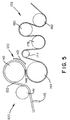
- a modified polyester roller assembly or apparatus system is generally indicated by the reference character 100 and is seen to comprise the zero-gap assembly 120 comprising upper and lower rollers 142 and 144, an entry bridle arrangement or system 132 comprising rollers 134, 136, 138 and 140, and an exit bridle arrangement or system 126 which comprises rollers 178, 180, 182, and 184.
- An idler roller 141 is interposed between roller 140 of the entry bridle system 132 and the upper roller 142 of the zero-gap roller assembly 120, and similarly, an idler roller 177 is interposed between the lower roller 144 or the zero-gap roller assembly 120 and the roller 178 of the exit bridle arrangement or system 126.
- the temperature of the sheet 122 must be maintained below the glass transition temperature (T g ) of approximately 80°C for any substantial period of time.
- polyester sheet 122 If the polyester sheet 122 is heated to a temperature level above the glass transition temperature (T g ) for any substantial period of time, the sheet 122 will crystallize, become sticky or tacky, and the sheet 122 will not be able to be properly conducted along its conveyance path through the entry bridle assembly 132 and the zero-gap roller assembly 120. Consequently, in accordance with the teachings of the present invention, all of the entry bridle assembly rollers 134, 136, 138 and 140, as well as the idler roller 141 and the upper roller 142 of the zero-gap roller assembly 120 are heated to and maintained at a temperature level of 75°C.
- T g glass transition temperature
- polyester sheet 122 In order to properly process the polyester sheet 122, that is, in order to obtain consistently oriented polyester sheeting which will, in turn, consistently exhibit the desired tensile strength, modulus, creep resistance, split resistance, and other characteristics or parameters, it is necessary to facilitate commencement of the orientation of the sheet workpiece 122 at a precise location along its conveyance path through the system. Since molecular orientation, and therefore crystallization, of the polyester sheeting occurs within the nip 146 defined between the upper and lower rollers 142, 144 of the zero-gap assembly 120, the most advantageous location at which the orientation can be commenced and controlled is at a location which immediately precedes the nip 146 defined between the rollers 142, 144.
- orientation of the sheet 122 would desirably be commenced within the lower right quadrant of such clock face, or in other words, anywhere within the range from the two o'clock position to the six o,clock position. It might be difficult to achieve such orientation commencement at the six o'clock position since such position comprises the location of the nip 146 defined between the rollers 142, 144, so consequently, it is preferred to commence orientation at a position which is effectively as close to the six o'clock position as is possible.
- infrared heaters 143 are disposed exteriorly of the upper roller 142 so as to heat the sheet workpiece 122. Such heating changes the tensile strength of the sheet workpiece 122 at such location, elongation of the sheet workpiece 122 becomes easier at such location, and consequently, orientation of the sheet workpiece 122 is controlled or forced to commence at such location.
- the infrared heaters 143 are disposed at, in effect, a five-thirty (5:30) clock face position, although they may be placed anywhere within the aforenoted range of two o'clock to five-thirty.
- the heaters 143 may have a length extending continuously from the two o'clock to five-thirty position so as to extend the heating region of the workpiece 122 depending upon the speed of the workpiece 122 through the assembly 120. While the infrared heaters 143 will raise the temperature of the workpiece 122 at such location to a temperature value which is greater than the glass transition temperature (T g ), due to the closeness of such location to the nip 146 defined between the upper and lower rollers 142 and 144, within which orientation-induced crystallization of the polyester sheet occurs, heat-induced crystallization is minimized.
- T g glass transition temperature
- a water-soluble, water-based emulsion comprising water, air, and 1-2% by weight oil, is applied as a spray, from spraying means 145, onto the lower surface of the sheet workpiece 122 at a conveyance position which is disposed upstream, for example, of the entry bridle idler roller 141.
- the lower surface of the sheet workpiece 122 becomes the inner surface with respect to the upper roller 142 of the zero-gap assembly 120, and consequently, such emulsion will present any sticking from occurring between the sheet workpiece 122 and the upper roller 142 of the zero-gap assembly 120.
- Sticking of the oriented sheet 122 upon the lower roller 144 of the zero-gap assembly 120 is not a problem because once the polyester sheet 122 undergoes its orientation within the nip 146 defined between the rollers 142 and 144 of the zero-gap assembly 120, the amorphous polyester is converted into crystalline polyester which does not exhibit sticky or tacky properties.
- the lower zero-gap roller 144 is rotated at a rotational speed such that the lineal surface velocity of such roller 144 is substantially greater than the rotational speed and effective lineal surface velocity of the upper zero-gap roller 142.
- the lineal surface velocity of the lower zero-gap roller 144 is set to be approximately 4-5 times that of the lineal surface velocity of the upper zero-gap roller 142 such that the draw ratio impressed upon the sheet workpiece is likewise within the range of 4-5:1.
- the exit bridle assembly rollers 178, 180, 182 and 184 are rotated at a rotational speed which is greater than that of the lower zero-gap roller 144 such that the lineal surface velocity, and therefore, the draw ratio, of the exit bridle assembly rollers 178, 180,182 and 184 are a multiple of the lineal surface velocity of the lower zero-gap roller 144.
- the present invention in accordance with the present invention.
- the lineal surface velocity of the exit bridle rollers 178, 180, 182 and 184 is set to be approximately l.l-1.5 times that of the lineal surface velocity of the lower zero-gap roller 144 such that the draw ratio impressed upon the sheet workpiece is likewise within the range of 1.1-1.5:1.
- the present invention comprises a two-step drawing process within an overall drawing ratio of approximately 6:1 being impressed upon the sheet workpiece 122.
- the lower zero-gap roller 144 is rotated at a rotational speed such that the lineal surface velocity thereof is 4.5 times the lineal surface velocity of the upper zero-gap roller 142, and the exit bridle rollers 178, 180, 182 and 184 are rotated at a rotational speed such that the lineal surface velocities thereof are 1.34 times the lineal surface velocity of the lower zero-gap roller 144, then an overall or resultant ratio of 6.03 would be achieved and impressed upon the sheet workpiece 122.
- the lineal surface velocity differential or drawing ratio between the lower zero-gap roller 144 and the upper zero-gap roller 142 could be 5.0 or 5:1, respectively, while the lineal surface velocity differential or drawing ratio defined between the exit bridle assembly rollers 178-184 and the lower zero-gap roller 144 could be 1.2 or 1.2:1, respectively, whereby, again, the overall drawing ratio would be 6:1.
- the lower zero-gap roller 144 is heated to a temperature level of 150°C while the exit bridle assembly rollers 178-184 may be maintained at room temperature (R T ).
- R T room temperature
- the resultant polyester sheeting exhibits tensile strength values of 1,000 psi (6.9 x 10 8 Pa) and modulus values of between 3,000,000 psi and 5,000,000 psi (2.1 x 10 10 to 3.5 x 10 10 Pa).
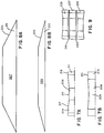
- FIGURES 7A and 7B there is shown, in effect, front view profiles of two differently contoured mill rollers which may be incorporated within the zero-gap assembly 120 of the system of FIGURES 5 and 6 in conjunction with the fabrication of the highly oriented polyester sheeting.
- the central portions of the rollers 204 and 206 are effectively concave as seen at 208 and 209, respectively, while the lateral side edge portions 1 and 213 have straight or horizontal configurations or contours.
- the edge portions of the sheet workpiece 122 will be worked to a greater degree than the central portions of the sheet workpiece 122 whereby the edge portions of the sheet workpiece 122 will be rendered thinner.
- the edge portions of the sheet workpiece 122 Upon being processed within the nip 146, the edge portions of the sheet workpiece 122 will also undergo thickening to some extent as described hereinbefore, whereby the finalized edge regions of the sheet workpiece 122 or finished sheet 122 will have the desired degree of thinness and uniformity of flatness as may be similarly achieved by means of the aforenoted edge and strip heating techniques.
- the primary difference between the contours or configurations of the mill rollers 204 and 206 resides in the fact that in the case of the roller 204 of FIGURE 7A, the central portion thereof has a cylindrical contour as at 215 while the adjacent axial portions thereof have tapered or frustoconical configurations as at 217. Finally, the outermost end or edge portions are cylindrical as at 219, the diametrical extent of cylindrical portions 219 being, however, greater than the diametrical extent of central cylindrical portion 215. Similarly, in the case of the roller 206 of FIGURE 7B, the central portion 209 has a concave arcuate configuration while the outermost end portions 221 are cylindrical and have diametrical extent which are greater than that of the central portion 209.
- FIGURE 8A, 8B and 9 another manufacturing technique which may be employed in order to achieve increased flatness or increased amounts of uniformly flat finished sheets across the width dimensions thereof involves the extrusion of the sheet workpiece 122 from particularly configured extrusion dies 223 and 225 which are respectively shown in FIGURES 8A and 8B.
- each one of the dies 223 and 225 has, in effect, a die mouth 227 and 229 which has a trapezoidal configuration which therefore produces polyester sheet workpiece 122 which likewise have trapezoidal cross-sectional configurations, or in other words, the edge portions 231 and 233 will be substantially thinner than the central portions of the sheet workpiece 122.
- a set of casting rollers 235, 237 and 239 are disclosed as being arranged in a vertical array.
- the upper and lower rollers 235 and 239 each have configurations which are somewhat similar to those of mill rollers 204 and 206, while the central casting roller 237 has a cylindrical configuration. Consequently, it can be appreciated that the spaces 241 and 243 defined respectively between the casting rollers 235 and 237 and 237 and 239, have, in effect, trapezoidal configurations such that when the sheet workpiece 122 is extruded from the die mouths 227 and 229, the workpiece 122 is initially routed about the casting rollers so as to be inserted into the space 241, wrapped around the roller 237, and withdrawn from the space 243.
- rollers 235 and 239 may be cylindrical while roller 237 has a configuration similar to that of roller 204 or 206. After passing through such spaces 241 and 243, the sheet workpiece 122 may be conveyed further toward the zero-gap assembly 120 for processing in accordance with the techniques of the present invention as previously described.
- finished milled and stretched sheet comprising highly-oriented polyester exhibit enhanced tensile strength and modulus characteristics.
- the sheets also exhibit improved degrees or uniformity of flatness whereby increased volumes of polyester strapping may be produced or derived therefrom.
Landscapes
- Engineering & Computer Science (AREA)
- Mechanical Engineering (AREA)
- Chemical & Material Sciences (AREA)
- Manufacturing & Machinery (AREA)
- Materials Engineering (AREA)
- Health & Medical Sciences (AREA)
- Chemical Kinetics & Catalysis (AREA)
- Medicinal Chemistry (AREA)
- Polymers & Plastics (AREA)
- Organic Chemistry (AREA)
- Shaping By String And By Release Of Stress In Plastics And The Like (AREA)
- Casting Or Compression Moulding Of Plastics Or The Like (AREA)
Applications Claiming Priority (2)
| Application Number | Priority Date | Filing Date | Title |
|---|---|---|---|
| US08/485,538 US5695709A (en) | 1992-10-09 | 1995-06-07 | Method and apparatus for producing highly oriented polyester sheet |
| US485538 | 1995-06-07 |
Publications (2)
| Publication Number | Publication Date |
|---|---|
| EP0747200A2 true EP0747200A2 (fr) | 1996-12-11 |
| EP0747200A3 EP0747200A3 (fr) | 1997-04-02 |
Family
ID=23928547
Family Applications (1)
| Application Number | Title | Priority Date | Filing Date |
|---|---|---|---|
| EP96303750A Withdrawn EP0747200A3 (fr) | 1995-06-07 | 1996-05-24 | Procédé pour la fabrication d'une feuille orientée en polyester |
Country Status (11)
| Country | Link |
|---|---|
| US (1) | US5695709A (fr) |
| EP (1) | EP0747200A3 (fr) |
| JP (1) | JPH08336891A (fr) |
| KR (1) | KR0185183B1 (fr) |
| CN (1) | CN1140653A (fr) |
| AU (1) | AU682634B2 (fr) |
| CA (1) | CA2176640A1 (fr) |
| IL (1) | IL118108A0 (fr) |
| NZ (1) | NZ286727A (fr) |
| TR (1) | TR199600409A2 (fr) |
| TW (1) | TW325435B (fr) |
Cited By (1)
| Publication number | Priority date | Publication date | Assignee | Title |
|---|---|---|---|---|
| EP1859916A4 (fr) * | 2005-03-15 | 2009-04-01 | Sekisui Chemical Co Ltd | Processus de production d une feuille de resine de polyester thermoplastique etiree et article moule et lamine |
Families Citing this family (16)
| Publication number | Priority date | Publication date | Assignee | Title |
|---|---|---|---|---|
| US5878901A (en) | 1997-02-21 | 1999-03-09 | Pharmagraphics (Midwest), L.L.C. | Composite hanger and label incorporating the same |
| US5985190A (en) | 1998-04-28 | 1999-11-16 | Genpak, L.L.C. | Method and system for forming low-density polymer foam article |
| US6630231B2 (en) * | 1999-02-05 | 2003-10-07 | 3M Innovative Properties Company | Composite articles reinforced with highly oriented microfibers |
| US6110588A (en) * | 1999-02-05 | 2000-08-29 | 3M Innovative Properties Company | Microfibers and method of making |
| AR027330A1 (es) * | 2000-02-09 | 2003-03-26 | Itw Mima Films Llc | Un metodo para fabricar pelicula estirada de plastico |
| KR100387216B1 (ko) * | 2001-03-19 | 2003-06-12 | 완 수 김 | 플라스틱 망상체 연신장치 |
| US6680114B2 (en) | 2001-05-15 | 2004-01-20 | 3M Innovative Properties Company | Fibrous films and articles from microlayer substrates |
| US7625628B2 (en) * | 2002-04-09 | 2009-12-01 | Illinois Tool Works Inc. | High integrity polyester strapping |
| US20050182233A1 (en) * | 2004-01-29 | 2005-08-18 | Stephen Weinhold | Compression-induced crystallization of crystallizable polymers |
| US7544318B2 (en) | 2004-04-05 | 2009-06-09 | Illinois Tool Works Inc. | Method and apparatus for producing oriented plastic strap |
| US7961430B2 (en) * | 2006-09-19 | 2011-06-14 | International Business Machines Corporation | Tape path control system with precision-aligned conjugated rollers |
| US8221109B2 (en) * | 2006-12-05 | 2012-07-17 | Gold Tip, Llc | Material layering device |
| US20080206381A1 (en) * | 2007-02-23 | 2008-08-28 | Nexcel Synthetics, Llc | Methods and systems for manufacturing yarns for synthetic turf |
| JP5162354B2 (ja) * | 2008-07-01 | 2013-03-13 | 積水化学工業株式会社 | 延伸熱可塑性ポリエステル系樹脂シートの製造方法 |
| KR101110375B1 (ko) * | 2009-07-20 | 2012-02-15 | 주식회사 메디칼써프라이 | 극초단파를 이용하는 의료기기용 멸균장치 |
| CN104772897A (zh) * | 2015-04-04 | 2015-07-15 | 江苏华尚汽车玻璃工业有限公司 | 一种汽车玻璃胶片快速成形设备 |
Family Cites Families (36)
| Publication number | Priority date | Publication date | Assignee | Title |
|---|---|---|---|---|
| US2326927A (en) * | 1938-01-15 | 1943-08-17 | Conrad Victor | Method of improving the grinding, mixing, and refining of rubber materials, synthetics, and plastics |
| US2471392A (en) * | 1946-09-25 | 1949-05-24 | Campbell Charles Herbert | Refining reclaimed rubber with cooling of the rubber to facilitate separation of tailings |
| US3083410A (en) * | 1956-11-23 | 1963-04-02 | Phillips Petroleum Co | Cold rolling film of high density ethylene polymer |
| GB980260A (en) * | 1960-05-19 | 1965-01-13 | Kodak Ltd | Improvements in the preparation of polyolefin sheeting |
| US3354023A (en) * | 1963-04-22 | 1967-11-21 | Du Pont | Oriented polymers |
| US3290420A (en) * | 1962-07-05 | 1966-12-06 | Columbian Rope Co | Process for making thin oriented plastic strips and tape |
| DE1277553B (de) * | 1963-07-09 | 1968-09-12 | Hench Hans | Vorrichtung und Verfahren zum fortlaufenden Laengsrecken von synthetischen Polymerfilmbahnen |
| US3394045A (en) * | 1964-07-27 | 1968-07-23 | Signode Corp | Polypropylene sheet and method |
| US3499957A (en) * | 1968-09-11 | 1970-03-10 | Union Carbide Corp | Method for producing substantially uniform calendered material |
| US3619460A (en) * | 1969-04-28 | 1971-11-09 | Chevron Res | Process for uniaxially orienting polypropylene films |
| US3651196A (en) * | 1969-07-29 | 1972-03-21 | Du Pont | Preparation of oriented polymeric strapping |
| US3741702A (en) * | 1970-03-14 | 1973-06-26 | C Mazzoni | Apparatus for pressure rolling soaps and similar products |
| FR2124227B1 (fr) * | 1971-02-01 | 1975-02-07 | Mambretti Giancarlo | |
| US3796785A (en) * | 1971-03-15 | 1974-03-12 | Bayer Ag | Method of stretching a thermoplastic sheet using a shortened stretching zone |
| US3800008A (en) * | 1971-08-05 | 1974-03-26 | Du Pont | Oriented polymer strap |
| JPS532668B2 (fr) * | 1974-04-30 | 1978-01-30 | ||
| US3956517A (en) * | 1974-05-13 | 1976-05-11 | The Procter & Gamble Company | Method of forming rippled chip-type products |
| GB1478576A (en) * | 1974-07-31 | 1977-07-06 | Nippon Petrochemicals Co Ltd | Method for the manufacture of rolled sheets and films of thermoplastic resins |
| DE2438983A1 (de) * | 1974-08-14 | 1976-03-04 | Berstorff Gmbh Masch Hermann | Mehrwalzenkalander zur herstellung von thermoplastischen folien |
| US4022863A (en) * | 1975-06-04 | 1977-05-10 | Caristrap Corporation | Polymer plastic strapping from polyethylene terephthalate |
| US4118454A (en) * | 1975-09-02 | 1978-10-03 | Sumitomo Bakelite Company Limited | Method for producing transparent plastic molded articles |
| FI64902C (fi) * | 1976-03-30 | 1984-02-10 | Wiik & Hoeglund | Foerfarande foer kompensering av valsboejningen i en kalander |
| US4101625A (en) * | 1977-01-10 | 1978-07-18 | Fmc Corporation | Method for making corrugated molecularly oriented plastic strapping |
| EP0030648B1 (fr) * | 1979-11-30 | 1984-03-07 | Sekisui Jushi Kabushiki Kaisha | Procédé pour la fabrication de matériau d'emballage en téréphtalate de polyéthylène |
| US4428720A (en) * | 1980-04-22 | 1984-01-31 | Signode Corporation | Apparatus for producing polypropylene sheet |
| US4495124A (en) * | 1980-04-22 | 1985-01-22 | Signode Corporation | Method for producing polypropylene sheet |
| US4311658A (en) * | 1980-05-02 | 1982-01-19 | Tenneco Chemicals, Inc. | Manufacture of continuous plastic sheets |
| US4408974A (en) * | 1982-01-20 | 1983-10-11 | Comerio Ercole, S.P.A. | Mobile film stretching unit |
| US4503007A (en) * | 1983-01-14 | 1985-03-05 | Tsukasa Kasei Kogyo Kabushiki Kaisha | Polypropylene strap and method of manufacturing the same |
| JPS60101032A (ja) * | 1983-11-08 | 1985-06-05 | Toyobo Co Ltd | 高強力高弾性率結晶性重合体延伸物の製造方法 |
| GB2161105B (en) * | 1984-07-04 | 1988-06-15 | Fred Whitehead | Calendar or roll assembly |
| US4849234A (en) * | 1984-11-13 | 1989-07-18 | Nabisco Brands, Inc. | Method of machining doughy material |
| US4681723A (en) * | 1985-11-01 | 1987-07-21 | American Hoechst Corporation | Calender band stripping section and process for stripping calendered sheet |
| US5049347A (en) * | 1988-11-22 | 1991-09-17 | The University Of Pittsburgh | Method for producing doubly oriented polymers |
| DE68925517T2 (de) * | 1988-11-16 | 1996-06-05 | Canon Kk | Verfahren zur Herstellung von Bildplatten |
| US5387388A (en) * | 1992-10-09 | 1995-02-07 | Illinois Tool Works Inc. | Method for producing oriented plastic strap |
-
1995
- 1995-06-07 US US08/485,538 patent/US5695709A/en not_active Expired - Fee Related
-
1996
- 1996-05-01 IL IL11810896A patent/IL118108A0/xx unknown
- 1996-05-08 TW TW085105438A patent/TW325435B/zh active
- 1996-05-15 CA CA002176640A patent/CA2176640A1/fr not_active Abandoned
- 1996-05-17 TR TR96/00409A patent/TR199600409A2/xx unknown
- 1996-05-24 EP EP96303750A patent/EP0747200A3/fr not_active Withdrawn
- 1996-05-28 CN CN96107869A patent/CN1140653A/zh active Pending
- 1996-06-05 NZ NZ286727A patent/NZ286727A/en unknown
- 1996-06-06 AU AU54754/96A patent/AU682634B2/en not_active Ceased
- 1996-06-07 JP JP8146190A patent/JPH08336891A/ja active Pending
- 1996-06-07 KR KR1019960020930A patent/KR0185183B1/ko not_active Expired - Fee Related
Cited By (2)
| Publication number | Priority date | Publication date | Assignee | Title |
|---|---|---|---|---|
| EP1859916A4 (fr) * | 2005-03-15 | 2009-04-01 | Sekisui Chemical Co Ltd | Processus de production d une feuille de resine de polyester thermoplastique etiree et article moule et lamine |
| US8617445B2 (en) | 2005-03-15 | 2013-12-31 | Sekisui Chemical Co., Ltd. | Process for producing oriented thermoplastic polyester resin sheet, and laminate-molded body |
Also Published As
| Publication number | Publication date |
|---|---|
| AU682634B2 (en) | 1997-10-09 |
| MX9602229A (es) | 1997-10-31 |
| CA2176640A1 (fr) | 1996-12-08 |
| KR0185183B1 (ko) | 1999-05-15 |
| TR199600409A2 (tr) | 1996-12-21 |
| NZ286727A (en) | 1998-04-27 |
| IL118108A0 (en) | 1996-09-12 |
| EP0747200A3 (fr) | 1997-04-02 |
| JPH08336891A (ja) | 1996-12-24 |
| KR970000508A (ko) | 1997-01-21 |
| CN1140653A (zh) | 1997-01-22 |
| AU5475496A (en) | 1996-12-19 |
| TW325435B (en) | 1998-01-21 |
| US5695709A (en) | 1997-12-09 |
Similar Documents
| Publication | Publication Date | Title |
|---|---|---|
| EP0747199B1 (fr) | Fabrication d'un ruban en plastique | |
| US5695709A (en) | Method and apparatus for producing highly oriented polyester sheet | |
| AU685722B2 (en) | Improvements to zero gap process | |
| EP0165255B1 (fr) | Procede et dispositif d'alimentation en bande thermoplastique en fusion | |
| US4428720A (en) | Apparatus for producing polypropylene sheet | |
| EP0591757B1 (fr) | Procédé et dispositif pour fabriquer des bandes orientées en matière plastiques | |
| US5707660A (en) | Apparatus for producing oriented plastic strap | |
| CN111873295B (zh) | 一种连续发泡材料的生产系统 | |
| EP0038559B1 (fr) | Procédé pour la fabrication d'une feuille résistant à l'abrasion et appareil pour sa fabrication | |
| US4495124A (en) | Method for producing polypropylene sheet | |
| US3635634A (en) | Apparatus for manufacturing tubular films of thermoplastic resins | |
| US3507135A (en) | Method and apparatus for forming thin metal belts | |
| WO1985002142A1 (fr) | Procede et dispositif d'alimentation en bande thermoplastique en fusion | |
| JPH059147Y2 (fr) | ||
| CN214522114U (zh) | 一种冷热辊薄膜定型装置 | |
| MXPA96002229A (es) | Metodo y aparato para producir una hoja de poliester altamente orientada | |
| JPH04246525A (ja) | 回転ロール式押出機におけるシート部材の押出方法 |
Legal Events
| Date | Code | Title | Description |
|---|---|---|---|
| PUAI | Public reference made under article 153(3) epc to a published international application that has entered the european phase |
Free format text: ORIGINAL CODE: 0009012 |
|
| AK | Designated contracting states |
Kind code of ref document: A2 Designated state(s): AT DE FR GB IT NL |
|
| PUAL | Search report despatched |
Free format text: ORIGINAL CODE: 0009013 |
|
| AK | Designated contracting states |
Kind code of ref document: A3 Designated state(s): AT DE FR GB IT NL |
|
| 17P | Request for examination filed |
Effective date: 19970926 |
|
| GRAG | Despatch of communication of intention to grant |
Free format text: ORIGINAL CODE: EPIDOS AGRA |
|
| 17Q | First examination report despatched |
Effective date: 19981216 |
|
| GRAG | Despatch of communication of intention to grant |
Free format text: ORIGINAL CODE: EPIDOS AGRA |
|
| GRAH | Despatch of communication of intention to grant a patent |
Free format text: ORIGINAL CODE: EPIDOS IGRA |
|
| STAA | Information on the status of an ep patent application or granted ep patent |
Free format text: STATUS: THE APPLICATION IS DEEMED TO BE WITHDRAWN |
|
| 18D | Application deemed to be withdrawn |
Effective date: 19991029 |