EP0747264A2 - Elektrischer Schalter mit rotierendem Mechanismus für Fahrzeuge - Google Patents
Elektrischer Schalter mit rotierendem Mechanismus für Fahrzeuge Download PDFInfo
- Publication number
- EP0747264A2 EP0747264A2 EP96303788A EP96303788A EP0747264A2 EP 0747264 A2 EP0747264 A2 EP 0747264A2 EP 96303788 A EP96303788 A EP 96303788A EP 96303788 A EP96303788 A EP 96303788A EP 0747264 A2 EP0747264 A2 EP 0747264A2
- Authority
- EP
- European Patent Office
- Prior art keywords
- carrier
- rotary
- housing
- rotary carrier
- finger
- Prior art date
- Legal status (The legal status is an assumption and is not a legal conclusion. Google has not performed a legal analysis and makes no representation as to the accuracy of the status listed.)
- Granted
Links
Images


Classifications
-
- B—PERFORMING OPERATIONS; TRANSPORTING
- B60—VEHICLES IN GENERAL
- B60Q—ARRANGEMENT OF SIGNALLING OR LIGHTING DEVICES, THE MOUNTING OR SUPPORTING THEREOF OR CIRCUITS THEREFOR, FOR VEHICLES IN GENERAL
- B60Q1/00—Arrangement of optical signalling or lighting devices, the mounting or supporting thereof or circuits therefor
- B60Q1/02—Arrangement of optical signalling or lighting devices, the mounting or supporting thereof or circuits therefor the devices being primarily intended to illuminate the way ahead or to illuminate other areas of way or environments
- B60Q1/04—Arrangement of optical signalling or lighting devices, the mounting or supporting thereof or circuits therefor the devices being primarily intended to illuminate the way ahead or to illuminate other areas of way or environments the devices being headlights
- B60Q1/14—Arrangement of optical signalling or lighting devices, the mounting or supporting thereof or circuits therefor the devices being primarily intended to illuminate the way ahead or to illuminate other areas of way or environments the devices being headlights having dimming means
- B60Q1/1446—Arrangement of optical signalling or lighting devices, the mounting or supporting thereof or circuits therefor the devices being primarily intended to illuminate the way ahead or to illuminate other areas of way or environments the devices being headlights having dimming means controlled by mechanically actuated switches
- B60Q1/1453—Hand actuated switches
- B60Q1/1461—Multifunction switches for dimming headlights and controlling additional devices, e.g. for controlling direction indicating lights
- B60Q1/1469—Multifunction switches for dimming headlights and controlling additional devices, e.g. for controlling direction indicating lights controlled by or attached to a single lever, e.g. steering column stalk switches
Definitions
- This invention relates generally to electrical switches and specifically to an electrical switch having a rotary mechanism for use in an automotive vehicle.
- rocker type switches for selectively conducting electrical current from a positive current electrically conductive terminal to a variety of other conductive terminals feeding window lift motors, interior reading lamps, radios or the like. It is also known to provide rocker switches having an internally mounted and spring biased plunger for selectively depressing against one or more portions of a fulcrummed contactor.
- a preferred embodiment of an electrical switch for use in an automotive vehicle includes a rotary carrier rotatable in response to engagement of a finger projecting from a movable main carrier.
- a detent structure is provided within a switch housing for engagement by a projection extending from the rotary carrier.
- the rotary carrier supports a conductive rotary contactor which is selectively actuable to conduct electrical current to a high beam headlamp conductive trace or a low beam headlamp conductive trace.
- Yet another aspect of the present invention provides a method for operating the electrical switch having a rotary mechanism.
- a channel is disposed between a plurality of conductive traces and the switch housing.
- the present invention is advantageous over conventional designs since the electrical switch of the present invention provides a cock-and-fire mechanism for achieving low travel actuation of an electrical switch such as a high beam/low beam headlamp dimmer switch. Furthermore, the high beam/low beam switch of the present invention also feels crisp upon actuation. Another advantage of the present invention is that minimal forces are required to actuate the switch due to the part geometries and cock-and-fire mechanism. The rotary mechanism further causes less electrical errosion of the conductive traces as compared to traditional linear contactor movement which causes excessive friction and travel as well as electrical arcing. The electrical switch of the present invention also achieves a more reliable electrical contact.
- the present invention can be easily preassembled without the traditional fear of the compression springs exploding components away from each other during assembly.
- the channels provide a receptacle for undesired debris created within most switches during electrical arcing; this allows for a cleaner contact surface between the rotary contactor and the conductive traces.
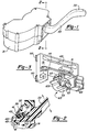
- a turn signal cancellation mechanism for use in an automotive vehicle is shown in Figures 1 and 2.
- This device includes a housing 31 mounted to a vehicle steering column and a turn signal handle 33 having a driver accessible end 35. Handle 33 is pivotable about the arrows shown in Figure 2 for operating a flash-to-pass headlamp feature and a high beam/low beam headlamp dimming switch feature.
- An actuator 37 is provided which contains a nominal detent position 39, a flash-to-pass detent position 41 and a high beam/low beam switching detent position 43.
- a spring biased plunger 45 within handle 33 engages with one of these detent positions.
- a driven end 47 of handle 33 is engagably received within a slot 49 within a main carrier 51.
- an electrical switch 61 of the present invention includes a rotary mechanism 63, a plurality of conductive traces 65, a finger 67, and a linear contactor 69, as well as housing 31 and main carrier 51.
- Main carrier 51 has a centrally positioned interior chamber 71 for receiving a cap 73 of finger 67.
- a preloaded clock spring 75 upwardly biases cap 73 against receptacle 71 of main carrier 51.
- Finger 67 further has an elongated lever 77 with a tip 79, a pair of shoulders 81 and a head 83.
- Head 83 movably rests along an internal shell 85 of cap 73 while a compression spring biases shoulders 81 of lever 77 away from a lower surface of cap 73.
- Compression spring 87 and clock spring 75 act to center finger 67 in relation to main carrier 51.
- the biased interaction between finger 67, a rotary carrier 101 and detent formations 307 and 309, defines the cock and fire mechanism.
- Return flanges of linear contactor 69 are movably received within a leg 89 of main carrier 51.
- a compression spring 91 is also located between leg 89 of main carrier 51 and a depressed center of linear contactor 69 for biasing linear contactor 69 away from main carrier 51 and toward various of the plurality of conductive traces 65.
- Main carrier 51 further has four lateral flanges 93 for slidably engaging within a pair of facing tracks 95 integrally molded within housing 31.
- Rotary mechanism 63 includes rotary carrier 101, a rotary contactor 103 and a projection or plunger 105.
- Rotary contactor 103 is secured to rotary carrier 101 for rotation therewith about a boss 107 integrally or separately attached to a segment 109 of housing 31.
- a pair of compression springs 111 serve to bias rotary contactor 103 away from rotary carrier 101 and toward various of the conductive traces 65.
- Rotary contactor 103 also has three raised contact points 113 extending from a nominal surface thereof.
- Plunger 105 is outwardly biased from within a groove 121 of rotary carrier 101 by a compression spring 123.
- Segment 109 can be integrally molded as part of the remainder of housing 31 or may be separately applied to the remainder of housing 31 by sonic welding, heat staking, snap fitting or the like after rotary mechanism 63 and main carrier 51 have been preassembled thereto. Preassembly of these switching components to segment 109 achieves a modularized unit thereby promoting easy access and vision during assembly so as to reduce assembly cost and scrap while improving placement, accuracy and quality.
- a supporting surface 151 of housing 31 has a pair of channels 153 integrally molded therein behind the plurality of conductive traces 65. This is illustrated in Figures 4 and 10-12. These channels 153 act to receive burned plastic, grease, metal oxides and other debris created during electrical arcing during switching and from the often dusty environment within which automotive vehicles are commonly used. These channels 153 aid in reducing debris build up between the contactors and conductive traces 65.
- Conductive traces 65 include a high beam headlamp stamping 181, a low beam headlamp stamping 183, a first positive current stamping 185 and a second positive current stamping 187. All of these stampings include substantially parallel electrical connector blades 189 for disengagably connecting to a wire harness electrical connector (not shown).
- conductive traces 65 terminate in a contact section 191 disposed in a co-planar manner along surface 151 of housing 31.
- the conductive traces do not extend along a bottom surface 193 of the switch receiving cavity of housing 31. This provides for more efficient trace packaging and lower part costs.
- Housing 31, rotary carrier 101, and main carrier 51 are all preferably injection molded from glass filled nylon such as DuPont Zytel® grade 70G30.
- Contactors 69 and 103 as well as conductive traces 67 are all preferably stamped from CA10194 copper.
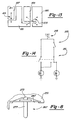
- finger 267 An alternate embodiment of finger 267 is shown in Figure 8.
- This finger embodiment employs a lever 277 integrally molded with cap 273.
- a leaf spring 287 has both ends captured within slots in a main carrier 251 and serves to center and retain finger 267 in relation to main carrier 251.
- the high beam/low beam dimmer switch function 211 is achieved by rotation of rotary contactor 103 between high beam stamping 181 and low beam stamping 183.
- Rotary contactor 103 is always in electrical contact with first positive current stamping 185 which is electrically connected to a headlamp on/off switch 213.
- a flash-to-pass switching function is achieved by linear movement of linear contactor 69 between second positive current stamping 187 and high beam headlamp stamping 181.
- a vehicle battery 215 is always feeding electrical current (B+) to second positive current stamping 187.
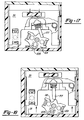
- Figure 15 illustrates main carrier 51 being moved toward rotary carrier 101 such that lever 77 has slid down a sloping surface 301, defined between a peak 303 and a first engagement surface 305 of rotary carrier 101.
- Rotary carrier 101 is shown disposed in a high beam rotated position such that plunger 105 engages a high beam detent formation 307.
- Figure 16 illustrates lever 77 pushing, and thereby rotating, rotary carrier 101 as main carrier 51 continues to move toward rotary carrier 101. Finger 67 is in its fully cocked position.
- main carrier 51 is shown fully moved toward rotary carrier 101 such that lever 77 is fully pivoted, or has been fired, and rotary carrier 101 has been moved to a low beam rotated position. In this position, plunger 105 has engaged a low beam detent formation 309 within housing 31.
- Figure 18 shows main carrier 51 moving away from rotary carrier 101 such that lever 77 is returned to its nominal central position. Returned linear movement of main carrier 51 toward rotary carrier 101 will subsequently engage lever 77 with an opposite engagement surface 311 for rotating rotary carrier 101 back to the rotated position shown in Figure 15. Lever 77 does not need to engage rotary carrier 101 when only the flash-to-pass function is being operated.
- the main carrier could pivot in relation to the housing as long as it serves to operate a rotary mechanism operable for switching between high beam and low beam modes.
- the disclosed cock and fire mechanism can be employed in a variety of other non-headlamp switches. Many other finger, contactor, carrier and conductive trace shapes and motions may be employed as long as the various aspects of the present invention are achieved.
- Various materials have been disclosed in an exemplary fashion, however, other materials may of course be employed. It is intended by the following claims to cover these and any other departures from the disclosed embodiments which fall within the true spirit of this invention.
Landscapes
- Engineering & Computer Science (AREA)
- Mechanical Engineering (AREA)
- Switches With Compound Operations (AREA)
- Rotary Switch, Piano Key Switch, And Lever Switch (AREA)
- Lighting Device Outwards From Vehicle And Optical Signal (AREA)
Applications Claiming Priority (2)
| Application Number | Priority Date | Filing Date | Title |
|---|---|---|---|
| US473570 | 1995-06-06 | ||
| US08/473,570 US5804782A (en) | 1995-06-06 | 1995-06-06 | Electrical switch having a rotary mechanism for use in an automotive vehicle |
Publications (3)
| Publication Number | Publication Date |
|---|---|
| EP0747264A2 true EP0747264A2 (de) | 1996-12-11 |
| EP0747264A3 EP0747264A3 (de) | 1997-11-05 |
| EP0747264B1 EP0747264B1 (de) | 2001-10-10 |
Family
ID=23880104
Family Applications (1)
| Application Number | Title | Priority Date | Filing Date |
|---|---|---|---|
| EP96303788A Expired - Lifetime EP0747264B1 (de) | 1995-06-06 | 1996-05-28 | Elektrischer Schalter mit rotierendem Mechanismus für Fahrzeuge |
Country Status (4)
| Country | Link |
|---|---|
| US (1) | US5804782A (de) |
| EP (1) | EP0747264B1 (de) |
| JP (1) | JPH09120755A (de) |
| DE (1) | DE69615750T2 (de) |
Families Citing this family (6)
| Publication number | Priority date | Publication date | Assignee | Title |
|---|---|---|---|---|
| FR2752962B1 (fr) * | 1996-09-03 | 1998-11-20 | Eaton Controls Sa | Systeme de transformation de mouvement |
| US5939683A (en) * | 1998-01-30 | 1999-08-17 | Eaton Corporation | High/low beam headlamps and fog lamps switch assembly |
| DE19912087A1 (de) * | 1999-03-18 | 2000-09-21 | Eaton Corp | Lenkstockschalter für Kraftfahrzeuge |
| JP2001067990A (ja) * | 1999-08-31 | 2001-03-16 | Yazaki Corp | レバースイッチの接点構造 |
| DE19958505C2 (de) * | 1999-12-04 | 2003-04-10 | Delphi Tech Inc | Lenkstockschalteranordnung |
| US6396011B1 (en) * | 2000-03-23 | 2002-05-28 | Valeo Electrical Systems, Inc. | Multi-function switch lever apparatus |
Family Cites Families (18)
| Publication number | Priority date | Publication date | Assignee | Title |
|---|---|---|---|---|
| US3586796A (en) * | 1969-02-14 | 1971-06-22 | American Plasticraft Co | Electrical switch with improved common terminal housing retaining means for pivoted contact |
| FR2246171A5 (de) * | 1973-09-28 | 1975-04-25 | Jaeger | |
| DE3038609C2 (de) * | 1980-10-13 | 1982-09-23 | Fa. Leopold Kostal, 5880 Lüdenscheid | Elektrischer Schalter |
| JPS61189523U (de) * | 1985-05-17 | 1986-11-26 | ||
| JPH0334814Y2 (de) * | 1985-05-17 | 1991-07-24 | ||
| US4695682A (en) * | 1985-12-23 | 1987-09-22 | United Technologies Automotive | Seat switch |
| JPS62121135U (de) * | 1985-12-23 | 1987-07-31 | ||
| JPH07108639B2 (ja) * | 1987-01-22 | 1995-11-22 | 日産自動車株式会社 | 車両用ヘッドランプの点灯制御装置 |
| DE3717251C2 (de) * | 1987-05-22 | 2001-10-04 | Teves Gmbh Alfred | Elektrischer Schalter, insbesondere Lenkstockschalter für Kraftfahrzeuge |
| JPH0735257Y2 (ja) * | 1988-03-18 | 1995-08-09 | 株式会社東海理化電機製作所 | スイッチ装置 |
| JPH01170043U (de) * | 1988-05-12 | 1989-11-30 | ||
| US4891475A (en) * | 1988-10-24 | 1990-01-02 | United Technologies Automotive, Inc. | Automotive beam selector switch system with flash-to-pass |
| JPH03219509A (ja) * | 1989-11-25 | 1991-09-26 | Seiko Epson Corp | スイッチ基板及びスイッチ基板製造方法 |
| US5049706A (en) * | 1990-05-25 | 1991-09-17 | Rocher Daniel J Du | Multifunction steering column switch |
| JP2565582Y2 (ja) * | 1990-07-18 | 1998-03-18 | 株式会社東海理化電機製作所 | レバースイッチ |
| JP2573191Y2 (ja) * | 1991-02-22 | 1998-05-28 | アルプス電気株式会社 | 揺動スイツチの可動接片支持構造 |
| JP2547127Y2 (ja) * | 1991-07-12 | 1997-09-10 | 株式会社東海理化電機製作所 | レバースイッチ装置 |
| US5385067A (en) * | 1993-09-13 | 1995-01-31 | United Technologies Automotive, Inc. | Turn signal cancellation mechanism |
-
1995
- 1995-06-06 US US08/473,570 patent/US5804782A/en not_active Expired - Fee Related
-
1996
- 1996-05-28 EP EP96303788A patent/EP0747264B1/de not_active Expired - Lifetime
- 1996-05-28 DE DE69615750T patent/DE69615750T2/de not_active Expired - Fee Related
- 1996-06-06 JP JP8143807A patent/JPH09120755A/ja active Pending
Also Published As
| Publication number | Publication date |
|---|---|
| US5804782A (en) | 1998-09-08 |
| DE69615750T2 (de) | 2002-07-11 |
| EP0747264B1 (de) | 2001-10-10 |
| JPH09120755A (ja) | 1997-05-06 |
| EP0747264A3 (de) | 1997-11-05 |
| DE69615750D1 (de) | 2001-11-15 |
Similar Documents
| Publication | Publication Date | Title |
|---|---|---|
| JP2779951B2 (ja) | インデックスロータリースイッチ | |
| US5149924A (en) | Multiple contact switch arrangement | |
| US5491311A (en) | Multifunction switch | |
| JP3108011B2 (ja) | パワーウィンドの運動を制御するための装置 | |
| EP0807033B1 (de) | Rückstellungseinrichtung für fahrrichtungsanzeige | |
| JP2003151403A (ja) | スイッチ | |
| US5804782A (en) | Electrical switch having a rotary mechanism for use in an automotive vehicle | |
| US5651450A (en) | Switches, in particular switches that can be installed into the instrument panel of a vehicle, and a method for manufacturing a switch | |
| US4357511A (en) | Modular push-button switch with lighted push-button element | |
| US6512191B1 (en) | Push-switch and method for manufacturing the same | |
| US5821490A (en) | Push button switch module | |
| US5041703A (en) | Mirror control switch for automotive vehicles | |
| JP3769873B2 (ja) | トリガースイッチ | |
| US5107085A (en) | Clustered push button switches having sheet metal conductors formed with contact tabs | |
| US5111011A (en) | Mirror control slide switch for automotive vehicles | |
| CN212380387U (zh) | 一种汽车多功能方向盘开关总成 | |
| RU2121185C1 (ru) | Многофункциональный выключатель, преимущественно выключатель для регулирования положения зеркала автомобиля | |
| US5860516A (en) | Electric switch assembly | |
| US5981886A (en) | Multifunction switch assembly | |
| US3721779A (en) | Sliding action electrical switch with ramp portions between contacts and insulating strips | |
| JP4196080B2 (ja) | 車両用プッシュスイッチ | |
| JP3638196B2 (ja) | プッシュスイッチ | |
| US20080067049A1 (en) | Light assembly for vehicle interiors | |
| US6559400B2 (en) | Switch structure for car electrical part | |
| US7005592B2 (en) | Plunger contact assembly for an automobile control stalk |
Legal Events
| Date | Code | Title | Description |
|---|---|---|---|
| PUAI | Public reference made under article 153(3) epc to a published international application that has entered the european phase |
Free format text: ORIGINAL CODE: 0009012 |
|
| AK | Designated contracting states |
Kind code of ref document: A2 Designated state(s): DE ES FR GB IT |
|
| PUAL | Search report despatched |
Free format text: ORIGINAL CODE: 0009013 |
|
| AK | Designated contracting states |
Kind code of ref document: A3 Designated state(s): DE ES FR GB IT |
|
| 17P | Request for examination filed |
Effective date: 19980130 |
|
| RAP1 | Party data changed (applicant data changed or rights of an application transferred) |
Owner name: UT AUTOMOTIVE DEARBORN, INC. |
|
| 17Q | First examination report despatched |
Effective date: 19990526 |
|
| RAP1 | Party data changed (applicant data changed or rights of an application transferred) |
Owner name: LEAR AUTOMOTIVE DEARBORN, INC. |
|
| GRAG | Despatch of communication of intention to grant |
Free format text: ORIGINAL CODE: EPIDOS AGRA |
|
| GRAG | Despatch of communication of intention to grant |
Free format text: ORIGINAL CODE: EPIDOS AGRA |
|
| GRAH | Despatch of communication of intention to grant a patent |
Free format text: ORIGINAL CODE: EPIDOS IGRA |
|
| GRAH | Despatch of communication of intention to grant a patent |
Free format text: ORIGINAL CODE: EPIDOS IGRA |
|
| GRAA | (expected) grant |
Free format text: ORIGINAL CODE: 0009210 |
|
| AK | Designated contracting states |
Kind code of ref document: B1 Designated state(s): DE ES FR GB IT |
|
| PG25 | Lapsed in a contracting state [announced via postgrant information from national office to epo] |
Ref country code: IT Free format text: LAPSE BECAUSE OF FAILURE TO SUBMIT A TRANSLATION OF THE DESCRIPTION OR TO PAY THE FEE WITHIN THE PRESCRIBED TIME-LIMIT;WARNING: LAPSES OF ITALIAN PATENTS WITH EFFECTIVE DATE BEFORE 2007 MAY HAVE OCCURRED AT ANY TIME BEFORE 2007. THE CORRECT EFFECTIVE DATE MAY BE DIFFERENT FROM THE ONE RECORDED. Effective date: 20011010 Ref country code: FR Free format text: LAPSE BECAUSE OF FAILURE TO SUBMIT A TRANSLATION OF THE DESCRIPTION OR TO PAY THE FEE WITHIN THE PRESCRIBED TIME-LIMIT Effective date: 20011010 |
|
| REF | Corresponds to: |
Ref document number: 69615750 Country of ref document: DE Date of ref document: 20011115 |
|
| REG | Reference to a national code |
Ref country code: GB Ref legal event code: IF02 |
|
| PG25 | Lapsed in a contracting state [announced via postgrant information from national office to epo] |
Ref country code: ES Free format text: LAPSE BECAUSE OF FAILURE TO SUBMIT A TRANSLATION OF THE DESCRIPTION OR TO PAY THE FEE WITHIN THE PRESCRIBED TIME-LIMIT Effective date: 20020430 |
|
| PG25 | Lapsed in a contracting state [announced via postgrant information from national office to epo] |
Ref country code: GB Free format text: LAPSE BECAUSE OF NON-PAYMENT OF DUE FEES Effective date: 20020528 |
|
| EN | Fr: translation not filed | ||
| PLBE | No opposition filed within time limit |
Free format text: ORIGINAL CODE: 0009261 |
|
| STAA | Information on the status of an ep patent application or granted ep patent |
Free format text: STATUS: NO OPPOSITION FILED WITHIN TIME LIMIT |
|
| 26N | No opposition filed | ||
| GBPC | Gb: european patent ceased through non-payment of renewal fee |
Effective date: 20020528 |
|
| PGFP | Annual fee paid to national office [announced via postgrant information from national office to epo] |
Ref country code: DE Payment date: 20060630 Year of fee payment: 11 |
|
| PG25 | Lapsed in a contracting state [announced via postgrant information from national office to epo] |
Ref country code: DE Free format text: LAPSE BECAUSE OF NON-PAYMENT OF DUE FEES Effective date: 20071201 |