EP0747582A2 - Elément de découplage pour les vibrations dans les conduits - Google Patents
Elément de découplage pour les vibrations dans les conduits Download PDFInfo
- Publication number
- EP0747582A2 EP0747582A2 EP96108162A EP96108162A EP0747582A2 EP 0747582 A2 EP0747582 A2 EP 0747582A2 EP 96108162 A EP96108162 A EP 96108162A EP 96108162 A EP96108162 A EP 96108162A EP 0747582 A2 EP0747582 A2 EP 0747582A2
- Authority
- EP
- European Patent Office
- Prior art keywords
- housing
- pipe connection
- spring
- decoupling element
- element according
- Prior art date
- Legal status (The legal status is an assumption and is not a legal conclusion. Google has not performed a legal analysis and makes no representation as to the accuracy of the status listed.)
- Granted
Links
Images


Classifications
-
- F—MECHANICAL ENGINEERING; LIGHTING; HEATING; WEAPONS; BLASTING
- F01—MACHINES OR ENGINES IN GENERAL; ENGINE PLANTS IN GENERAL; STEAM ENGINES
- F01N—GAS-FLOW SILENCERS OR EXHAUST APPARATUS FOR MACHINES OR ENGINES IN GENERAL; GAS-FLOW SILENCERS OR EXHAUST APPARATUS FOR INTERNAL-COMBUSTION ENGINES
- F01N13/00—Exhaust or silencing apparatus characterised by constructional features
- F01N13/18—Construction facilitating manufacture, assembly, or disassembly
- F01N13/1805—Fixing exhaust manifolds, exhaust pipes or pipe sections to each other, to engine or to vehicle body
- F01N13/1811—Fixing exhaust manifolds, exhaust pipes or pipe sections to each other, to engine or to vehicle body with means permitting relative movement, e.g. compensation of thermal expansion or vibration
- F01N13/1816—Fixing exhaust manifolds, exhaust pipes or pipe sections to each other, to engine or to vehicle body with means permitting relative movement, e.g. compensation of thermal expansion or vibration the pipe sections being joined together by flexible tubular elements only, e.g. using bellows or strip-wound pipes
-
- F—MECHANICAL ENGINEERING; LIGHTING; HEATING; WEAPONS; BLASTING
- F16—ENGINEERING ELEMENTS AND UNITS; GENERAL MEASURES FOR PRODUCING AND MAINTAINING EFFECTIVE FUNCTIONING OF MACHINES OR INSTALLATIONS; THERMAL INSULATION IN GENERAL
- F16L—PIPES; JOINTS OR FITTINGS FOR PIPES; SUPPORTS FOR PIPES, CABLES OR PROTECTIVE TUBING; MEANS FOR THERMAL INSULATION IN GENERAL
- F16L27/00—Adjustable joints; Joints allowing movement
- F16L27/10—Adjustable joints; Joints allowing movement comprising a flexible connection only
- F16L27/107—Adjustable joints; Joints allowing movement comprising a flexible connection only the ends of the pipe being interconnected by a flexible sleeve
- F16L27/11—Adjustable joints; Joints allowing movement comprising a flexible connection only the ends of the pipe being interconnected by a flexible sleeve the sleeve having the form of a bellows with multiple corrugations
-
- F—MECHANICAL ENGINEERING; LIGHTING; HEATING; WEAPONS; BLASTING
- F16—ENGINEERING ELEMENTS AND UNITS; GENERAL MEASURES FOR PRODUCING AND MAINTAINING EFFECTIVE FUNCTIONING OF MACHINES OR INSTALLATIONS; THERMAL INSULATION IN GENERAL
- F16L—PIPES; JOINTS OR FITTINGS FOR PIPES; SUPPORTS FOR PIPES, CABLES OR PROTECTIVE TUBING; MEANS FOR THERMAL INSULATION IN GENERAL
- F16L51/00—Expansion-compensation arrangements for pipe-lines
- F16L51/02—Expansion-compensation arrangements for pipe-lines making use of a bellows or an expansible folded or corrugated tube
- F16L51/025—Expansion-compensation arrangements for pipe-lines making use of a bellows or an expansible folded or corrugated tube with several corrugations
Definitions
- the invention relates to a decoupling element for vibrations in pipes, in particular for installation in exhaust systems of internal combustion engines.
- a known decoupling element (DE-A-44 01 827) comprises a housing made of two housing halves which are connected to one another by a folded cable element which projects radially over the outer circumference of the housing.
- the end of the housing is rigidly connected, for example by welding, to the pipe connection pieces of the flexible bellows connecting element.
- the axial or angular flexibility of the housing is achieved in that areas of the housing halves have a resilient property and the folded cable element supports this property.
- a decoupling element (EP-A-0 615 595) in which the End parts of a two-part housing are welded to the respective pipe connection pieces and are connected to a permanent arrangement by a coil spring surrounding the bellows connecting element.
- a decoupling element Common to the known solutions is that they are not suitable for creating a decoupling element with a tubular, essentially smooth-cylindrical outer configuration, as is generally desired for reasons of assembly, storage and space requirements.
- the known decoupling elements have a complicated structure due to the multi-part nature of the housing and the measures that create the axial and angular flexibility, so that a high manufacturing effort with corresponding costs is required.
- the invention has for its object to provide a decoupling element of the type mentioned, with which one or more of the aforementioned disadvantages of known decoupling elements are avoided.
- the invention is intended to provide an essentially torsionally rigid decoupling element with minimal structural dimensions, which is readily available in a smooth-cylindrical, e.g. tubular configuration and can be mass-produced with comparatively few manufacturing steps.
- Further objects of the invention are: Creation of a decoupling element of the aforementioned type with overload protection by means of a progressive spring characteristic under tensile and compressive stress; lateral deflection stiffness despite possible compensation of installation tolerances; suitable bending softness, which can take into account motor pitch movements.
- the decoupling element according to the invention is characterized by the features of patent claim 1.
- the housing is then in a known manner in the area of at least one of its axial ends, but preferably both ends, not rigidly connected to the adjacent pipe connection piece, but connected via an articulated spring arrangement which gives the decoupling element the axial and angular flexibility.
- the housing can therefore be formed in one piece, stiff and smooth-cylindrical without any protruding parts on the outside, since the measures creating the flexibility are shifted into the area of the front ends of the decoupling element.
- Each spring element of the articulated spring arrangement represents a continuous ring element which is arranged essentially concentrically to the relevant pipe connection piece and which is connected alternately circumferentially to the housing or the pipe connection piece, the connection points being circumferentially offset from one another.
- the intermediate areas between the connection points create the desired resilience without requiring an increased space.
- the arrangement of the spring elements facilitates the manufacture and assembly of the decoupling element, the spring elements, due to their structure, being able to be easily manufactured in our own factories with little manufacturing outlay, if desired.
- the hinge spring arrangement can also be easily adapted to the loads and desired specifications, for example by providing several concentric ring spring elements.
- the ring spring elements can advantageously be designed as disc spring elements.
- Disc spring elements of this type are fundamentally torsionally rigid and are therefore suitable for effectively protecting the bellows-type connecting element from damaging torsional stresses.
- an articulated spring arrangement can be a good one Have flexibility.
- the fundamentally progressive spring characteristic of disc spring elements is particularly advantageous. This means that the design of the articulated spring arrangement can be such that there is a desired softness in the normal operating range, while with increasing deflection the articulated spring arrangement becomes stiffer due to the progressive spring characteristic, which ensures that harmful deformations are avoided under high loads and also offers advantages with regard to the vibration behavior of the decoupling element , because there is a low risk of resonance.
- Several disc spring elements can be combined to form a spring package, which creates a good vibration-damping effect due to the friction between the individual disc spring elements. This makes it possible to dispense with additional measures for damping the vibrations in the form of damping inserts.
- the forces between the pipe connection pieces and the housing are advantageously transmitted via three-point connections, so that the resultant force lies on the central longitudinal axis of the decoupling element and does not cause any bending moment.
- An exhaust system equipped with a decoupling element according to the invention is therefore reliably supported.
- the housing can have a smooth, closed design on the outside, the parts accommodated therein, such as the bellows-type connecting element and, if appropriate, an additional damping element arranged thereon, are effectively protected against external environmental influences.
- the housing arrangement can be open at the end, so that the parts accommodated therein be effectively ventilated, which offers protection against corrosion.
- the housing arrangement can also be of lightweight construction without significant loss of rigidity, for example by large openings are provided.
- the spring element can also be formed from a wire rope material as a ring element arranged concentrically with the pipe connection piece in question.
- a spring element can easily be provided within the housing, which enables dimensions of the decoupling element that do not differ significantly from so-called flexible hoses, as are often used in exhaust systems.
- the spring characteristic of such an articulated spring arrangement is essentially symmetrical in the case of tensile and compressive stresses, but is progressive, which at the same time means effective protection against overload with good vibration decoupling behavior under normal operating conditions.
- the hinge spring arrangement of these alternatives of the invention is also torsionally rigid; it therefore protects the bellows connection element against damaging torsional stresses.
- Wire rope spring elements can be prefabricated and assembled as a single unit. It can further be provided that the articulated spring arrangement is shielded from the outside by a radial region of the housing. This creates an effective axial path limitation that protects the bellows connecting element and the wire rope spring element against excessive deflections during assembly or during transport. At the same time, the parts inside the housing are protected from damage, such as stone chipping, and the acoustic behavior of the decoupling element improved compared to an arrangement with an open-ended housing.
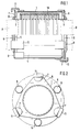
- a common feature of the decoupling elements according to the invention is a bellows-like corrugated continuous connecting element 1 made of a suitable material such as metal, at the axial ends of which a cylindrical pipe connection piece 2, 3 is formed.
- the pipe fittings 2, 3 can be an integral part of the connecting element 1 or z. B. be fixed by welding. They are used to connect the decoupling element to the ends of pipes indicated by dashed lines at A and B, e.g. the exhaust pipe of an internal combustion engine.
- a housing 4 is arranged concentrically to the central longitudinal axis thereof, which surrounds the connecting element 1 on the outside and with its axial end regions can protrude somewhat on both sides over the axial ends of the connecting element 1.
- the housing 3 can have the shape of a rigid, circular cylindrical, smooth outer tube section. However, the invention is not limited to such a configuration of the housing 4, which will be discussed in more detail later.
- a damping insert 10 in the form of a knitted metal wire knitting with the connecting element 1 on the outside be provided in the space between the connecting element 1 and the housing 4.
- the circumferential layers of the holder-side connection points 7 and the housing-side connection points 6 are offset from one another, so that in each case a housing-side connection point 6 comes to lie between a pair of holder-side connection points 7.
- free sections of the disk spring element 5 remain between adjacent connection points 6, 7 on the housing and holder, which enable a limited axial and angular relative movement between the relevant pipe connection piece 2 or 3 and the housing 4 in the manner of a joint.
- the articulated spring arrangements cooperate at both axial ends of the housing 4 in order to additionally enable radial displacement of the central longitudinal axes of the pipe connection pieces 2, 3.
- connection points 6, 7 are provided for the connection points 6, 7 on the housing and holder side intended. It goes without saying that other suitable joining techniques can also be used, for example spot welding, spot bonding, or clamping or screw connections. Furthermore, the number of the respective housing or bracket-side connection points 6, 7 is not limited to the number three. Rather, more or fewer such connection points could also be provided, with the increasing number of connection points increasing the resistance which the disc spring element 5 opposes to an axial or angular relative movement between the housing 4 and the pipe connection pieces 2, 3.
- the distribution of the housing and bracket-side connection points along the circumference of the disc spring element 5 can be non-uniform, as a result of which the stiffness of the disc spring element 5 becomes different along its circumference and a decoupling element with direction-dependent axial and angular compliance can be obtained.
- travel limiters 11 can also be provided in the area of the axial ends of the housing 4, which, with their hook-shaped sections, encompass the disc spring element 5 on the outside in order to limit the axial and angular relative movement between the housing 4 and the disc spring element 5 and in this way a To prevent overloading the hinge spring arrangement.
- the articulated spring arrangement comprises a single annular disc spring element 5. If desired, however, a plurality of disc spring elements 5 can also be arranged one behind the other, for example in the form of a spring assembly, whereby the spring stiffness of the articulated spring arrangement can be changed or influenced accordingly. Such an arrangement has good vibration damping properties due to friction between the individual disc spring elements 5.
- a plurality of disc spring elements 5 or spring assemblies can be arranged concentrically one behind the other at a distance from one another by providing spacers between the disc spring elements 5 or the spring assemblies, which causes a corresponding increase in the spring travel.
- the disc spring member 5 also need not necessarily have a circular configuration. Rather, it can also have a polygonal annular configuration or, if appropriate, be composed of individual rectilinear sections to form an annular shape.
- each disk spring element could also be corrugated in order to create a distance from the adjacent disk spring element.
- FIG. 3 shows a further embodiment of the invention, which essentially differs from the embodiment described above and shown in FIGS. 1 and 2 in that the housing 4 is provided with a plurality of circumferentially distributed openings for saving weight, on which the damping insert 10 exposed to the outside.
- the limiters are omitted.
- the third embodiment of the invention shown in FIG. 4 differs from the first embodiment in that the housing 4 only has an axial end in the region of its one, namely preferably downstream, end Articulated spring arrangement of the type described above is connected to the relevant pipe connection piece 2, while in the region of its other axial end, as indicated at 12, it can be angled in the direction of the relevant pipe connection piece 3 and thus directly welded.
- the third embodiment of the invention only provides axial and angular flexibility, but no radial displacement possibility of the central longitudinal axes of the pipe connection pieces 2, 3.
- an embodiment of the invention is shown with an articulated spring arrangement which, instead of an annular disc spring element, comprises an annular spring element 15 made of a metallic wire rope material, which continuously surrounds the relevant pipe connection piece 3 in the region of the one axial end of the housing 4 and analogously to the disc spring element of the above-described embodiments is connected to the housing 4 or the pipe connection piece 3 at locations or regions 16, 17 which are offset circumferentially from one another.
- the punctiform connection can take place in the form of a welded connection or preferably by means of pipe sockets encompassing the spring element 15, which can be fastened to the housing 4 or pipe connection piece 2, for example welded on or formed from sections of these components by reshaping.
- connection points 16, 17 could be provided, it is preferred that a pair of connection points on the housing and pipe connection side is provided in diametrically opposite relationship.
- annular wire rope spring element 15 can be completely accommodated within the outline of the housing 4 and can thus be effectively protected against external influences such as stone chipping. If desired, two or more annular wire rope spring elements 15 can be provided one behind the other with appropriate reinforcement of the spring characteristic.
- the housing 4, as indicated at 19, can have an extension which is bent radially in the direction of the downstream pipe connection piece 2 and which essentially axially adjusts the space between the housing 4 and the pipe connection piece 2 with the joint spring arrangement accommodated therein shields outside. At the same time, this creates effective sound shielding and path limitation.
- a tubular heat protection element 20 which extends from the upstream pipe connection piece 3 coaxially to the central longitudinal axis of the decoupling element over a suitable distance along the length of the pipe connecting element 1, has the task of preventing the pipe connecting element 1 from overheating. It goes without saying that such a heat protection element 20 can, if desired, also be omitted and also added to the embodiments of the invention shown in FIGS. 1-5 with disk spring joint arrangements.
- the hinge spring arrangements of all the above-described embodiments of the invention are basically torsionally rigid. They are therefore preferably used with bellows-like corrugated connecting elements 1, in which the corrugations lie in a radial plane, so that the connecting element 1 is also fundamentally torsion-resistant.
- the torsionally rigid design of the articulated spring arrangements means that the bellows-like connecting element 1 is effectively protected against overload.
Landscapes
- Engineering & Computer Science (AREA)
- General Engineering & Computer Science (AREA)
- Mechanical Engineering (AREA)
- Chemical & Material Sciences (AREA)
- Combustion & Propulsion (AREA)
- Exhaust Silencers (AREA)
- Joints Allowing Movement (AREA)
- Pipe Accessories (AREA)
- Vibration Prevention Devices (AREA)
- Rigid Pipes And Flexible Pipes (AREA)
Applications Claiming Priority (2)
| Application Number | Priority Date | Filing Date | Title |
|---|---|---|---|
| DE29509434U | 1995-06-08 | ||
| DE29509434U DE29509434U1 (de) | 1995-06-08 | 1995-06-08 | Entkopplungselement für Schwingungen in Rohrleitungen |
Publications (4)
| Publication Number | Publication Date |
|---|---|
| EP0747582A2 true EP0747582A2 (fr) | 1996-12-11 |
| EP0747582A3 EP0747582A3 (fr) | 1997-06-25 |
| EP0747582B1 EP0747582B1 (fr) | 1998-07-15 |
| EP0747582B2 EP0747582B2 (fr) | 2003-08-27 |
Family
ID=8009106
Family Applications (1)
| Application Number | Title | Priority Date | Filing Date |
|---|---|---|---|
| EP96108162A Expired - Lifetime EP0747582B2 (fr) | 1995-06-08 | 1996-05-22 | Elément de découplage pour les vibrations dans les conduits |
Country Status (3)
| Country | Link |
|---|---|
| US (1) | US5797628A (fr) |
| EP (1) | EP0747582B2 (fr) |
| DE (2) | DE29509434U1 (fr) |
Cited By (4)
| Publication number | Priority date | Publication date | Assignee | Title |
|---|---|---|---|---|
| EP1674685A1 (fr) * | 2004-12-27 | 2006-06-28 | Burgmann Industries GmbH & Co. KG | Elément de raccordement pour raccorder des extrémités de deux tuyaux d'une façon non-rigide |
| EP2042702A1 (fr) * | 2007-09-27 | 2009-04-01 | Witzenmann GmbH | Dispositif d'amortissement |
| EP2042701A1 (fr) * | 2007-09-27 | 2009-04-01 | Witzenmann GmbH | Dispositif d'amortissement |
| WO2024104741A1 (fr) * | 2022-11-17 | 2024-05-23 | Eagleburgmann Germany Gmbh & Co. Kg | Dispositif de compensation |
Families Citing this family (12)
| Publication number | Priority date | Publication date | Assignee | Title |
|---|---|---|---|---|
| DE19706191A1 (de) * | 1997-02-18 | 1998-08-20 | Witzenmann Metallschlauchfab | Gelenkiges Verbindungselement für Rohrteile |
| KR100281630B1 (ko) * | 1998-01-20 | 2001-02-15 | 김용호 | 자동차 배기관용 디커플러 |
| ES2178096T3 (es) * | 1998-12-03 | 2002-12-16 | Burgmann Dichtungswerke Gmbh | Elemento de desacoplamiento para vibraciones en tuberias, en especial instalaciones de escape de gases. |
| KR100353123B1 (ko) * | 2000-08-28 | 2002-09-16 | 주식회사 에스제이엠 | 자동차 배기관용 연결구 |
| US20040092463A1 (en) * | 2002-11-11 | 2004-05-13 | Isis Pharmaceuticals Inc. | Modulation of PIM-1 expression |
| KR100602770B1 (ko) * | 2004-07-20 | 2006-07-20 | 주식회사 에스제이엠 | 자동차 배기관용 플렉시블 튜브 |
| US20060197340A1 (en) * | 2005-03-03 | 2006-09-07 | Katayama Kogyo Co., Ltd. | Flexible joint for exhaust pipe |
| KR100735940B1 (ko) * | 2005-06-15 | 2007-07-06 | 주식회사 에스제이엠 | 자동차 배기관용 플렉시블 튜브 |
| US8033576B2 (en) * | 2007-10-12 | 2011-10-11 | Flex-Hose Co. Inc. | Pipe guide for expansion joint |
| DE102012204800A1 (de) * | 2012-03-26 | 2013-09-26 | Krones Ag | Rohrleitungsverbinder mit Kompensator |
| US20160069491A1 (en) * | 2014-09-09 | 2016-03-10 | The Metraflex Company | Self-adjusting piping system for allowing and absorbing seismic movements of pipelines |
| DE202016101495U1 (de) * | 2016-03-17 | 2017-06-20 | Krones Aktiengesellschaft | Pulsationsdämpfer |
Family Cites Families (32)
| Publication number | Priority date | Publication date | Assignee | Title |
|---|---|---|---|---|
| US3084957A (en) * | 1963-04-09 | Bellows conduit coupling with strain relief cable | ||
| DE895847C (de) * | 1942-08-29 | 1953-11-05 | Metallgummi G M B H | Elastische Rohrverbindung |
| GB627120A (en) * | 1948-01-23 | 1949-07-28 | Kac Ltd | Improvements in or relating to flexible couplings for pipes and the like |
| GB695015A (en) * | 1950-02-01 | 1953-08-05 | Power Jets Res & Dev Ltd | Improvements in flexible couplings for pipes and the like |
| US3019037A (en) * | 1959-05-21 | 1962-01-30 | Joseph M Caldwell | Universally flexible conduit joint |
| DE1450409A1 (de) * | 1964-04-23 | 1969-05-22 | Siemens Ag | Kompensator fuer Druckmittelleitungen,insbesondere Luft- und Gasleitungen grossen Durchmessers |
| FR1428758A (fr) * | 1965-03-18 | 1966-02-18 | Power Aux Ies Ltd | Joint universel pour tubes |
| US3369829A (en) * | 1965-10-15 | 1968-02-20 | William C.N. Hopkins | Flexible connector for fluid conduit systems |
| ES425973A1 (es) * | 1973-05-23 | 1976-09-16 | Citroen Sa | Dispositivo de union de dos conductos de fluido. |
| DE2703064A1 (de) * | 1977-01-26 | 1978-07-27 | Krupp Gmbh | Kompensator fuer rohr- o.dgl. leitungen, und dessen verwendung |
| DE2714830C3 (de) * | 1977-04-02 | 1979-10-11 | J.M. Voith Gmbh, 7920 Heidenheim | Rohrverbindung für Riserstränge |
| DE7908868U1 (de) * | 1979-03-29 | 1979-07-19 | Metallschlauch-Fabrik Pforzheim (Vorm. Hch. Witzenmann) Gmbh, 7530 Pforzheim | Anordnung zur elastischen verbindung zweier heissgehender rohrleitungen, insbesondere von auspuffleitungen von kraftfahrzeugen |
| US4659117A (en) * | 1982-08-10 | 1987-04-21 | Iwk Regler Und Kompensatoren Gmbh | Flexible coupling for pipes in exhaust systems of motor vehicles |
| DE8222490U1 (de) * | 1982-08-10 | 1982-11-11 | IWK Regler und Kompensatoren GmbH, 7513 Stutensee | Einrichtung zum gelenkigen verbinden von motor und abgasanlage |
| EP0208128B1 (fr) * | 1985-07-12 | 1990-02-07 | Witzenmann GmbH Metallschlauch-Fabrik Pforzheim | Connexion articulée d'éléments de tube, notamment dans des conduits d'échappement de véhicules automobiles |
| US4746148A (en) * | 1987-02-27 | 1988-05-24 | Flexonics Inc. | Limiting structure for axial expansion joint |
| FR2625546B1 (fr) * | 1988-01-05 | 1990-03-09 | Acc Jonchere Sa | Joint rotulaire |
| EP0453691A1 (fr) * | 1989-03-14 | 1991-10-30 | A C C La Jonchere | Joint rotulaire |
| FR2645939B1 (fr) * | 1989-04-18 | 1991-06-21 | Tubest Sa | Moyens de raccordement articule pour tuyaux |
| DE3915838A1 (de) * | 1989-05-16 | 1990-11-22 | Witzenmann Metallschlauchfab | Verbindung zweier rohre einer leitung fuer heisse medien |
| DE4034055A1 (de) * | 1989-11-09 | 1991-05-16 | Witzenmann Metallschlauchfab | Flexibles leitungselement fuer abgasleitungen von verbrennungsmotoren bei kraftfahrzeugen |
| US5069487A (en) * | 1990-02-08 | 1991-12-03 | Flexonics Inc. | Flexible connector |
| US5133578A (en) * | 1991-03-08 | 1992-07-28 | Ltv Energy Products Company | Flexible joint with non-diffusive barrier |
| EP0519636B1 (fr) * | 1991-06-14 | 1995-10-18 | Toyota Jidosha Kabushiki Kaisha | Raccord flexible pour un tuyau d'échappement |
| FR2684052B1 (fr) * | 1991-11-22 | 1997-05-30 | Ecia Equip Composants Ind Auto | Dispositif pour relier par articulation des organes d'une ligne d'echappement, notamment d'un vehicule automobile. |
| DE4233644C2 (de) * | 1992-10-06 | 1994-08-18 | Burgmann Dichtungswerk Feodor | Flexible Verbindungsanordnung für zwei Rohrteile, insbesondere bei Abgasanlagen von Kraftfahrzeugen |
| US5354104A (en) * | 1993-01-15 | 1994-10-11 | Techlam | Flexible coupling for pipework |
| DE4401827C3 (de) * | 1993-02-06 | 2003-06-18 | Iwka Balg Und Kompensatoren Te | Vorrichtung zur gelenkigen Verbindung von Rohren einer Abgasanlage |
| FR2701753B1 (fr) * | 1993-02-19 | 1995-05-24 | Ecia Equip Composants Ind Auto | Dispositif pour relier par articulation des organes d'une ligne d'échappement, notamment pour véhicule automobile. |
| DE4317334C2 (de) * | 1993-05-25 | 2003-09-25 | Iwka Balg Und Kompensatoren Te | Vorrichtung zum flexiblen Verbinden von Rohren in Abgasleitungen von Kraftfahrzeugen |
| DE4317333C2 (de) * | 1993-05-25 | 1995-06-08 | Iwk Regler Kompensatoren | Vorrichtung zum Dämpfen von Schwingungen in Abgasleitungen von Kraftfahrzeugen |
| DE4444550A1 (de) * | 1994-12-14 | 1996-06-27 | Daimler Benz Ag | Vorrichtung zur Verbindung von zwei rohrförmigen Leitungsteilen |
-
1995
- 1995-06-08 DE DE29509434U patent/DE29509434U1/de not_active Expired - Lifetime
-
1996
- 1996-05-22 DE DE59600338T patent/DE59600338D1/de not_active Expired - Lifetime
- 1996-05-22 EP EP96108162A patent/EP0747582B2/fr not_active Expired - Lifetime
- 1996-06-03 US US08/657,305 patent/US5797628A/en not_active Expired - Fee Related
Cited By (4)
| Publication number | Priority date | Publication date | Assignee | Title |
|---|---|---|---|---|
| EP1674685A1 (fr) * | 2004-12-27 | 2006-06-28 | Burgmann Industries GmbH & Co. KG | Elément de raccordement pour raccorder des extrémités de deux tuyaux d'une façon non-rigide |
| EP2042702A1 (fr) * | 2007-09-27 | 2009-04-01 | Witzenmann GmbH | Dispositif d'amortissement |
| EP2042701A1 (fr) * | 2007-09-27 | 2009-04-01 | Witzenmann GmbH | Dispositif d'amortissement |
| WO2024104741A1 (fr) * | 2022-11-17 | 2024-05-23 | Eagleburgmann Germany Gmbh & Co. Kg | Dispositif de compensation |
Also Published As
| Publication number | Publication date |
|---|---|
| DE59600338D1 (de) | 1998-08-20 |
| EP0747582B2 (fr) | 2003-08-27 |
| US5797628A (en) | 1998-08-25 |
| EP0747582A3 (fr) | 1997-06-25 |
| DE29509434U1 (de) | 1996-08-01 |
| EP0747582B1 (fr) | 1998-07-15 |
Similar Documents
| Publication | Publication Date | Title |
|---|---|---|
| EP0797039B1 (fr) | Elément de tuyau avec soufflet métallique | |
| EP0208128B1 (fr) | Connexion articulée d'éléments de tube, notamment dans des conduits d'échappement de véhicules automobiles | |
| EP0856648B1 (fr) | Elément de conduite flexible pour conduites de gaz d'échappement | |
| EP0747582A2 (fr) | Elément de découplage pour les vibrations dans les conduits | |
| DE29907590U1 (de) | Abkoppelelement zur Abkopplung von Schwingungen | |
| DE3610684A1 (de) | Gelenkige verbindung von rohrteilen, insbesondere bei abgasleitungen von kraftfahrzeugen | |
| DE19709403A1 (de) | Flexible Verbindung | |
| DE19706191A1 (de) | Gelenkiges Verbindungselement für Rohrteile | |
| EP0681097B1 (fr) | Elément de connexion flexible pour éléments tubulaires | |
| DE19641963C1 (de) | Leitungselement mit einem Balg aus Metall | |
| EP0398086B1 (fr) | Raccordement pour deux tuyaux d'un conduit pour médium chaud | |
| EP0573764B1 (fr) | Joint articulé d'éléments de tube, notamment dans des conduits d'échappement de véhicules automobiles | |
| EP0816738B1 (fr) | Dispositif de découplement pour vibrations dans conduits | |
| DE102013106075B4 (de) | Vorrichtung zum schwingungsentkoppelten Verbinden zweier Einrichtungen einer Abgasanlage | |
| EP0709558B1 (fr) | Elément de conduit pour la conduite des gaz d'échappement d'un moteur à combustion interne | |
| EP1026376A2 (fr) | Joint flexible pour découplage de vibrations | |
| EP0295444B1 (fr) | Connexion de deux tuyaux d'une conduite pour fluides chauds | |
| DE102013210982A1 (de) | Dehnkörper zur Verbindung von zwei Rohrstücken insbesondere eines Abgaskanals eines Kraftfahrzeugs sowie Abgasturboladereinheit mit einem derartigen Dehnkörper | |
| EP0750100B1 (fr) | Elément de conduite flexible pour tuyaux d'échappement de véhicules | |
| EP0903528B1 (fr) | Elément de tuyau avec soufflet métallique | |
| EP1531242B1 (fr) | Elément de découplage pour systèmes d'échappement | |
| EP1674685A1 (fr) | Elément de raccordement pour raccorder des extrémités de deux tuyaux d'une façon non-rigide | |
| DE102004025946B4 (de) | Leitungselement | |
| DE3524931A1 (de) | Gelenkige verbindung von rohrteilen, insbesondere bei abgasleitungen von kraftfahrzeugen | |
| DE19642010A1 (de) | Flexible Verbindungsanordnung zum Anschluß eines Rohres einer Abgasanlage, insbesondere eines Kraftfahrzeuges, an einen Motor |
Legal Events
| Date | Code | Title | Description |
|---|---|---|---|
| PUAI | Public reference made under article 153(3) epc to a published international application that has entered the european phase |
Free format text: ORIGINAL CODE: 0009012 |
|
| AK | Designated contracting states |
Kind code of ref document: A2 Designated state(s): DE ES FR GB IT NL SE |
|
| PUAL | Search report despatched |
Free format text: ORIGINAL CODE: 0009013 |
|
| AK | Designated contracting states |
Kind code of ref document: A3 Designated state(s): DE ES FR GB IT NL SE |
|
| 17P | Request for examination filed |
Effective date: 19970527 |
|
| 17Q | First examination report despatched |
Effective date: 19970814 |
|
| GRAG | Despatch of communication of intention to grant |
Free format text: ORIGINAL CODE: EPIDOS AGRA |
|
| GRAG | Despatch of communication of intention to grant |
Free format text: ORIGINAL CODE: EPIDOS AGRA |
|
| GRAH | Despatch of communication of intention to grant a patent |
Free format text: ORIGINAL CODE: EPIDOS IGRA |
|
| GRAH | Despatch of communication of intention to grant a patent |
Free format text: ORIGINAL CODE: EPIDOS IGRA |
|
| GRAA | (expected) grant |
Free format text: ORIGINAL CODE: 0009210 |
|
| AK | Designated contracting states |
Kind code of ref document: B1 Designated state(s): DE ES FR GB IT NL SE |
|
| PG25 | Lapsed in a contracting state [announced via postgrant information from national office to epo] |
Ref country code: NL Free format text: LAPSE BECAUSE OF FAILURE TO SUBMIT A TRANSLATION OF THE DESCRIPTION OR TO PAY THE FEE WITHIN THE PRESCRIBED TIME-LIMIT Effective date: 19980715 Ref country code: IT Free format text: LAPSE BECAUSE OF FAILURE TO SUBMIT A TRANSLATION OF THE DESCRIPTION OR TO PAY THE FEE WITHIN THE PRESCRIBED TIME-LIMIT;WARNING: LAPSES OF ITALIAN PATENTS WITH EFFECTIVE DATE BEFORE 2007 MAY HAVE OCCURRED AT ANY TIME BEFORE 2007. THE CORRECT EFFECTIVE DATE MAY BE DIFFERENT FROM THE ONE RECORDED. Effective date: 19980715 |
|
| REF | Corresponds to: |
Ref document number: 59600338 Country of ref document: DE Date of ref document: 19980820 |
|
| GBT | Gb: translation of ep patent filed (gb section 77(6)(a)/1977) |
Effective date: 19980731 |
|
| ET | Fr: translation filed | ||
| NLV1 | Nl: lapsed or annulled due to failure to fulfill the requirements of art. 29p and 29m of the patents act | ||
| PLBQ | Unpublished change to opponent data |
Free format text: ORIGINAL CODE: EPIDOS OPPO |
|
| PLBI | Opposition filed |
Free format text: ORIGINAL CODE: 0009260 |
|
| 26 | Opposition filed |
Opponent name: IWK REGLER + KOMPENSATOREN GMBH Effective date: 19990310 |
|
| PLBF | Reply of patent proprietor to notice(s) of opposition |
Free format text: ORIGINAL CODE: EPIDOS OBSO |
|
| PG25 | Lapsed in a contracting state [announced via postgrant information from national office to epo] |
Ref country code: ES Free format text: THE PATENT HAS BEEN ANNULLED BY A DECISION OF A NATIONAL AUTHORITY Effective date: 19990523 |
|
| PLBF | Reply of patent proprietor to notice(s) of opposition |
Free format text: ORIGINAL CODE: EPIDOS OBSO |
|
| RAP2 | Party data changed (patent owner data changed or rights of a patent transferred) |
Owner name: BURGMANN DICHTUNGSWERKE GMBH & CO. KG |
|
| PLBO | Opposition rejected |
Free format text: ORIGINAL CODE: EPIDOS REJO |
|
| APAC | Appeal dossier modified |
Free format text: ORIGINAL CODE: EPIDOS NOAPO |
|
| APAE | Appeal reference modified |
Free format text: ORIGINAL CODE: EPIDOS REFNO |
|
| APAC | Appeal dossier modified |
Free format text: ORIGINAL CODE: EPIDOS NOAPO |
|
| REG | Reference to a national code |
Ref country code: GB Ref legal event code: IF02 |
|
| APAC | Appeal dossier modified |
Free format text: ORIGINAL CODE: EPIDOS NOAPO |
|
| PLAW | Interlocutory decision in opposition |
Free format text: ORIGINAL CODE: EPIDOS IDOP |
|
| PUAH | Patent maintained in amended form |
Free format text: ORIGINAL CODE: 0009272 |
|
| STAA | Information on the status of an ep patent application or granted ep patent |
Free format text: STATUS: PATENT MAINTAINED AS AMENDED |
|
| 27A | Patent maintained in amended form |
Effective date: 20030827 |
|
| AK | Designated contracting states |
Designated state(s): DE ES FR GB IT NL SE |
|
| GBTA | Gb: translation of amended ep patent filed (gb section 77(6)(b)/1977) | ||
| REG | Reference to a national code |
Ref country code: SE Ref legal event code: RPEO |
|
| ET3 | Fr: translation filed ** decision concerning opposition | ||
| REG | Reference to a national code |
Ref country code: ES Ref legal event code: FD2A Effective date: 20000610 |
|
| APAH | Appeal reference modified |
Free format text: ORIGINAL CODE: EPIDOSCREFNO |
|
| REG | Reference to a national code |
Ref country code: GB Ref legal event code: 732E |
|
| REG | Reference to a national code |
Ref country code: FR Ref legal event code: TP Ref country code: FR Ref legal event code: CD |
|
| PGFP | Annual fee paid to national office [announced via postgrant information from national office to epo] |
Ref country code: SE Payment date: 20060524 Year of fee payment: 11 |
|
| EUG | Se: european patent has lapsed | ||
| PG25 | Lapsed in a contracting state [announced via postgrant information from national office to epo] |
Ref country code: SE Free format text: LAPSE BECAUSE OF NON-PAYMENT OF DUE FEES Effective date: 20070523 |
|
| PLAB | Opposition data, opponent's data or that of the opponent's representative modified |
Free format text: ORIGINAL CODE: 0009299OPPO |
|
| PGFP | Annual fee paid to national office [announced via postgrant information from national office to epo] |
Ref country code: FR Payment date: 20100608 Year of fee payment: 15 |
|
| PGFP | Annual fee paid to national office [announced via postgrant information from national office to epo] |
Ref country code: DE Payment date: 20100525 Year of fee payment: 15 |
|
| PGFP | Annual fee paid to national office [announced via postgrant information from national office to epo] |
Ref country code: GB Payment date: 20100521 Year of fee payment: 15 |
|
| REG | Reference to a national code |
Ref country code: GB Ref legal event code: 732E Free format text: REGISTERED BETWEEN 20101223 AND 20101229 |
|
| REG | Reference to a national code |
Ref country code: DE Ref legal event code: R119 Ref document number: 59600338 Country of ref document: DE |
|
| REG | Reference to a national code |
Ref country code: DE Ref legal event code: R119 Ref document number: 59600338 Country of ref document: DE |
|
| GBPC | Gb: european patent ceased through non-payment of renewal fee |
Effective date: 20110522 |
|
| REG | Reference to a national code |
Ref country code: FR Ref legal event code: ST Effective date: 20120131 |
|
| PG25 | Lapsed in a contracting state [announced via postgrant information from national office to epo] |
Ref country code: FR Free format text: LAPSE BECAUSE OF NON-PAYMENT OF DUE FEES Effective date: 20110531 |
|
| PG25 | Lapsed in a contracting state [announced via postgrant information from national office to epo] |
Ref country code: GB Free format text: LAPSE BECAUSE OF NON-PAYMENT OF DUE FEES Effective date: 20110522 |
|
| PG25 | Lapsed in a contracting state [announced via postgrant information from national office to epo] |
Ref country code: DE Free format text: LAPSE BECAUSE OF NON-PAYMENT OF DUE FEES Effective date: 20111130 |