EP0747587B1 - Einrichtung zur Einstellung der Rohrlänge von Saugrohren und Verfahren zu deren Herstellung - Google Patents
Einrichtung zur Einstellung der Rohrlänge von Saugrohren und Verfahren zu deren Herstellung Download PDFInfo
- Publication number
- EP0747587B1 EP0747587B1 EP96105400A EP96105400A EP0747587B1 EP 0747587 B1 EP0747587 B1 EP 0747587B1 EP 96105400 A EP96105400 A EP 96105400A EP 96105400 A EP96105400 A EP 96105400A EP 0747587 B1 EP0747587 B1 EP 0747587B1
- Authority
- EP
- European Patent Office
- Prior art keywords
- guide ring
- control flap
- intake system
- intake
- pipe
- Prior art date
- Legal status (The legal status is an assumption and is not a legal conclusion. Google has not performed a legal analysis and makes no representation as to the accuracy of the status listed.)
- Expired - Lifetime
Links
- 238000004519 manufacturing process Methods 0.000 title description 8
- 238000000034 method Methods 0.000 title description 2
- 229910052751 metal Inorganic materials 0.000 claims description 24
- 239000002184 metal Substances 0.000 claims description 24
- 230000008878 coupling Effects 0.000 claims description 13
- 238000010168 coupling process Methods 0.000 claims description 13
- 238000005859 coupling reaction Methods 0.000 claims description 13
- 239000004952 Polyamide Substances 0.000 claims description 12
- 229920002647 polyamide Polymers 0.000 claims description 12
- 239000000654 additive Substances 0.000 claims description 11
- 230000000996 additive effect Effects 0.000 claims description 11
- 239000003365 glass fiber Substances 0.000 claims description 11
- 238000002485 combustion reaction Methods 0.000 claims description 8
- 239000004033 plastic Substances 0.000 claims description 8
- 238000013461 design Methods 0.000 claims description 5
- 230000003014 reinforcing effect Effects 0.000 claims description 4
- 239000000463 material Substances 0.000 description 12
- 238000002347 injection Methods 0.000 description 4
- 239000007924 injection Substances 0.000 description 4
- 238000001746 injection moulding Methods 0.000 description 3
- CWQXQMHSOZUFJS-UHFFFAOYSA-N molybdenum disulfide Chemical compound S=[Mo]=S CWQXQMHSOZUFJS-UHFFFAOYSA-N 0.000 description 3
- 230000015572 biosynthetic process Effects 0.000 description 2
- 238000010276 construction Methods 0.000 description 2
- 101001017827 Mus musculus Leucine-rich repeat flightless-interacting protein 1 Proteins 0.000 description 1
- 238000013459 approach Methods 0.000 description 1
- 238000011161 development Methods 0.000 description 1
- 230000018109 developmental process Effects 0.000 description 1
- 239000000446 fuel Substances 0.000 description 1
- 238000003780 insertion Methods 0.000 description 1
- 230000037431 insertion Effects 0.000 description 1
- 235000015095 lager Nutrition 0.000 description 1
- 239000000203 mixture Substances 0.000 description 1
- 239000002990 reinforced plastic Substances 0.000 description 1
- 239000011227 reinforcement additive Substances 0.000 description 1
- 238000012549 training Methods 0.000 description 1
- 230000007704 transition Effects 0.000 description 1
Images
Classifications
-
- B—PERFORMING OPERATIONS; TRANSPORTING
- B29—WORKING OF PLASTICS; WORKING OF SUBSTANCES IN A PLASTIC STATE IN GENERAL
- B29C—SHAPING OR JOINING OF PLASTICS; SHAPING OF MATERIAL IN A PLASTIC STATE, NOT OTHERWISE PROVIDED FOR; AFTER-TREATMENT OF THE SHAPED PRODUCTS, e.g. REPAIRING
- B29C45/00—Injection moulding, i.e. forcing the required volume of moulding material through a nozzle into a closed mould; Apparatus therefor
- B29C45/0017—Injection moulding, i.e. forcing the required volume of moulding material through a nozzle into a closed mould; Apparatus therefor moulding interconnected elements which are movable with respect to one another, e.g. chains or hinges
-
- F—MECHANICAL ENGINEERING; LIGHTING; HEATING; WEAPONS; BLASTING
- F02—COMBUSTION ENGINES; HOT-GAS OR COMBUSTION-PRODUCT ENGINE PLANTS
- F02B—INTERNAL-COMBUSTION PISTON ENGINES; COMBUSTION ENGINES IN GENERAL
- F02B27/00—Use of kinetic or wave energy of charge in induction systems, or of combustion residues in exhaust systems, for improving quantity of charge or for increasing removal of combustion residues
- F02B27/02—Use of kinetic or wave energy of charge in induction systems, or of combustion residues in exhaust systems, for improving quantity of charge or for increasing removal of combustion residues the systems having variable, i.e. adjustable, cross-sectional areas, chambers of variable volume, or like variable means
- F02B27/0205—Use of kinetic or wave energy of charge in induction systems, or of combustion residues in exhaust systems, for improving quantity of charge or for increasing removal of combustion residues the systems having variable, i.e. adjustable, cross-sectional areas, chambers of variable volume, or like variable means characterised by the charging effect
- F02B27/0215—Oscillating pipe charging, i.e. variable intake pipe length charging
-
- F—MECHANICAL ENGINEERING; LIGHTING; HEATING; WEAPONS; BLASTING
- F02—COMBUSTION ENGINES; HOT-GAS OR COMBUSTION-PRODUCT ENGINE PLANTS
- F02B—INTERNAL-COMBUSTION PISTON ENGINES; COMBUSTION ENGINES IN GENERAL
- F02B27/00—Use of kinetic or wave energy of charge in induction systems, or of combustion residues in exhaust systems, for improving quantity of charge or for increasing removal of combustion residues
- F02B27/02—Use of kinetic or wave energy of charge in induction systems, or of combustion residues in exhaust systems, for improving quantity of charge or for increasing removal of combustion residues the systems having variable, i.e. adjustable, cross-sectional areas, chambers of variable volume, or like variable means
- F02B27/0226—Use of kinetic or wave energy of charge in induction systems, or of combustion residues in exhaust systems, for improving quantity of charge or for increasing removal of combustion residues the systems having variable, i.e. adjustable, cross-sectional areas, chambers of variable volume, or like variable means characterised by the means generating the charging effect
- F02B27/0247—Plenum chambers; Resonance chambers or resonance pipes
- F02B27/0263—Plenum chambers; Resonance chambers or resonance pipes the plenum chamber and at least one of the intake ducts having a common wall, and the intake ducts wrap partially around the plenum chamber, i.e. snail-type
-
- F—MECHANICAL ENGINEERING; LIGHTING; HEATING; WEAPONS; BLASTING
- F02—COMBUSTION ENGINES; HOT-GAS OR COMBUSTION-PRODUCT ENGINE PLANTS
- F02B—INTERNAL-COMBUSTION PISTON ENGINES; COMBUSTION ENGINES IN GENERAL
- F02B27/00—Use of kinetic or wave energy of charge in induction systems, or of combustion residues in exhaust systems, for improving quantity of charge or for increasing removal of combustion residues
- F02B27/02—Use of kinetic or wave energy of charge in induction systems, or of combustion residues in exhaust systems, for improving quantity of charge or for increasing removal of combustion residues the systems having variable, i.e. adjustable, cross-sectional areas, chambers of variable volume, or like variable means
- F02B27/0226—Use of kinetic or wave energy of charge in induction systems, or of combustion residues in exhaust systems, for improving quantity of charge or for increasing removal of combustion residues the systems having variable, i.e. adjustable, cross-sectional areas, chambers of variable volume, or like variable means characterised by the means generating the charging effect
- F02B27/0268—Valves
- F02B27/0273—Flap valves
-
- F—MECHANICAL ENGINEERING; LIGHTING; HEATING; WEAPONS; BLASTING
- F02—COMBUSTION ENGINES; HOT-GAS OR COMBUSTION-PRODUCT ENGINE PLANTS
- F02D—CONTROLLING COMBUSTION ENGINES
- F02D9/00—Controlling engines by throttling air or fuel-and-air induction conduits or exhaust conduits
- F02D9/08—Throttle valves specially adapted therefor; Arrangements of such valves in conduits
- F02D9/10—Throttle valves specially adapted therefor; Arrangements of such valves in conduits having pivotally-mounted flaps
- F02D9/1035—Details of the valve housing
- F02D9/106—Sealing of the valve shaft in the housing, e.g. details of the bearings
-
- F—MECHANICAL ENGINEERING; LIGHTING; HEATING; WEAPONS; BLASTING
- F16—ENGINEERING ELEMENTS AND UNITS; GENERAL MEASURES FOR PRODUCING AND MAINTAINING EFFECTIVE FUNCTIONING OF MACHINES OR INSTALLATIONS; THERMAL INSULATION IN GENERAL
- F16K—VALVES; TAPS; COCKS; ACTUATING-FLOATS; DEVICES FOR VENTING OR AERATING
- F16K27/00—Construction of housing; Use of materials therefor
- F16K27/02—Construction of housing; Use of materials therefor of lift valves
- F16K27/0209—Check valves or pivoted valves
- F16K27/0218—Butterfly valves
-
- B—PERFORMING OPERATIONS; TRANSPORTING
- B29—WORKING OF PLASTICS; WORKING OF SUBSTANCES IN A PLASTIC STATE IN GENERAL
- B29C—SHAPING OR JOINING OF PLASTICS; SHAPING OF MATERIAL IN A PLASTIC STATE, NOT OTHERWISE PROVIDED FOR; AFTER-TREATMENT OF THE SHAPED PRODUCTS, e.g. REPAIRING
- B29C45/00—Injection moulding, i.e. forcing the required volume of moulding material through a nozzle into a closed mould; Apparatus therefor
- B29C45/16—Making multilayered or multicoloured articles
- B29C45/1671—Making multilayered or multicoloured articles with an insert
-
- B—PERFORMING OPERATIONS; TRANSPORTING
- B29—WORKING OF PLASTICS; WORKING OF SUBSTANCES IN A PLASTIC STATE IN GENERAL
- B29L—INDEXING SCHEME ASSOCIATED WITH SUBCLASS B29C, RELATING TO PARTICULAR ARTICLES
- B29L2031/00—Other particular articles
- B29L2031/748—Machines or parts thereof not otherwise provided for
- B29L2031/7506—Valves
-
- F—MECHANICAL ENGINEERING; LIGHTING; HEATING; WEAPONS; BLASTING
- F02—COMBUSTION ENGINES; HOT-GAS OR COMBUSTION-PRODUCT ENGINE PLANTS
- F02D—CONTROLLING COMBUSTION ENGINES
- F02D9/00—Controlling engines by throttling air or fuel-and-air induction conduits or exhaust conduits
- F02D9/08—Throttle valves specially adapted therefor; Arrangements of such valves in conduits
- F02D9/10—Throttle valves specially adapted therefor; Arrangements of such valves in conduits having pivotally-mounted flaps
- F02D9/107—Manufacturing or mounting details
-
- Y—GENERAL TAGGING OF NEW TECHNOLOGICAL DEVELOPMENTS; GENERAL TAGGING OF CROSS-SECTIONAL TECHNOLOGIES SPANNING OVER SEVERAL SECTIONS OF THE IPC; TECHNICAL SUBJECTS COVERED BY FORMER USPC CROSS-REFERENCE ART COLLECTIONS [XRACs] AND DIGESTS
- Y02—TECHNOLOGIES OR APPLICATIONS FOR MITIGATION OR ADAPTATION AGAINST CLIMATE CHANGE
- Y02T—CLIMATE CHANGE MITIGATION TECHNOLOGIES RELATED TO TRANSPORTATION
- Y02T10/00—Road transport of goods or passengers
- Y02T10/10—Internal combustion engine [ICE] based vehicles
- Y02T10/12—Improving ICE efficiencies
Definitions
- the invention relates to a suction system for internal combustion engines according to the preamble of claim 1.
- suction systems according to the prior art known in which an intake manifold by means of a control valve in length in at least two different lengths is adjustable.
- a suction pipe is usually used arranged in a spiral. Located in the center of the spiral an air chamber with an air inlet opening for the Air supply.
- a tube is spirally around this chamber wound around, the end of it on a cylinder an internal combustion engine is connected.
- About one Breakthrough in the side wall of the air chamber can occur Part of the pipe length can be bridged.
- a control flap is usually arranged by means of which the breakthrough can be opened or closed. about this control flap can thus be the active length of the Adjust the suction pipe in two stages, which makes a better one Torque curve of the internal combustion engine can be achieved can.
- suction systems are generally used in multi-cylinder injection engines used, has one Suction system several suction pipes arranged side by side are and supplied with air via a common suction line become.
- control flap is usually in a guide ring rotatably mounted in the edge of said breakthrough the side wall of the air chamber closes.
- the control flap too and the guide ring are already partly in metal, partly made in plastic.
- the object of the invention is therefore to propose a suction system, in which the parts are assembled with little effort can.
- the guide ring and the suction system Control valve formed as a unit in which the Guide ring is made in one piece and to the Control flap two substantially opposite each other Bearing journals are formed, which penetrate the guide ring.
- the entire guide ring and Control flap existing unit without additional Work steps are installed in the suction system.
- Farther is due to the described design of the guide ring and Control flap the control flap captive in the Guide ring held.
- the bearing journal is recommended to be attached to the bearing journal in each case form an annular shoulder, by means of which the control flap is fixed in the direction mentioned.
- At least one operating lever is on integrally formed on a bearing journal outside of the guide ring to operate the control flaps.
- a lever is attached to each of the two trunnions molded outside the guide ring of the control flaps. about these levers can be operated using any control flap in particular a coupling of several strings in a row Control flaps are possible via these levers.
- the for this required coupling elements are preferably at the same time the actuating levers molded onto them.
- this lever as long as possible, d. H. in the order of half the flap length or more to train.
- this long lever training the Error in the angular position of the individual flaps in relation to one another reduced, for example, by an easy game in the Couplings of different levers can come about.
- the molded coupling elements at the end of the lever as Form plug-in couplings that are dimensioned so that when you insert the levers into each other, possibly also under a slight tension, form-fitting interlock. This will make a play-free joint Actuation of several control flaps strung together possible.
- the bearing journal is preferably supported by Inserting at least one metal bushing improved.
- This Metal bushing can be inserted into the guide ring and from a bearing pin or one Immediately coat the bearing journal.
- the metal bushing can either on the guide ring or on the trunnion be attached or in a special embodiment both to the guide ring and to the Bearings be slidably mounted. It would also be conceivable provide two metal bushings, one of which is in the Guide ring is used and a the bearing pin encased. There is a sliding movement between the Metal bushings instead.
- the guide ring and / or the Control flap made of plastic, for example made of polyamide manufactured. This results in particular for large ones Quantities an inexpensive manufacture of the invention Suction system.
- the plastic of the Guide ring and / or the control valve by an additive reinforced.
- an addition can be, for example Glass fibers consist of the mechanical resilience of the sun significantly increase the reinforced plastic.
- control flap is preferably used Reinforcing ribs or other profile shapes provided to the stability with little material expenditure further increase.
- both the guide ring and that Suction tube equipped with retaining means for the guide ring are preferably used as a groove and Spring connection between the guide ring and the intake manifold educated.
- the guide ring has one outer ring groove, it is recommended to use the suction pipe to provide a corresponding ring spring.
- the suction pipe in multi-shell construction in simplest case in two-shell construction, is composed, the ring spring is preferably made of partial ring springs, for Example composed of two half-ring springs.
- the Guide ring together with control flap is between the Shells of the suction pipe inserted before they are assembled become.
- Guide ring is recommended to use a Multi-component injection molding process, in the control valve and Guide ring made in a single injection mold become.
- the Material shrinkage to produce play-free storage the control flap in the guide ring can be used.
- the Control flap can both by this manufacturing process in the radial as well as in the axial direction without play in Guide ring are attached. Even the tight closure of the Control flap with the guide ring in the closed state along the outer circumference of the control valve can with the existing manufacturing processes are guaranteed. Due to the play-free storage is a rattle-free and reliable operation possible.
- Guide ring Control flap 1 Polyamide with 50% glass fiber additive with metal bushing Polyamide with 35% glass fiber addition with metal bushing 2nd Polyamide with 50% glass fiber additive with metal bushing Polyamide without glass fiber additive and without metal bushing 3rd Polyamide without glass fiber additive with metal bushing Polyamide without glass fiber additive but with molybdenum sulfide with metal bushing 4th Polyamide without glass fiber additive without metal bushing Polyamide without glass fiber additive but with molybdenum sulfide and without a metal bushing.
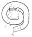
- the suction system 1 according to. Fig. 1 has a spiral Intake pipe 2, which in a front section 3 and a rear section 4 is divided. Surrounds the suction pipe 2 an air chamber 5 with a large air supply opening 6. In a wall opening 7 of the air chamber 5 is a control valve 8 arranged in their guide ring 9. The guide ring 9 is via an annular groove 10 in a suitable annular spring 11 held.
- the control flap serves to determine the effective pipe length of the Adjust intake manifold 2.
- the intake air becomes perpendicular to the Spiral plane through the feed opening 6 into the air chamber 5 sucked in.
- the control flap position 8 When the control flap position 8 is closed, the Air then their way through the intake manifold 2 first through the front section 3 and then through the rear Section 4 on the internal combustion engine no longer shown to take.
- the control flap 8 When the control flap 8 is open, the air takes the direct path between the guide ring and now only flows through the rear section 4 of the Intake pipe 2. Due to the different intake pipe lengths , as stated above, a better torque curve of a fuel engine.
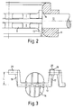
- FIG. 2 shows how the control flap 8 in the guide ring 9 is mounted.
- a journal 12 penetrates the guide ring 9 completely.
- the control flap 8 is on opposite sides with one each Ring projection 13 provided so that an annular shoulder 14th results in the transition to the journal 12. With this The control flap 8 lies on the inner wall 15 of the annular shoulder Guide ring 9 on.
- control valve 8 and the guide ring 9 manufactured in a multi-component injection molding process.
- the different material shrinkage exploited. This is it is possible to play the bearing journal 12 without play to achieve the guide ring 9. Furthermore, it is through this Material selection possible by using the shrinkage Control flap with the ring projection 13 over the ring shoulder 14 without play on the inner wall 15 of the guide ring 9 adapt. This makes storage completely free of play the control valve 8 in the guide ring 9 possible. Out of this this again follows a completely rattle-free operation Arrangement.
- the method mentioned is inexpensive and with consistent quality feasible.
- the reinforcing ribs 16 result in a sufficient Stability of the control flap 8 with little material.
- the actuating levers 17, 18 are so long that the Lever ends at a distance from the axis of the trunnion 12 lie, which corresponds to half the control valve length L. By this long lever formation results in small angular errors in the angular position of the control flaps 8, if in the Couplings 19, 21 an easy game occurs.
- the width of the receiving groove 20 and the plug element 21 can be chosen so that when plugged in Plug element 21 in the receiving groove 20 both components are braced against each other. Because of the existing Elasticity of the plastic is easily possible. Both the operating levers 17, 18 and the associated ones Coupling elements 19, 20, 21 are the same, before described operation with molded. So is also a play-free and rattle-free sequence of several Control flaps 8 each in a guide ring 9 possible.
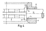
- the representation according to FIG. 4 corresponds to the representation according to Fig. 2, wherein in the current embodiment Metal bushing 22 between guide ring 9 and bearing pin 12 is provided.
- the metal bushing 22 can either in the Guide ring 9 be inserted or the bearing pin 12th encase. However, it can also be compared to both components can be freely rotated.
- the production with metal bushing can also be done in Multi-component injection molding process in an injection mold be made by the metal sleeve around the corresponding core, which is the recess for the bearing journal 12 forms, placed on insertion into the injection mold becomes.
Landscapes
- Engineering & Computer Science (AREA)
- Mechanical Engineering (AREA)
- General Engineering & Computer Science (AREA)
- Chemical & Material Sciences (AREA)
- Combustion & Propulsion (AREA)
- Manufacturing & Machinery (AREA)
- Control Of Throttle Valves Provided In The Intake System Or In The Exhaust System (AREA)
- Characterised By The Charging Evacuation (AREA)
Description
| Führungsring | Steuerklappe | |
| 1. | Polyamid mit 50 % Glasfaserzusatz mit Metallbuchse | Polyamid mit 35 % Glasfaserzusatz mit Metallbuchse |
| 2. | Polyamid mit 50 % Glasfaserzusatz mit Metallbuchse | Polyamid ohne Glasfaserzusatz und ohne Metallbuchse |
| 3. | Polyamid ohne Glasfaserzusatz mit Metallbuchse | Polyamid ohne Glasfaserzusatz jedoch mit Molybdänsulfid mit Metallbuchse |
| 4. | Polyamid ohne Glasfaserzusatz ohne Metallbuchse | Polyamid ohne Glasfaserzusatz jedoch mit Molybdänsulfid und ohne Metallbuchse. |
- Fig. 1
- einen schematischen Querschnitt durch eine Sauganlage;
- Fig. 2
- eine Detailvergrößerung des Lagers der Steuerklappe im Führungsring;
- Fig. 3
- die Draufsicht auf eine Steuerklappe ohne Führungsring; und
- Fig. 4
- ein weiteres Ausführungsbeispiel mit Metallbuchse.
Claims (14)
- Sauganlage für Brennkraftmaschinen mit einem spiralförmigen Saugrohr (2) und einer Einrichtung zur Einstellung der Rohrlänge dieses Saugrohres (2) und mit einer Steuerklappe (8), wobei das spiralförmige Saugrohr (2) eine zentral angeordnete Luftkammer (5) umgibt und wobei die Steuerklappe (8) die Rohrlänge des Saugrohres (2) einstellt, dadurch gekennzeichnet, daß die Steuerklappe (8) in einem Führungsring (9) drehbar gelagert ist, daß der Führungsring (9) und die Steuerklappe (8) eine Einheit bilden, indem der Führungsring (9) einstückig ausgeführt ist und an die Steuerklappe (8) zwei im wesentlichen aneinander gegenüberliegende Lagerzapfen (12) angeformt sind, die den Führungsring (9) durchsetzen, daß das Saugrohr (2) einen sich an die Luftkammer (5) anschließenden vorderen Abschnitt (3) und einen hinteren Abschnitt (4) aufweist, wobei der vordere Abschnitt (3) und der hintere Abschnitt (4) hintereinandergeschaltet die Gesamtrohrlänge des Saugrohres (2) bilden, daß in der Luftkammer (5) ein Wanddurchbruch (7) vorgesehen ist, der in das Saugrohr (2) an der Stelle zwischen dem vorderen Abschnitt (3) und dem hinteren Abschnitt (4) einmündet, und daß in den Wanddurchbruch (7) der Führungsring (9) mit der Steuerklappe (8) eingesetzt ist.
- Sauganlage nach Anspruch 1, dadurch gekennzeichnet, daß an jedem Lagerzapfen (12) eine Ringschulter (13) ausgebildet ist, mittels denen die Steuerklappe (8) in axialer Richtung der Lagerzapfen im Führungsring (9) fixiert ist.
- Sauganlage nach Anspruch 1 oder 2, dadurch gekennzeichnet, daß wenigstens ein Betätigungshebel (17, 18) an einen Lagerzapfen (12) der Steuerklappe (8) angeformt ist.
- Sauganlage nach Anspruch 3, dadurch gekennzeichnet, daß zwei Betätigungshebel (17, 18) vorgesehen sind, die jeweils mit Kupplungselementen (19, 20, 21) versehen sind.
- Sauganlage nach Anspruch 4, dadurch gekennzeichnet, daß die Kupplungselemente (19, 20, 21) als Steckkupplung ausgebildet sind, wobei jeweils zwei Kupplungselemente (19, 20, 21) von zwei benachbart angeordneten Steuerklappen (8) formschlüssig ineinander greifen.
- Sauganlage nach einem der vorhergehenden Ansprüche, dadurch gekennzeichnet, daß der oder die angeformten Betätigungshebel so groß ausgebildet werden, daß das Hebelende um wenigstens die Hälfte (L) der Steuerklappenlänge gegenüber der Drehachse der Steuerklappe (8) beabstandet ist.
- Sauganlage nach einem der vorhergehenden Ansprüche, dadurch gekennzeichnet, daß zur Lagerung der Lagerzapfen (12) im Führungsring (9) wenigstens eine Metallbuchse eingesetzt ist.
- Sauganlage nach einem der vorhergehenden Ansprüche, dadruch gekennzeichnet, daß zur Lagerung der Lagerzapfen (12) wenigstens ein Lagerzapfen (12) mit einer Metallbuchse ummantelt ist.
- Sauganlage nach einem der vorhergehenden Ansprüche, dadurch gekennzeichnet, daß der Führungsring (9) und die Steuerklappe (8) aus Kunststoff gefertigt sind.
- Sauganlage nach Anspruch 9, dadurch gekennzeichnet, daß sowohl der Führungsring (9) als auch die Steuerklappe (8) aus Polyamid gefertigt sind.
- Sauganlage nach Anspruch 9 oder 10, dadurch gekennzeichnet, daß der Kunststoff des Führungsrings (9) und/oder der Steuerklappe (8) durch einen Zusatz verstärkt ist.
- Sauganlage nach Anspruch 11, dadurch gekennzeichnet, daß der Zusatz aus Glasfasern besteht.
- Sauganlage nach einem der vorhergehenden Ansprüche, dadurch gekennzeichnet, daß Verstärkungsrippen (16) zur Erhöhung der Stabilität an die Steuerklappe (8) angeformt sind.
- Sauganlage nach einem der vorhergehenden Ansprüche, dadurch gekennzeichnet, daß der Führungsring (9) sowie das Saugrohr Haltemittel für den Führungsring aufweisen.
Applications Claiming Priority (2)
| Application Number | Priority Date | Filing Date | Title |
|---|---|---|---|
| DE19521169 | 1995-06-10 | ||
| DE19521169A DE19521169A1 (de) | 1995-06-10 | 1995-06-10 | Einrichtung zur Einstellung der Rohrlänge von Saugrohren und Verfahren zu deren Herstellung |
Publications (2)
| Publication Number | Publication Date |
|---|---|
| EP0747587A1 EP0747587A1 (de) | 1996-12-11 |
| EP0747587B1 true EP0747587B1 (de) | 2000-08-16 |
Family
ID=7764073
Family Applications (1)
| Application Number | Title | Priority Date | Filing Date |
|---|---|---|---|
| EP96105400A Expired - Lifetime EP0747587B1 (de) | 1995-06-10 | 1996-04-04 | Einrichtung zur Einstellung der Rohrlänge von Saugrohren und Verfahren zu deren Herstellung |
Country Status (2)
| Country | Link |
|---|---|
| EP (1) | EP0747587B1 (de) |
| DE (2) | DE19521169A1 (de) |
Cited By (1)
| Publication number | Priority date | Publication date | Assignee | Title |
|---|---|---|---|---|
| DE10126063B4 (de) * | 2001-05-28 | 2004-07-15 | Montaplast Gmbh | Klappenvorrichtung |
Families Citing this family (13)
| Publication number | Priority date | Publication date | Assignee | Title |
|---|---|---|---|---|
| DE19702317A1 (de) * | 1997-01-24 | 1998-07-30 | Mann & Hummel Filter | Saugrohr |
| DE19848440A1 (de) * | 1998-10-21 | 2000-04-27 | Mann & Hummel Filter | Klappenmechanismus |
| DE19918777A1 (de) | 1999-04-24 | 2000-10-26 | Mann & Hummel Filter | Schaltklappenverband aus montagegespritzten Schaltklappen oder Klappenmodulen |
| DE19936470A1 (de) | 1999-08-03 | 2001-02-08 | Mann & Hummel Filter | Saugrohranlage |
| JP2001198955A (ja) * | 2000-01-18 | 2001-07-24 | Denso Corp | 通風路切替用ドアの製造方法 |
| FR2804740B1 (fr) * | 2000-02-09 | 2002-08-02 | Mecaplast Sam | Systeme d'obturation pour canalisation de fluide |
| DE10105526B4 (de) * | 2001-02-07 | 2004-12-23 | Robert Bosch Gmbh | Verfahren zur Herstellung einer Klappenanordnung |
| DE10142452A1 (de) * | 2001-08-31 | 2003-03-20 | Siemens Ag | Verfahren zur Herstellung eines Drosselklappenstutzengehäuses und einer Drosselklappe |
| DE10359527A1 (de) * | 2003-12-18 | 2005-07-14 | Daimlerchrysler Ag | Gleitlager für eine Klappe zum Einsetzen in ein Luftansaugsystem |
| WO2005116423A1 (ja) * | 2004-05-31 | 2005-12-08 | Aisan Kogyo Kabushiki Kaisha | スロットルボデーの成形方法及びスロットルボデー |
| EP1764493B1 (de) * | 2005-09-20 | 2013-06-12 | Mahle International GmbH | Frischgasanlage für eine Brennkraftmaschine |
| JP4699984B2 (ja) * | 2006-12-28 | 2011-06-15 | 愛三工業株式会社 | インテークマニホールド |
| DE202007013151U1 (de) * | 2007-09-18 | 2009-02-26 | Mann+Hummel Gmbh | Ansaugsystem für eine Brennkraftmaschine |
Citations (1)
| Publication number | Priority date | Publication date | Assignee | Title |
|---|---|---|---|---|
| US5005532A (en) * | 1989-02-22 | 1991-04-09 | Siemens-Bendix Automotive Electronics Limited | Integrated tuned induction system |
Family Cites Families (10)
| Publication number | Priority date | Publication date | Assignee | Title |
|---|---|---|---|---|
| JPS51151753A (en) * | 1975-06-20 | 1976-12-27 | Matsushita Electric Industrial Co Ltd | Method of producing resin product with slide |
| JPS5948745B2 (ja) * | 1980-10-22 | 1984-11-28 | 日本プラスト株式会社 | ベンチレ−タ−の製造方法 |
| KR900000143B1 (ko) * | 1985-10-04 | 1990-01-20 | 마쯔다 가부시기가이샤 | V형 엔진의 흡기장치 |
| US4660996A (en) * | 1986-01-13 | 1987-04-28 | Dixon Industries Corporation | Bearing and sealing member for moveable shaft |
| FR2606115B1 (fr) * | 1986-10-31 | 1989-03-10 | Peugeot | Vanne a papillon notamment pour vehicule automobile et son application a un carburateur |
| US4860706A (en) * | 1987-09-14 | 1989-08-29 | Aisan Kogyo Kabushiki Kaisha | Throttle body |
| ES2075189T3 (es) * | 1990-10-24 | 1995-10-01 | Volvo Ab | Valvula reguladora. |
| DE4105938A1 (de) * | 1991-02-26 | 1992-08-27 | Vdo Schindling | Stelleinrichtung |
| FR2687601A1 (fr) * | 1992-02-26 | 1993-08-27 | Plastic Omnium Cie | Procede de fabrication d'une vanne papillon, dispositif pour le mettre en óoeuvre et vanne papillon obtenue par ce procede. |
| FR2692622B1 (fr) * | 1992-06-17 | 1994-09-16 | Solex | Organe d'étranglement rotatif pour installation d'alimentation de moteur à combustion interne et corps de papillon en comportant application. |
-
1995
- 1995-06-10 DE DE19521169A patent/DE19521169A1/de not_active Ceased
-
1996
- 1996-04-04 DE DE59605747T patent/DE59605747D1/de not_active Expired - Lifetime
- 1996-04-04 EP EP96105400A patent/EP0747587B1/de not_active Expired - Lifetime
Patent Citations (1)
| Publication number | Priority date | Publication date | Assignee | Title |
|---|---|---|---|---|
| US5005532A (en) * | 1989-02-22 | 1991-04-09 | Siemens-Bendix Automotive Electronics Limited | Integrated tuned induction system |
Cited By (1)
| Publication number | Priority date | Publication date | Assignee | Title |
|---|---|---|---|---|
| DE10126063B4 (de) * | 2001-05-28 | 2004-07-15 | Montaplast Gmbh | Klappenvorrichtung |
Also Published As
| Publication number | Publication date |
|---|---|
| DE59605747D1 (de) | 2000-09-21 |
| EP0747587A1 (de) | 1996-12-11 |
| DE19521169A1 (de) | 1996-12-12 |
Similar Documents
| Publication | Publication Date | Title |
|---|---|---|
| EP0747587B1 (de) | Einrichtung zur Einstellung der Rohrlänge von Saugrohren und Verfahren zu deren Herstellung | |
| DE60029598T2 (de) | Einrichtung zur Durchflusssteuerung in einem Leitungsabschnitt oder einem Durchgang und Ansaugvorrichtung mit einer solchen Einrichtung | |
| DE19918777A1 (de) | Schaltklappenverband aus montagegespritzten Schaltklappen oder Klappenmodulen | |
| DE19504382A1 (de) | Ansaugsystem | |
| DE19614474B4 (de) | Luftansaugkanalsystem für Brennkraftmaschinen | |
| DE60205414T2 (de) | Laserverschweisstes Luftsteuerventil und methode | |
| EP0656991A1 (de) | Saugrohranlage für eine mehrzylinder-brennkraftmaschine. | |
| EP2728156A1 (de) | Regelvorrichtung für eine Verbrennungskraftmaschine | |
| EP0968360B1 (de) | Saugmodul | |
| DE102020108125A1 (de) | Verbindungsanordnung und turbolader, der die verbindungsanordnung umfasst | |
| DE202007013151U1 (de) | Ansaugsystem für eine Brennkraftmaschine | |
| DE69000139T2 (de) | Einlassvorrichtung fuer brennkraftmaschine. | |
| EP1270904B1 (de) | Verfahren zur Herstellung eines Schaltklappenverbandes | |
| EP1388652B1 (de) | Ansaugkanalsystem | |
| WO1996007022A1 (de) | Variable luftansaugvorrichtung | |
| DE102016121721A1 (de) | Verfahren zur Herstellung eines Klappenträgers für eine Abgasklappe | |
| DE102013006196B4 (de) | Saugrohr für Gas einer Brennkraftmaschine mit einer Klappeneinheit | |
| DE10106364B4 (de) | Vergaseranordnung mit einem Choke-Element | |
| DE102004009502B3 (de) | Klappensystem, insbesondere zur Änderung der Strömungsverhältnisse an Einlassventilen | |
| DE19526241B4 (de) | Lufteinlaßkanalsystem für Brennkraftmaschinen | |
| DE102004002641B4 (de) | Modulare Ansaugvorrichtung | |
| DE102011103841A1 (de) | Klappenventilanordnung und Herstellungsverfahren | |
| DE112004000143B4 (de) | Einlasssammler für eine Brennkraftmaschine | |
| DE10352096B4 (de) | Zylinderkopf für eine Hubkolben-Brennkraftmaschine | |
| DE19510723B4 (de) | Saugrohranlage für eine Hubkolben-Brennkraftmaschine |
Legal Events
| Date | Code | Title | Description |
|---|---|---|---|
| PUAI | Public reference made under article 153(3) epc to a published international application that has entered the european phase |
Free format text: ORIGINAL CODE: 0009012 |
|
| AK | Designated contracting states |
Kind code of ref document: A1 Designated state(s): DE FR GB IT |
|
| 17P | Request for examination filed |
Effective date: 19970611 |
|
| 17Q | First examination report despatched |
Effective date: 19970828 |
|
| GRAG | Despatch of communication of intention to grant |
Free format text: ORIGINAL CODE: EPIDOS AGRA |
|
| GRAG | Despatch of communication of intention to grant |
Free format text: ORIGINAL CODE: EPIDOS AGRA |
|
| GRAH | Despatch of communication of intention to grant a patent |
Free format text: ORIGINAL CODE: EPIDOS IGRA |
|
| GRAH | Despatch of communication of intention to grant a patent |
Free format text: ORIGINAL CODE: EPIDOS IGRA |
|
| GRAA | (expected) grant |
Free format text: ORIGINAL CODE: 0009210 |
|
| AK | Designated contracting states |
Kind code of ref document: B1 Designated state(s): DE FR GB IT |
|
| REF | Corresponds to: |
Ref document number: 59605747 Country of ref document: DE Date of ref document: 20000921 |
|
| ITF | It: translation for a ep patent filed | ||
| ET | Fr: translation filed | ||
| GBT | Gb: translation of ep patent filed (gb section 77(6)(a)/1977) |
Effective date: 20001018 |
|
| PLBQ | Unpublished change to opponent data |
Free format text: ORIGINAL CODE: EPIDOS OPPO |
|
| PLBI | Opposition filed |
Free format text: ORIGINAL CODE: 0009260 |
|
| PLBF | Reply of patent proprietor to notice(s) of opposition |
Free format text: ORIGINAL CODE: EPIDOS OBSO |
|
| 26 | Opposition filed |
Opponent name: FILTERWERK MANN+ HUMMEL GMBH Effective date: 20010509 |
|
| PLBF | Reply of patent proprietor to notice(s) of opposition |
Free format text: ORIGINAL CODE: EPIDOS OBSO |
|
| REG | Reference to a national code |
Ref country code: GB Ref legal event code: IF02 |
|
| PLBF | Reply of patent proprietor to notice(s) of opposition |
Free format text: ORIGINAL CODE: EPIDOS OBSO |
|
| PLBF | Reply of patent proprietor to notice(s) of opposition |
Free format text: ORIGINAL CODE: EPIDOS OBSO |
|
| RDAH | Patent revoked |
Free format text: ORIGINAL CODE: EPIDOS REVO |
|
| APAC | Appeal dossier modified |
Free format text: ORIGINAL CODE: EPIDOS NOAPO |
|
| APAC | Appeal dossier modified |
Free format text: ORIGINAL CODE: EPIDOS NOAPO |
|
| APBU | Appeal procedure closed |
Free format text: ORIGINAL CODE: EPIDOSNNOA9O |
|
| PLCK | Communication despatched that opposition was rejected |
Free format text: ORIGINAL CODE: EPIDOSNREJ1 |
|
| PLBN | Opposition rejected |
Free format text: ORIGINAL CODE: 0009273 |
|
| STAA | Information on the status of an ep patent application or granted ep patent |
Free format text: STATUS: OPPOSITION REJECTED |
|
| 27O | Opposition rejected |
Effective date: 20031119 |
|
| APAA | Appeal reference recorded |
Free format text: ORIGINAL CODE: EPIDOS REFN |
|
| APAH | Appeal reference modified |
Free format text: ORIGINAL CODE: EPIDOSCREFNO |
|
| PLAB | Opposition data, opponent's data or that of the opponent's representative modified |
Free format text: ORIGINAL CODE: 0009299OPPO |
|
| PGFP | Annual fee paid to national office [announced via postgrant information from national office to epo] |
Ref country code: FR Payment date: 20110427 Year of fee payment: 16 |
|
| PGFP | Annual fee paid to national office [announced via postgrant information from national office to epo] |
Ref country code: GB Payment date: 20110419 Year of fee payment: 16 |
|
| PGFP | Annual fee paid to national office [announced via postgrant information from national office to epo] |
Ref country code: IT Payment date: 20110427 Year of fee payment: 16 |
|
| PGFP | Annual fee paid to national office [announced via postgrant information from national office to epo] |
Ref country code: DE Payment date: 20110628 Year of fee payment: 16 |
|
| GBPC | Gb: european patent ceased through non-payment of renewal fee |
Effective date: 20120404 |
|
| REG | Reference to a national code |
Ref country code: FR Ref legal event code: ST Effective date: 20121228 |
|
| PG25 | Lapsed in a contracting state [announced via postgrant information from national office to epo] |
Ref country code: GB Free format text: LAPSE BECAUSE OF NON-PAYMENT OF DUE FEES Effective date: 20120404 |
|
| REG | Reference to a national code |
Ref country code: DE Ref legal event code: R119 Ref document number: 59605747 Country of ref document: DE Effective date: 20121101 |
|
| PG25 | Lapsed in a contracting state [announced via postgrant information from national office to epo] |
Ref country code: IT Free format text: LAPSE BECAUSE OF NON-PAYMENT OF DUE FEES Effective date: 20120404 Ref country code: FR Free format text: LAPSE BECAUSE OF NON-PAYMENT OF DUE FEES Effective date: 20120430 |
|
| PG25 | Lapsed in a contracting state [announced via postgrant information from national office to epo] |
Ref country code: DE Free format text: LAPSE BECAUSE OF NON-PAYMENT OF DUE FEES Effective date: 20121101 |