EP0968360B1 - Saugmodul - Google Patents
Saugmodul Download PDFInfo
- Publication number
- EP0968360B1 EP0968360B1 EP98908101A EP98908101A EP0968360B1 EP 0968360 B1 EP0968360 B1 EP 0968360B1 EP 98908101 A EP98908101 A EP 98908101A EP 98908101 A EP98908101 A EP 98908101A EP 0968360 B1 EP0968360 B1 EP 0968360B1
- Authority
- EP
- European Patent Office
- Prior art keywords
- coupling means
- intake module
- module according
- flaps
- main rod
- Prior art date
- Legal status (The legal status is an assumption and is not a legal conclusion. Google has not performed a legal analysis and makes no representation as to the accuracy of the status listed.)
- Expired - Lifetime
Links
- 230000008878 coupling Effects 0.000 claims description 52
- 238000010168 coupling process Methods 0.000 claims description 52
- 238000005859 coupling reaction Methods 0.000 claims description 52
- 239000000463 material Substances 0.000 claims description 13
- 239000004033 plastic Substances 0.000 claims description 10
- 229920003023 plastic Polymers 0.000 claims description 10
- 238000002485 combustion reaction Methods 0.000 claims description 8
- 239000007789 gas Substances 0.000 claims description 8
- 238000001746 injection moulding Methods 0.000 claims description 2
- 229920001169 thermoplastic Polymers 0.000 claims description 2
- 230000006698 induction Effects 0.000 claims 4
- 238000005273 aeration Methods 0.000 claims 1
- 230000029058 respiratory gaseous exchange Effects 0.000 claims 1
- 230000007704 transition Effects 0.000 claims 1
- 238000004519 manufacturing process Methods 0.000 description 5
- 239000007822 coupling agent Substances 0.000 description 4
- 238000003860 storage Methods 0.000 description 3
- 238000005452 bending Methods 0.000 description 2
- 238000009826 distribution Methods 0.000 description 2
- 238000002347 injection Methods 0.000 description 2
- 239000007924 injection Substances 0.000 description 2
- 229920006324 polyoxymethylene Polymers 0.000 description 2
- 239000000243 solution Substances 0.000 description 2
- 238000009423 ventilation Methods 0.000 description 2
- -1 PolyoxyMethylen Polymers 0.000 description 1
- 239000011324 bead Substances 0.000 description 1
- 230000005540 biological transmission Effects 0.000 description 1
- 238000005266 casting Methods 0.000 description 1
- 238000006243 chemical reaction Methods 0.000 description 1
- 238000010276 construction Methods 0.000 description 1
- 238000005520 cutting process Methods 0.000 description 1
- 230000000694 effects Effects 0.000 description 1
- 239000013013 elastic material Substances 0.000 description 1
- 210000003746 feather Anatomy 0.000 description 1
- 239000000446 fuel Substances 0.000 description 1
- 238000010438 heat treatment Methods 0.000 description 1
- 239000002184 metal Substances 0.000 description 1
- 230000001681 protective effect Effects 0.000 description 1
- 230000003014 reinforcing effect Effects 0.000 description 1
- 238000007789 sealing Methods 0.000 description 1
- 239000000725 suspension Substances 0.000 description 1
- 239000004416 thermosoftening plastic Substances 0.000 description 1
- 230000003313 weakening effect Effects 0.000 description 1
Images
Classifications
-
- F—MECHANICAL ENGINEERING; LIGHTING; HEATING; WEAPONS; BLASTING
- F02—COMBUSTION ENGINES; HOT-GAS OR COMBUSTION-PRODUCT ENGINE PLANTS
- F02M—SUPPLYING COMBUSTION ENGINES IN GENERAL WITH COMBUSTIBLE MIXTURES OR CONSTITUENTS THEREOF
- F02M13/00—Arrangements of two or more separate carburettors; Carburettors using more than one fuel
- F02M13/02—Separate carburettors
- F02M13/023—Special construction of the control rods
-
- F—MECHANICAL ENGINEERING; LIGHTING; HEATING; WEAPONS; BLASTING
- F02—COMBUSTION ENGINES; HOT-GAS OR COMBUSTION-PRODUCT ENGINE PLANTS
- F02B—INTERNAL-COMBUSTION PISTON ENGINES; COMBUSTION ENGINES IN GENERAL
- F02B27/00—Use of kinetic or wave energy of charge in induction systems, or of combustion residues in exhaust systems, for improving quantity of charge or for increasing removal of combustion residues
- F02B27/02—Use of kinetic or wave energy of charge in induction systems, or of combustion residues in exhaust systems, for improving quantity of charge or for increasing removal of combustion residues the systems having variable, i.e. adjustable, cross-sectional areas, chambers of variable volume, or like variable means
- F02B27/0205—Use of kinetic or wave energy of charge in induction systems, or of combustion residues in exhaust systems, for improving quantity of charge or for increasing removal of combustion residues the systems having variable, i.e. adjustable, cross-sectional areas, chambers of variable volume, or like variable means characterised by the charging effect
- F02B27/0215—Oscillating pipe charging, i.e. variable intake pipe length charging
-
- F—MECHANICAL ENGINEERING; LIGHTING; HEATING; WEAPONS; BLASTING
- F02—COMBUSTION ENGINES; HOT-GAS OR COMBUSTION-PRODUCT ENGINE PLANTS
- F02B—INTERNAL-COMBUSTION PISTON ENGINES; COMBUSTION ENGINES IN GENERAL
- F02B27/00—Use of kinetic or wave energy of charge in induction systems, or of combustion residues in exhaust systems, for improving quantity of charge or for increasing removal of combustion residues
- F02B27/02—Use of kinetic or wave energy of charge in induction systems, or of combustion residues in exhaust systems, for improving quantity of charge or for increasing removal of combustion residues the systems having variable, i.e. adjustable, cross-sectional areas, chambers of variable volume, or like variable means
- F02B27/0226—Use of kinetic or wave energy of charge in induction systems, or of combustion residues in exhaust systems, for improving quantity of charge or for increasing removal of combustion residues the systems having variable, i.e. adjustable, cross-sectional areas, chambers of variable volume, or like variable means characterised by the means generating the charging effect
- F02B27/0268—Valves
- F02B27/0273—Flap valves
-
- F—MECHANICAL ENGINEERING; LIGHTING; HEATING; WEAPONS; BLASTING
- F02—COMBUSTION ENGINES; HOT-GAS OR COMBUSTION-PRODUCT ENGINE PLANTS
- F02D—CONTROLLING COMBUSTION ENGINES
- F02D9/00—Controlling engines by throttling air or fuel-and-air induction conduits or exhaust conduits
- F02D9/08—Throttle valves specially adapted therefor; Arrangements of such valves in conduits
- F02D9/10—Throttle valves specially adapted therefor; Arrangements of such valves in conduits having pivotally-mounted flaps
-
- F—MECHANICAL ENGINEERING; LIGHTING; HEATING; WEAPONS; BLASTING
- F02—COMBUSTION ENGINES; HOT-GAS OR COMBUSTION-PRODUCT ENGINE PLANTS
- F02D—CONTROLLING COMBUSTION ENGINES
- F02D9/00—Controlling engines by throttling air or fuel-and-air induction conduits or exhaust conduits
- F02D9/08—Throttle valves specially adapted therefor; Arrangements of such valves in conduits
- F02D9/10—Throttle valves specially adapted therefor; Arrangements of such valves in conduits having pivotally-mounted flaps
- F02D9/1035—Details of the valve housing
- F02D9/104—Shaping of the flow path in the vicinity of the flap, e.g. having inserts in the housing
-
- F—MECHANICAL ENGINEERING; LIGHTING; HEATING; WEAPONS; BLASTING
- F02—COMBUSTION ENGINES; HOT-GAS OR COMBUSTION-PRODUCT ENGINE PLANTS
- F02D—CONTROLLING COMBUSTION ENGINES
- F02D9/00—Controlling engines by throttling air or fuel-and-air induction conduits or exhaust conduits
- F02D9/08—Throttle valves specially adapted therefor; Arrangements of such valves in conduits
- F02D9/10—Throttle valves specially adapted therefor; Arrangements of such valves in conduits having pivotally-mounted flaps
- F02D9/1065—Mechanical control linkage between an actuator and the flap, e.g. including levers, gears, springs, clutches, limit stops of the like
-
- F—MECHANICAL ENGINEERING; LIGHTING; HEATING; WEAPONS; BLASTING
- F02—COMBUSTION ENGINES; HOT-GAS OR COMBUSTION-PRODUCT ENGINE PLANTS
- F02D—CONTROLLING COMBUSTION ENGINES
- F02D9/00—Controlling engines by throttling air or fuel-and-air induction conduits or exhaust conduits
- F02D9/08—Throttle valves specially adapted therefor; Arrangements of such valves in conduits
- F02D9/10—Throttle valves specially adapted therefor; Arrangements of such valves in conduits having pivotally-mounted flaps
- F02D9/109—Throttle valves specially adapted therefor; Arrangements of such valves in conduits having pivotally-mounted flaps having two or more flaps
-
- F—MECHANICAL ENGINEERING; LIGHTING; HEATING; WEAPONS; BLASTING
- F02—COMBUSTION ENGINES; HOT-GAS OR COMBUSTION-PRODUCT ENGINE PLANTS
- F02D—CONTROLLING COMBUSTION ENGINES
- F02D9/00—Controlling engines by throttling air or fuel-and-air induction conduits or exhaust conduits
- F02D9/08—Throttle valves specially adapted therefor; Arrangements of such valves in conduits
- F02D9/10—Throttle valves specially adapted therefor; Arrangements of such valves in conduits having pivotally-mounted flaps
- F02D9/109—Throttle valves specially adapted therefor; Arrangements of such valves in conduits having pivotally-mounted flaps having two or more flaps
- F02D9/1095—Rotating on a common axis, e.g. having a common shaft
-
- Y—GENERAL TAGGING OF NEW TECHNOLOGICAL DEVELOPMENTS; GENERAL TAGGING OF CROSS-SECTIONAL TECHNOLOGIES SPANNING OVER SEVERAL SECTIONS OF THE IPC; TECHNICAL SUBJECTS COVERED BY FORMER USPC CROSS-REFERENCE ART COLLECTIONS [XRACs] AND DIGESTS
- Y02—TECHNOLOGIES OR APPLICATIONS FOR MITIGATION OR ADAPTATION AGAINST CLIMATE CHANGE
- Y02T—CLIMATE CHANGE MITIGATION TECHNOLOGIES RELATED TO TRANSPORTATION
- Y02T10/00—Road transport of goods or passengers
- Y02T10/10—Internal combustion engine [ICE] based vehicles
- Y02T10/12—Improving ICE efficiencies
Definitions
- the invention relates to a suction module, in particular for a Internal combustion engine, with an intake tract with at least 2 Intake channels and one closing means in each case in an intake channel to influence the flow cross-section.
- Such a suction module is e.g. B. from US 4,823,748.
- This document discloses a suction device for an internal combustion engine with at least 2 intake channels, wherein each have a closing means in one of the intake ducts Influencing a flow cross section is provided.
- These locking means are operated by a common actuating means controlled via coupling means.
- a tolerance compensation between actuating means and closing means is about reaches an elastic range, the elasticity is generated by separate elastic components.
- the object of the invention is a suction module with locking means to create in intake ducts of an intake tract that avoids the disadvantages of the prior art in which Manufacturing requires little effort and is reliable Ensures function.
- the elastic region lies in the region of a material weakening, preferably a material thinning, perforation or recess.
- the strength is thus reduced at this point and, as it were, a joint or a bending region or elastic region is created.
- a change in material is also possible, for example local heating or irradiation with UV light, which can lead to a change or softening of the area in question.
- the coupling means in several parts, however, they are preferably in one piece, so that manufacturing and assembly effort can be reduced. With a multi-part Execution of the coupling means are advantageously identical Components can be used or assembled.
- the coupling means at least one main rod, in particular at least has an elastic range.
- A can thus be advantageous Main bar at least two locking means directly or indirectly connect with each other, and especially when power transmission roughly slender in its longitudinal axis and yet sufficient be dimensioned stable.
- the coupling agent to the Locking means must be stored, since their storage in the Intake channels required for reliable function anyway is. Through this type of storage of the coupling agent becomes a possible tolerance compensation through elasticity improved between actuating means and closing means.
- the coupling means can have connecting elements, by means of which they are particularly articulated with the locking means are connectable, the connecting elements preferably project approximately perpendicularly from the coupling means.
- the coupling means therefore do not need to be directly attached to the Locking means to run.
- the connecting elements be designed as branch bars.
- connection elements elastic or articulated with a main rod and / or other components of the coupling agent are connected, wherein they are preferably dimensionally stable are provided and the elastic region in the connection is.
- a connection can, for example, in one Connection area with a thin or an elasticity forming cross section.
- Flaps are preferably used as the closing means, especially essentially round flaps around a Axis are rotatable. Such flaps are easy to manufacture and installable and block due to their relatively low Cross section in the OPEN position only a small part the flow cross section of an intake duct. Preferably they are from the coupling means via link levers and ball joints or the connecting elements articulated.
- all the closing means essentially take that same position, two positions in particular being provided are, preferably by means of tolerance compensation reachable a CLOSED and OPEN position, each are determined by stops for the locking means. Consequently can individual locking means pressed against an end position and be further loaded by means of the coupling means further, not yet completely in the same position, also to press against their stops. Then can from the actuating means to the closing means or Flaps exerted force can be reduced or switched off.
- Rotary actuators and are possible an essentially translatory movement of the coupling means, preferably via an eccentric to the Actuating means and an exceptional opening on the coupling means a conversion of the rotary into a longitudinal movement takes place, in particular essentially in the direction of the longitudinal axis the coupling means, the actuating means of an actuator and gear can be formed.
- the coupling means it prefers several main rods with outgoing ones Legs as connecting elements for locking devices in the form of flaps.
- the main bars can be one below the other be articulated, for example the elastic region as material thinning in connection with the Be legs and preferably the actuation of two main rods, with which two flaps are connected are connected by one to the two main rods third main bar.
- the main bars are advantageous designed to be essentially identical to manufacturing and reduce assembly effort.
- the coupling means in one piece a main rod and branch rods projecting vertically therefrom for connection with the locking means in an intake duct to execute.
- the elastic range can be as Cross-sectional change or taper of the branch bars in the Comparison to the main bar over the entire length of the branch bars extend, with their vertical arrangement Elasticity can be achieved.
- the cross-sectional taper can also only in a limited range, preferably that Connection area, be designed as a joint. The movement takes place essentially in the direction of the main rod.
- the coupling means and / or the connecting elements are preferably by injection molding, for example from Plastic, manufactured.
- a thermoplastic is particularly preferred Plastic used, depending on the rigidity or elasticity with different and different oriented cross sections or profiles.
- annular gap For supplying gases from the crankcase ventilation of the Exhaust gas recirculation or tank ventilation to an intake duct an annular gap can be assigned to each intake duct. This represents a simple type of gas supply.
- the suction module is preferably made of a plastic injection molded part or several interconnected injection molded parts manufactured. This means considerable weight advantages compared to metallic suction modules, furthermore it can simply recycle it.
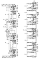
- Fig. 1 shows an inventive suction module 11 in Longitudinal section, with only the switchable intake ducts 12 are shown.
- these intake ducts 12 are in Flaps 13 shown side view, which on a in flap plane through the center axis 14 rotatable are stored. In the position shown in FIG. 1, which is the same for all flaps 13, they close the Intake ducts 12 completely.
- Either the articulation lever 16 can be elastic, or else preferably axis 14 for limited torsion with a certain elasticity, for example by Use a suitable material or through a cross-sectional taper as an elastic area.
- main rods 17 one of which is the two on the left and another is the two right flaps connects together.
- Main rod 17 is the two outer main rods connected, the movement through this central main rod is initiated.
- All three main rods 17 are essentially identical executed, with a straight main part 18, of the two Ends two short legs 19 as connecting elements protrude vertically.
- the junction between the Legs 19 and the main part 18 can be clearly seen with reduced cross section as an elastic area through a Material thinning 20 executed.
- one elastic mobility of the legs 19 relative to the main part 18 reached within certain limits, which in this case approximately as a pivoting of the legs by the material thinning 20 as a joint.
- Are at their outer ends the legs 19 connected to the link levers 16, as in Fig. 4 is shown in detail. Since in the in Fig. 1st arrangement shown essentially only forces in the Drawing level and here again mainly in the direction of the Main parts 18 occur, only one plays in this level or effective elasticity of an elastic in this direction Area of the main rods 17 as a coupling means.
- the coupling means are not driven by a shown actuator with gear, on the one with a square Cross-section of driven shaft 22 a linkage 23 is placed, that in comparison to the output axis eccentrically with the main part 18 of the middle skin rod 17 connected is.
- the swivel curve is shown in dash-dot lines in FIG. 1 of the articulated part 23, as well as in each of the Flaps 13. It can be seen that a pivoting by about 90 ° counterclockwise is possible.
- the movement of the Main rods 17 consists of rotary and translational components together, with the geometrically identical conditions of the articulation part 23 and the linkage lever 16 perform an identical movement. It can be seen that with a rotation of 90 ° against the Clockwise the flaps 13 in Fig. 1 are vertical and thus run approximately in the direction of the intake duct 12, and release a maximum free flow area. Between the wall of the intake duct 12 and that of the suction module 11 an annular gap 24 is clearly recognizable through the crankcase gases or fuel vapors can be supplied to the engine.
- the main part 18 of the main rod 17 is a force made rigid in its longitudinal direction.
- the legs 19 with the link levers 16 are the main rods 17 interconnected by ball joints, see FIG. 4.
- the middle main rod 17 differs from that outer two only in that they are roughly in the middle is rotatably connected to the link 23.
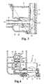
- Fig. 2 the suction module 11 is shown in section, the Cutting plane runs through the middle of the flaps 13. Also here you can see the flaps in the CLOSED position.
- Fig. 3 shows a detailed view of the suction module 11, the connected to a carrier part 39 via a welded connection is.
- a socket 41 is located in the suction module 11, preferably Made of metal, over which the suction module is attached to the cylinder head can attach an internal combustion engine.
- Crankcase gases which have to be returned to the combustion chamber via the opening 42, are via the opening 43 in the Cavity of the socket 41 passed and flow from there over the Opening 44 in a distribution channel 45. From distribution channel 45 they arrive at the respective one, as shown in FIG. 2 Annular gap 24.
- FIG. 4 shows the suction module from FIG. 1 in cross section, the flap 13, in contrast to FIG. 1, in the OPEN position is located and the intake duct 12 as large as possible Flow cross-section has.
- the round shape is clear to recognize the flap acting as a closing means.
- the Axis 14 is at both ends in plastic bearing bushings 26 stored, preferably made of self-lubricating plastic can exist, for example POM (PolyoxyMethylen).
- POM PolyoxyMethylen
- the link lever 16 is attached on the left in FIG. 4 via the plastic bearing bush 26 protruding end provided with a square cross section is, the link lever 16 is attached. He has one protruding ball pin 27, in a ball joint bushing 28 of the leg 19 engages. How to at the Recognizes profile supervision of the main rod 17, this one Taper from the main part 18 to the leg 19. Consequently can also be an elastic or soft design of the Main rod 17 take place.
- the intake duct 12 surrounding a seal 31 as a tolerance-compensating element between a flap bracket 33, which the plastic bearing bushes 26 contains, and the base structure or the housing 32nd of the suction module 11 is provided. That way one is in that Housing 32 insertable locking device carrier possible, the can be closed particularly well by a round flap 13 or is steplessly openable. This has the advantage that in Contrary to the rest of the housing 32 of the suction module 11 as also the intake duct 12 only the flap carrier 33 with small Component tolerances to be manufactured is reliable To achieve sealing by the flap 13.
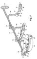
- the coupling means is in one piece in FIG. 5 Execution shown in oblique view, but without is further interchangeable with the other version.
- she consists of an elongated main rod 17, of which three branches to the left rear and right front 35 go vertically. Both the main rod 17 and the Branch rods 35 each have a constant cross section on, which can be seen, for example, as on the main rod Cross ribbing can be carried out.
- the elasticity in the branch bars is determined solely by the Choice of a suitable cross-section achieved over the total length from the connection to the main bar to the Ball joint bushings remains the same, with the backwards projecting branch rods have a different cross section than the protruding ones.
- Cross section and length of the Branch rods 35 are designed so that all ball joint bushings 28 at the ends of the branch rods each the same elasticity with respect to the main rod 17 is given. This means in relation to Fig. 5 that the rear outgoing branch rods 35 due to their significantly lower Length is shorter and therefore higher elasticity conditional cross-section than the outgoing forward Branch bars.
- flap 13 can and axis 14 in one piece or consist of a casting, possibly even with molded link 16.
- reinforcing ribs 36 are provided.
- Flap support 33 made of a plastic material described above exist and approximately as a tubular section can be formed.
- On its right part is one of the Plastic bearing bushes 26 can be seen in the right end the axis 14 is mounted. It has an approximately bead shape on its inner wall protruding stop 38 on the forming a half arc between the bearing bushes 26 extends.
- the flap 13 strikes from below him, so that in this case an actuation of the coupling means clockwise or to the right behind.
- the the other half arc forming stop is located then below the flap so that it is against him from above is present.
- the flap seals against in the respective position these stops the intake duct.
- the flap bracket 33 is inserted into the housing 32 of the suction module 11 and preferably sealed against this by a seal 31.
- the main rod 17 has at its right end a receiving opening 37 running approximately perpendicular to it in which a pivot pin 30 or an eccentric pin Actuator engages for actuation.
- the movement of the Main rod 17 and the link lever 16 and the flaps 13 is similar to that described in Fig. 1.
- the housing 32 of the suction module 11 the flap holder 33 receiving the flap carrier 33 in the Intake channels 12 used.
- the main rods 17 by means of the ball joint connections plugged in, both in the embodiments according to FIG. 1 5 is largely the same.
- the coupling means are connected to the actuator, for example via a pivot pin 30, which in a Receiving opening 37 on the coupling means or a main rod 17 engages.
- the rotary actuation of the actuator is essentially one of rotational and translational Components existing movement of the main rod / s 17 implemented, the at the ends of the legs 19 or Branch rods 35 located ball joint bushings 28 a the arc corresponding to the movement of the pivot pin 30 follow up.
- This circular section preferably extends over 90 °, the two maximum end positions one CLOSED position and one OPEN position are. Stops can be present in the flap supports 33 be a movement of the flaps does not have any of the effect both end positions.
- the invention is particularly advantageous with such stops can be combined, as for example something in the position leading flaps 13 already through the stops reach predetermined end position while by continuing Movement of the coupling means all further rotatable flaps also against the stops in their End positions can run.
- Elasticity between closing means or flaps 13 and Actuating means or actuator is the further movement the coupling means with one already at the stop Flap allows, the elasticity is equal to that Tolerance between the positions or the stops of the End positions of the flaps.
- the flaps therefore need 13 not being in exactly the same position at all times, since this is due to the tolerance compensation due to the elasticity in the two important positions, the CLOSED and the OPEN position is achieved automatically.
Landscapes
- Engineering & Computer Science (AREA)
- Chemical & Material Sciences (AREA)
- Combustion & Propulsion (AREA)
- Mechanical Engineering (AREA)
- General Engineering & Computer Science (AREA)
- Characterised By The Charging Evacuation (AREA)
Description
- Fig. 1
- einen Längsschnitt durch ein erfindungsgemäßes Saugmodul mit mehrteiligen Kupplungsmitteln,
- Fig. 2
- die Anordnung der Klappen in dem jeweiligen Kanal eines Saugmoduls,
- Fig. 3
- eine Detaildarstellung des Saugmoduls,
- Fig. 4
- einen Querschnitt durch das Saugmodul aus Fig. 1 zur Verdeutlichung der Lagerung einer Schließklappe samt Kupplungsmitteln und Klappenantrieb und
- Fig. 5
- Schrägansicht von einteilig ausgeführten Kupplungsmitteln samt daran befestigten Klappen.
Claims (16)
- Saugmodul, insbesondere für Brennkraftmaschinen, mit einem Ansaugtrakt mit wenigstens zwei Ansaugkanälen (12) und jeweils einem Schließmittel (13, 14) in einem Ansaugkanal zur Beeinflussung eines Durchflußquerschnittes, wobei wenigstens zwei Schließmittel von gemeinsamen Betätigungsmitteln über Kupplungsmittel (17, 18, 35) betätigbar sind, und wobei die Kupplungsmittel für einen Toleranzausgleich zwischen Betätigungsmitteln und Schließmitteln wenigstens einen elastischen Bereich aufweisen, dadurch gekennzeichnet, daß der elastische Bereich im Bereich einer Materialschwächung, vorzugsweise einer Materialverdünnung (20), Perforierung oder Ausnehmung liegt.
- Saugmodul nach Anspruch 1, gekennzeichnet durch wenigstens ein elastisches Gelenk zwischen Betätigungsmitteln, Kupplungsmitteln und / oder Schließmitteln.
- Saugmodul nach einem der vorhergehenden Ansprüche, dadurch gekennzeichnet, daß die Kupplungsmittel mehrteilig sind.
- Saugmodul nach einem der Ansprüche 1 bis 2, dadurch gekennzeichnet, daß die Kupplungsmittel einteilig sind.
- Saugmodul nach einem der vorhergehenden Ansprüche, dadurch gekennzeichnet, daß die Kupplungsmittel wenigstens eine Hauptstange (17) aufweisen, insbesondere mit wenigstens einem elastischen Bereich, und vorzugsweise im wesentlichen an den Schließmitteln gelagert sind.
- Saugmodul nach einem der vorhergehenden Ansprüche, dadurch gekennzeichnet, daß die Kupplungsmittel Verbindungselemente, insbesondere Zweigstangen (35), aufweisen, mittels derer sie insbesondere gelenkig mit den Schließmitteln verbunden sind, wobei die Verbindungselemente von den Kupplungsmitteln vorzugsweise etwa senkrecht abstehen.
- Saugmodul nach Anspruch 6, dadurch gekennzeichnet, daß der elastische Bereich die Verbindungselemente umfaßt, die insbesondere formsteif mit den vorzugsweise einteilig ausgeführten Kupplungsmitteln verbunden sind, wobei er sich insbesondere über deren gesamte Länge erstreckt.
- Saugmodul nach Anspruch 6, dadurch gekennzeichnet, daß die Verbindungselemente elastisch oder gelenkig mit einer Hauptstange (17) und/oder weiteren Komponenten der Kupplungsmittel verbunden sind, wobei sie vorzugsweise formsteif ausgeführt sind und der elastische Bereich in der Verbindung liegt.
- Saugmodul nach einem der vorhergehenden Ansprüche, dadurch gekennzeichnet, daß die Schließmittel Klappen, insbesondere im wesentlichen runde Klappen (13), sind, die um eine Achse (14) drehbar sind, wobei sie vorzugsweise über Anlenkhebel (16) und Kugelgelenke (27,28) von den Kupplungsmitteln bzw. den Verbindungselementen anlenkbar sind.
- Saugmodul nach einem der vorhergehenden Ansprüche, dadurch gekennzeichnet, daß alle Schließmittel im wesentlichen die gleiche Stellung einnehmen, wobei insbesondere zwei Stellungen vorgesehen sind, vorzugsweise mittels des Toleranzausgleiches erreichbar eine GESCHLOSSEN- und eine OFFEN-Stellung, die jeweils durch Anschläge bestimmt sind.
- Saugmodul nach einem der vorhergehenden Ansprüche, gekennzeichnet durch rotatorisch arbeitende Betätigungsmittel und eine im wesentlichen translatorische Bewegung der Kupplungsmittel, wobei vorzugsweise über einen Exzenterzapfen oder Anlenkzapfen (30) an den Betätigungsmitteln und eine Aufnahmeöffnung (37) an den Kupplungsmitteln eine Umsetzung in eine Längsbewegung erfolgt, insbesondere im wesentlichen in Richtung der Längsachse der Kupplungsmittel.
- Saugmodul nach einem der Ansprüche 3 oder 7 bis 11, dadurch gekennzeichnet, daß die Kupplungsmittel aus mehreren Hauptstangen (17) bestehen mit davon abgehenden Zweigstangen (35) als Verbindungselemente für Schließmittel in Form von Klappen (13), wobei die Hauptstangen untereinander gelenkig verbunden sind und der elastische Bereich als Materialverdünnung (20) in der Verbindung mit den Schenkeln liegt, und wobei die Betätigung von zwei Hauptstangen, mit denen jeweils zwei Klappen verbunden sind, durch eine mit den zwei Hauptstangen verbundene dritte Hauptstange erfolgt, wobei vorzugsweise die Hauptstangen identisch sind.
- Saugmodul nach einem der Ansprüche 4 bis 11, dadurch gekennzeichnet, daß die Kupplungsmittel einteilig mit einer Hauptstange (17) und davon senkrecht abstehenden Zweigstangen (35) zur Verbindung mit den Schließmitteln in Form von Klappen (13) ausgeführt sind, wobei sich der elastische Bereich als Querschnittsverjüngung der Zweigstangen im Vergleich zur Hauptstange und deren senkrechte Anordnung daran ausgebildet ist, und wobei die Betätigung über einen Stellmotor mit einem antriebsseitigen Exzenterzapfen (30) und eine senkrecht zu der Hauptstange verlaufende, angeformte Aufnahmeöffnung (37) im wesentlichen in Richtung der Hauptstange erfolgt.
- Saugmodul nach einem der vorhergehenden Ansprüche, dadurch gekennzeichnet, daß die Kupplungsmittel und/oder Verbindungselemente vorzugsweise im Spritzgußverfahren aus Kunststoff gefertigt sind, insbesondere aus einem thermoplastischen Kunststoff.
- Saugmodul nach einem der vorhergehenden Ansprüche, dadurch gekennzeichnet, daß jedem Ansaugkanal (12) ein Ringspalt (24) zugeordnet ist, welchem Gase aus der Kurbelgehäuselüftung der Abgasrückführung oder der Tankentlüftung zuführbar sind.
- Saugmodul nach einem der vorhergehenden Ansprüche, dadurch gekennzeichnet, daß an der der Brennkraftmaschine zugewandten Stirnseite des Saugmoduls (11) eine Dichtung (31) als toleranzausgleichendes Element vorgesehen ist, vorzugsweise zwischen einem Klappenträger (33) als Einsatz in einem Ansaugkanal (12) und dem Gehäuse des Saugmoduls (32).
Applications Claiming Priority (3)
| Application Number | Priority Date | Filing Date | Title |
|---|---|---|---|
| DE19711538 | 1997-03-20 | ||
| DE19711538 | 1997-03-20 | ||
| PCT/EP1998/000958 WO1998042969A1 (de) | 1997-03-20 | 1998-02-19 | Saugmodul |
Publications (2)
| Publication Number | Publication Date |
|---|---|
| EP0968360A1 EP0968360A1 (de) | 2000-01-05 |
| EP0968360B1 true EP0968360B1 (de) | 2001-07-18 |
Family
ID=7823955
Family Applications (1)
| Application Number | Title | Priority Date | Filing Date |
|---|---|---|---|
| EP98908101A Expired - Lifetime EP0968360B1 (de) | 1997-03-20 | 1998-02-19 | Saugmodul |
Country Status (5)
| Country | Link |
|---|---|
| US (1) | US6321718B1 (de) |
| EP (1) | EP0968360B1 (de) |
| DE (2) | DE19800207A1 (de) |
| WO (1) | WO1998042969A1 (de) |
| ZA (1) | ZA982070B (de) |
Cited By (1)
| Publication number | Priority date | Publication date | Assignee | Title |
|---|---|---|---|---|
| FR2891886A1 (fr) | 2005-10-07 | 2007-04-13 | Mark Iv Systemes Moteurs Soc P | Dispositif de regulation a clapet et collecteur d'admission comprenant au moins un tel dispositif |
Families Citing this family (15)
| Publication number | Priority date | Publication date | Assignee | Title |
|---|---|---|---|---|
| FR2793539B1 (fr) * | 1999-05-10 | 2001-07-27 | Mark Iv Systemes Moteurs Sa | Dispositif a clapet, collecteur d'admission comportant au moins un tel dispositif et son procede de fabrication |
| DE19936456A1 (de) * | 1999-08-03 | 2001-02-08 | Mann & Hummel Filter | Ventil |
| DE19951412A1 (de) * | 1999-10-26 | 2001-05-03 | Mann & Hummel Filter | Schalteinheit |
| DE10032740A1 (de) * | 2000-07-05 | 2002-02-21 | Mann & Hummel Filter | Luftansaugvorrichtung für eine Brennkraftmaschine |
| US6604506B2 (en) | 2000-09-28 | 2003-08-12 | Mazda Motor Corporation | Intake manifold of engine |
| FR2819557B1 (fr) * | 2001-01-17 | 2003-09-19 | Mark Iv Systemes Moteurs Sa | Collecteur ou repartiteur d'admission pour moteur thermique et procede de fabrication |
| DE10112070A1 (de) * | 2001-03-12 | 2002-09-19 | Pierburg Ag | Luftansaugkanalsystem für eine Brennkraftmaschine |
| DE10119281A1 (de) * | 2001-04-20 | 2002-10-24 | Mann & Hummel Filter | Schaltverband zum Verschluss von Saugkanälen einer Ansaugvorrichtung mit diesem Schaltverband |
| DE10346763A1 (de) * | 2003-10-06 | 2005-05-19 | Mann + Hummel Gmbh | Saugmodul insbesondere für Brennkraftmaschinen |
| DE102006015061B4 (de) * | 2006-03-31 | 2009-07-23 | Siemens Ag | Ansaugrohr für eine Brennkraftmaschine |
| DE102007004564A1 (de) * | 2006-12-21 | 2008-07-03 | Robert Bosch Gmbh | Verstelleinrichtung mit zwei Stellelementen und gemeinsamen Stellantrieb |
| FR2905159B1 (fr) * | 2007-09-14 | 2012-04-27 | Mark Iv Systemes Moteurs Sa | Dispositif de regulation a clapet et collecteur d'admission comprenant au moins un tel dispositif. |
| DE602008004647D1 (de) | 2008-07-24 | 2011-03-03 | Magneti Marelli Spa | Saugrohr mit einem Drallsystems für einen Verbrennungsmotor |
| DE102008064539A1 (de) * | 2008-12-19 | 2010-06-24 | Dr. Ing. H.C. F. Porsche Aktiengesellschaft | Drosselklappenanlage für eine Brennkraftmaschine |
| JP6003692B2 (ja) * | 2013-02-05 | 2016-10-05 | アイシン精機株式会社 | 吸気装置 |
Family Cites Families (11)
| Publication number | Priority date | Publication date | Assignee | Title |
|---|---|---|---|---|
| JPS5414827Y2 (de) | 1975-02-20 | 1979-06-18 | ||
| DE3471351D1 (en) | 1984-09-13 | 1988-06-23 | Toyota Motor Co Ltd | A device for driving a rotary valve |
| JPS62233417A (ja) | 1986-04-02 | 1987-10-13 | Mazda Motor Corp | エンジンの吸気装置 |
| DE3630432A1 (de) * | 1986-09-06 | 1988-03-17 | Porsche Ag | Betaetigungseinrichtung |
| DE4133858A1 (de) | 1991-10-12 | 1993-04-15 | Bosch Gmbh Robert | Drosselorganbetaetigungsvorrichtung |
| JPH06173695A (ja) | 1992-12-10 | 1994-06-21 | Aisan Ind Co Ltd | 内燃機関の吸気装置 |
| DE4334180A1 (de) * | 1993-10-07 | 1995-04-13 | Bosch Gmbh Robert | Drosselvorrichtung |
| DE19503771A1 (de) | 1995-02-04 | 1996-08-08 | Mann & Hummel Filter | Saugmodul |
| DE19504382A1 (de) * | 1995-02-10 | 1996-08-14 | Mann & Hummel Filter | Ansaugsystem |
| DE19510622A1 (de) * | 1995-03-23 | 1996-09-26 | Bosch Gmbh Robert | Drosselvorrichtung und Verfahren zur Herstellung einer Drosselvorrichtung |
| DE19743419A1 (de) * | 1997-10-01 | 1999-04-15 | Ford Global Tech Inc | Einlaßanordnung eines Verbrennungsmotors |
-
1998
- 1998-01-07 DE DE19800207A patent/DE19800207A1/de not_active Withdrawn
- 1998-02-19 WO PCT/EP1998/000958 patent/WO1998042969A1/de not_active Ceased
- 1998-02-19 US US09/381,371 patent/US6321718B1/en not_active Expired - Fee Related
- 1998-02-19 EP EP98908101A patent/EP0968360B1/de not_active Expired - Lifetime
- 1998-02-19 DE DE59801042T patent/DE59801042D1/de not_active Expired - Lifetime
- 1998-03-11 ZA ZA982070A patent/ZA982070B/xx unknown
Cited By (3)
| Publication number | Priority date | Publication date | Assignee | Title |
|---|---|---|---|---|
| FR2891886A1 (fr) | 2005-10-07 | 2007-04-13 | Mark Iv Systemes Moteurs Soc P | Dispositif de regulation a clapet et collecteur d'admission comprenant au moins un tel dispositif |
| EP1772615A3 (de) * | 2005-10-07 | 2007-04-25 | Mark Iv Systemes Moteurs (Sas) | Ventilvorrichtung und Saugrohranlage mit einer solchen Vorrichtung |
| US7353801B2 (en) | 2005-10-07 | 2008-04-08 | Mark Iv Systemes Moteurs | Valve regulating device and intake manifold comprising at least one such device |
Also Published As
| Publication number | Publication date |
|---|---|
| DE19800207A1 (de) | 1998-09-24 |
| US6321718B1 (en) | 2001-11-27 |
| DE59801042D1 (de) | 2001-08-23 |
| WO1998042969A1 (de) | 1998-10-01 |
| ZA982070B (en) | 1998-09-11 |
| EP0968360A1 (de) | 2000-01-05 |
Similar Documents
| Publication | Publication Date | Title |
|---|---|---|
| DE68902724T2 (de) | Schubumkehrvorrichtung mit im drehpunkt gelagerten schwenkklappen. | |
| DE3023652C2 (de) | Steuereinrichtung einer mit Abgasrückführung arbeitenden Dieselmaschine | |
| DE60029598T2 (de) | Einrichtung zur Durchflusssteuerung in einem Leitungsabschnitt oder einem Durchgang und Ansaugvorrichtung mit einer solchen Einrichtung | |
| DE19800207A1 (de) | Saugmodul | |
| DE102006014260A1 (de) | Luftleitvorrichtung für ein Fahrzeug | |
| DE19918777A1 (de) | Schaltklappenverband aus montagegespritzten Schaltklappen oder Klappenmodulen | |
| DE60205414T2 (de) | Laserverschweisstes Luftsteuerventil und methode | |
| EP1200718B1 (de) | Saugrohranlage | |
| DE19504382A1 (de) | Ansaugsystem | |
| DE102017004964B4 (de) | Karosserieteil für ein Fahrzeug und Fahrzeug mit einem solchen Karosserieteil | |
| DE102006061218A1 (de) | Tankklappenmodul | |
| DE102022117867A1 (de) | Luftstromregeleinrichtung für ein Fahrzeug-Frontend und Verfahren zu dessen Herstellung | |
| DE102012000173A1 (de) | Luftklappenanordnung | |
| DE19614474A1 (de) | Luftansaugkanalsystem für Brennkraftmaschinen | |
| EP0747587B1 (de) | Einrichtung zur Einstellung der Rohrlänge von Saugrohren und Verfahren zu deren Herstellung | |
| DE102005026685A1 (de) | Einlasskrümmer und Verfahren zu dessen Herstellung | |
| DE10143384C1 (de) | Schaltklappeneinrichtung | |
| DE102005004532A1 (de) | Klappe zum Verschließen und Öffnen eines Kanals | |
| DE60117603T2 (de) | Vorrichtung zum Schließen von Motorlufteinlassleitungen | |
| DE10323978A1 (de) | Brennkraftmaschine mit Kanalabschaltung und Zylinderkopf dafür | |
| EP1744047B1 (de) | Saugmodul, insbesondere für eine Brennkraftmaschine | |
| DE102004009502B3 (de) | Klappensystem, insbesondere zur Änderung der Strömungsverhältnisse an Einlassventilen | |
| DE10131109A1 (de) | Verfahren zur Herstellung eines Schaltklappenverbandes | |
| DE3003930A1 (de) | Ausgangsweiche einer dunstabzugshaube | |
| EP1025349A2 (de) | Schaltwalze |
Legal Events
| Date | Code | Title | Description |
|---|---|---|---|
| PUAI | Public reference made under article 153(3) epc to a published international application that has entered the european phase |
Free format text: ORIGINAL CODE: 0009012 |
|
| 17P | Request for examination filed |
Effective date: 19990910 |
|
| AK | Designated contracting states |
Kind code of ref document: A1 Designated state(s): DE FR GB SE |
|
| 17Q | First examination report despatched |
Effective date: 20000605 |
|
| GRAG | Despatch of communication of intention to grant |
Free format text: ORIGINAL CODE: EPIDOS AGRA |
|
| GRAG | Despatch of communication of intention to grant |
Free format text: ORIGINAL CODE: EPIDOS AGRA |
|
| GRAH | Despatch of communication of intention to grant a patent |
Free format text: ORIGINAL CODE: EPIDOS IGRA |
|
| GRAH | Despatch of communication of intention to grant a patent |
Free format text: ORIGINAL CODE: EPIDOS IGRA |
|
| GRAA | (expected) grant |
Free format text: ORIGINAL CODE: 0009210 |
|
| AK | Designated contracting states |
Kind code of ref document: B1 Designated state(s): DE FR GB SE |
|
| REF | Corresponds to: |
Ref document number: 59801042 Country of ref document: DE Date of ref document: 20010823 |
|
| PG25 | Lapsed in a contracting state [announced via postgrant information from national office to epo] |
Ref country code: SE Free format text: LAPSE BECAUSE OF FAILURE TO SUBMIT A TRANSLATION OF THE DESCRIPTION OR TO PAY THE FEE WITHIN THE PRESCRIBED TIME-LIMIT Effective date: 20011018 |
|
| GBT | Gb: translation of ep patent filed (gb section 77(6)(a)/1977) |
Effective date: 20011018 |
|
| ET | Fr: translation filed | ||
| REG | Reference to a national code |
Ref country code: GB Ref legal event code: IF02 |
|
| PGFP | Annual fee paid to national office [announced via postgrant information from national office to epo] |
Ref country code: GB Payment date: 20020115 Year of fee payment: 5 |
|
| PLBE | No opposition filed within time limit |
Free format text: ORIGINAL CODE: 0009261 |
|
| STAA | Information on the status of an ep patent application or granted ep patent |
Free format text: STATUS: NO OPPOSITION FILED WITHIN TIME LIMIT |
|
| 26N | No opposition filed | ||
| PG25 | Lapsed in a contracting state [announced via postgrant information from national office to epo] |
Ref country code: GB Free format text: LAPSE BECAUSE OF NON-PAYMENT OF DUE FEES Effective date: 20030219 |
|
| GBPC | Gb: european patent ceased through non-payment of renewal fee | ||
| PGFP | Annual fee paid to national office [announced via postgrant information from national office to epo] |
Ref country code: FR Payment date: 20110302 Year of fee payment: 14 |
|
| PGFP | Annual fee paid to national office [announced via postgrant information from national office to epo] |
Ref country code: DE Payment date: 20120221 Year of fee payment: 15 |
|
| REG | Reference to a national code |
Ref country code: FR Ref legal event code: ST Effective date: 20121031 |
|
| PG25 | Lapsed in a contracting state [announced via postgrant information from national office to epo] |
Ref country code: FR Free format text: LAPSE BECAUSE OF NON-PAYMENT OF DUE FEES Effective date: 20120229 |
|
| REG | Reference to a national code |
Ref country code: DE Ref legal event code: R119 Ref document number: 59801042 Country of ref document: DE Effective date: 20130903 |
|
| PG25 | Lapsed in a contracting state [announced via postgrant information from national office to epo] |
Ref country code: DE Free format text: LAPSE BECAUSE OF NON-PAYMENT OF DUE FEES Effective date: 20130903 |