EP0747596A2 - Appareil de déplacement de fluide à spirales - Google Patents
Appareil de déplacement de fluide à spirales Download PDFInfo
- Publication number
- EP0747596A2 EP0747596A2 EP96304064A EP96304064A EP0747596A2 EP 0747596 A2 EP0747596 A2 EP 0747596A2 EP 96304064 A EP96304064 A EP 96304064A EP 96304064 A EP96304064 A EP 96304064A EP 0747596 A2 EP0747596 A2 EP 0747596A2
- Authority
- EP
- European Patent Office
- Prior art keywords
- scroll
- blades
- pump
- blade
- scroll set
- Prior art date
- Legal status (The legal status is an assumption and is not a legal conclusion. Google has not performed a legal analysis and makes no representation as to the accuracy of the status listed.)
- Granted
Links
- 239000012530 fluid Substances 0.000 title claims abstract description 40
- 238000006073 displacement reaction Methods 0.000 title claims abstract description 36
- 238000007599 discharging Methods 0.000 claims description 2
- 239000003921 oil Substances 0.000 abstract description 8
- 239000002826 coolant Substances 0.000 abstract description 4
- 239000010687 lubricating oil Substances 0.000 abstract description 3
- 238000004891 communication Methods 0.000 abstract description 2
- 239000007789 gas Substances 0.000 description 25
- 239000000314 lubricant Substances 0.000 description 10
- 230000006835 compression Effects 0.000 description 8
- 238000007906 compression Methods 0.000 description 8
- 238000001816 cooling Methods 0.000 description 8
- 238000013461 design Methods 0.000 description 6
- 239000000463 material Substances 0.000 description 6
- 238000005086 pumping Methods 0.000 description 6
- 239000004519 grease Substances 0.000 description 5
- 238000012423 maintenance Methods 0.000 description 4
- 230000009471 action Effects 0.000 description 3
- 230000008901 benefit Effects 0.000 description 3
- 238000010438 heat treatment Methods 0.000 description 3
- 230000009467 reduction Effects 0.000 description 3
- 239000003507 refrigerant Substances 0.000 description 3
- 238000012546 transfer Methods 0.000 description 3
- 230000032258 transport Effects 0.000 description 3
- XAGFODPZIPBFFR-UHFFFAOYSA-N aluminium Chemical compound [Al] XAGFODPZIPBFFR-UHFFFAOYSA-N 0.000 description 2
- 229910052782 aluminium Inorganic materials 0.000 description 2
- NCEXYHBECQHGNR-UHFFFAOYSA-N chembl421 Chemical compound C1=C(O)C(C(=O)O)=CC(N=NC=2C=CC(=CC=2)S(=O)(=O)NC=2N=CC=CC=2)=C1 NCEXYHBECQHGNR-UHFFFAOYSA-N 0.000 description 2
- 238000011109 contamination Methods 0.000 description 2
- 230000007423 decrease Effects 0.000 description 2
- 238000005461 lubrication Methods 0.000 description 2
- 238000000034 method Methods 0.000 description 2
- 238000012986 modification Methods 0.000 description 2
- 230000004048 modification Effects 0.000 description 2
- 238000007789 sealing Methods 0.000 description 2
- 238000012360 testing method Methods 0.000 description 2
- 241000239290 Araneae Species 0.000 description 1
- 229910001315 Tool steel Inorganic materials 0.000 description 1
- 230000002411 adverse Effects 0.000 description 1
- 230000004075 alteration Effects 0.000 description 1
- 230000003466 anti-cipated effect Effects 0.000 description 1
- 238000013459 approach Methods 0.000 description 1
- 150000001875 compounds Chemical class 0.000 description 1
- 238000010276 construction Methods 0.000 description 1
- 230000008878 coupling Effects 0.000 description 1
- 238000010168 coupling process Methods 0.000 description 1
- 238000005859 coupling reaction Methods 0.000 description 1
- 230000002950 deficient Effects 0.000 description 1
- 238000001514 detection method Methods 0.000 description 1
- 239000001307 helium Substances 0.000 description 1
- 229910052734 helium Inorganic materials 0.000 description 1
- SWQJXJOGLNCZEY-UHFFFAOYSA-N helium atom Chemical compound [He] SWQJXJOGLNCZEY-UHFFFAOYSA-N 0.000 description 1
- 230000003993 interaction Effects 0.000 description 1
- 239000007788 liquid Substances 0.000 description 1
- 238000005457 optimization Methods 0.000 description 1
- 230000002093 peripheral effect Effects 0.000 description 1
- -1 polytetrafluoroethylene Polymers 0.000 description 1
- 229920001343 polytetrafluoroethylene Polymers 0.000 description 1
- 239000004810 polytetrafluoroethylene Substances 0.000 description 1
- 230000003134 recirculating effect Effects 0.000 description 1
- 239000012858 resilient material Substances 0.000 description 1
- 239000003566 sealing material Substances 0.000 description 1
- 239000004065 semiconductor Substances 0.000 description 1
- 239000007921 spray Substances 0.000 description 1
- 238000013022 venting Methods 0.000 description 1
Images



Classifications
-
- F—MECHANICAL ENGINEERING; LIGHTING; HEATING; WEAPONS; BLASTING
- F04—POSITIVE - DISPLACEMENT MACHINES FOR LIQUIDS; PUMPS FOR LIQUIDS OR ELASTIC FLUIDS
- F04C—ROTARY-PISTON, OR OSCILLATING-PISTON, POSITIVE-DISPLACEMENT MACHINES FOR LIQUIDS; ROTARY-PISTON, OR OSCILLATING-PISTON, POSITIVE-DISPLACEMENT PUMPS
- F04C23/00—Combinations of two or more pumps, each being of rotary-piston or oscillating-piston type, specially adapted for elastic fluids; Pumping installations specially adapted for elastic fluids; Multi-stage pumps specially adapted for elastic fluids
- F04C23/001—Combinations of two or more pumps, each being of rotary-piston or oscillating-piston type, specially adapted for elastic fluids; Pumping installations specially adapted for elastic fluids; Multi-stage pumps specially adapted for elastic fluids of similar working principle
-
- F—MECHANICAL ENGINEERING; LIGHTING; HEATING; WEAPONS; BLASTING
- F01—MACHINES OR ENGINES IN GENERAL; ENGINE PLANTS IN GENERAL; STEAM ENGINES
- F01C—ROTARY-PISTON OR OSCILLATING-PISTON MACHINES OR ENGINES
- F01C17/00—Arrangements for drive of co-operating members, e.g. for rotary piston and casing
- F01C17/06—Arrangements for drive of co-operating members, e.g. for rotary piston and casing using cranks, universal joints or similar elements
- F01C17/063—Arrangements for drive of co-operating members, e.g. for rotary piston and casing using cranks, universal joints or similar elements with only rolling movement
-
- F—MECHANICAL ENGINEERING; LIGHTING; HEATING; WEAPONS; BLASTING
- F04—POSITIVE - DISPLACEMENT MACHINES FOR LIQUIDS; PUMPS FOR LIQUIDS OR ELASTIC FLUIDS
- F04C—ROTARY-PISTON, OR OSCILLATING-PISTON, POSITIVE-DISPLACEMENT MACHINES FOR LIQUIDS; ROTARY-PISTON, OR OSCILLATING-PISTON, POSITIVE-DISPLACEMENT PUMPS
- F04C18/00—Rotary-piston pumps specially adapted for elastic fluids
- F04C18/02—Rotary-piston pumps specially adapted for elastic fluids of arcuate-engagement type, i.e. with circular translatory movement of co-operating members, each member having the same number of teeth or tooth-equivalents
- F04C18/0207—Rotary-piston pumps specially adapted for elastic fluids of arcuate-engagement type, i.e. with circular translatory movement of co-operating members, each member having the same number of teeth or tooth-equivalents both members having co-operating elements in spiral form
- F04C18/0215—Rotary-piston pumps specially adapted for elastic fluids of arcuate-engagement type, i.e. with circular translatory movement of co-operating members, each member having the same number of teeth or tooth-equivalents both members having co-operating elements in spiral form where only one member is moving
- F04C18/0223—Rotary-piston pumps specially adapted for elastic fluids of arcuate-engagement type, i.e. with circular translatory movement of co-operating members, each member having the same number of teeth or tooth-equivalents both members having co-operating elements in spiral form where only one member is moving with symmetrical double wraps
-
- F—MECHANICAL ENGINEERING; LIGHTING; HEATING; WEAPONS; BLASTING
- F04—POSITIVE - DISPLACEMENT MACHINES FOR LIQUIDS; PUMPS FOR LIQUIDS OR ELASTIC FLUIDS
- F04C—ROTARY-PISTON, OR OSCILLATING-PISTON, POSITIVE-DISPLACEMENT MACHINES FOR LIQUIDS; ROTARY-PISTON, OR OSCILLATING-PISTON, POSITIVE-DISPLACEMENT PUMPS
- F04C18/00—Rotary-piston pumps specially adapted for elastic fluids
- F04C18/02—Rotary-piston pumps specially adapted for elastic fluids of arcuate-engagement type, i.e. with circular translatory movement of co-operating members, each member having the same number of teeth or tooth-equivalents
- F04C18/0207—Rotary-piston pumps specially adapted for elastic fluids of arcuate-engagement type, i.e. with circular translatory movement of co-operating members, each member having the same number of teeth or tooth-equivalents both members having co-operating elements in spiral form
- F04C18/0246—Details concerning the involute wraps or their base, e.g. geometry
-
- F—MECHANICAL ENGINEERING; LIGHTING; HEATING; WEAPONS; BLASTING
- F04—POSITIVE - DISPLACEMENT MACHINES FOR LIQUIDS; PUMPS FOR LIQUIDS OR ELASTIC FLUIDS
- F04C—ROTARY-PISTON, OR OSCILLATING-PISTON, POSITIVE-DISPLACEMENT MACHINES FOR LIQUIDS; ROTARY-PISTON, OR OSCILLATING-PISTON, POSITIVE-DISPLACEMENT PUMPS
- F04C18/00—Rotary-piston pumps specially adapted for elastic fluids
- F04C18/02—Rotary-piston pumps specially adapted for elastic fluids of arcuate-engagement type, i.e. with circular translatory movement of co-operating members, each member having the same number of teeth or tooth-equivalents
- F04C18/0207—Rotary-piston pumps specially adapted for elastic fluids of arcuate-engagement type, i.e. with circular translatory movement of co-operating members, each member having the same number of teeth or tooth-equivalents both members having co-operating elements in spiral form
- F04C18/0246—Details concerning the involute wraps or their base, e.g. geometry
- F04C18/0269—Details concerning the involute wraps
-
- F—MECHANICAL ENGINEERING; LIGHTING; HEATING; WEAPONS; BLASTING
- F04—POSITIVE - DISPLACEMENT MACHINES FOR LIQUIDS; PUMPS FOR LIQUIDS OR ELASTIC FLUIDS
- F04C—ROTARY-PISTON, OR OSCILLATING-PISTON, POSITIVE-DISPLACEMENT MACHINES FOR LIQUIDS; ROTARY-PISTON, OR OSCILLATING-PISTON, POSITIVE-DISPLACEMENT PUMPS
- F04C29/00—Component parts, details or accessories of pumps or pumping installations, not provided for in groups F04C18/00 - F04C28/00
- F04C29/0042—Driving elements, brakes, couplings, transmissions specially adapted for pumps
- F04C29/005—Means for transmitting movement from the prime mover to driven parts of the pump, e.g. clutches, couplings, transmissions
- F04C29/0057—Means for transmitting movement from the prime mover to driven parts of the pump, e.g. clutches, couplings, transmissions for eccentric movement
-
- F—MECHANICAL ENGINEERING; LIGHTING; HEATING; WEAPONS; BLASTING
- F04—POSITIVE - DISPLACEMENT MACHINES FOR LIQUIDS; PUMPS FOR LIQUIDS OR ELASTIC FLUIDS
- F04C—ROTARY-PISTON, OR OSCILLATING-PISTON, POSITIVE-DISPLACEMENT MACHINES FOR LIQUIDS; ROTARY-PISTON, OR OSCILLATING-PISTON, POSITIVE-DISPLACEMENT PUMPS
- F04C29/00—Component parts, details or accessories of pumps or pumping installations, not provided for in groups F04C18/00 - F04C28/00
- F04C29/0092—Removing solid or liquid contaminants from the gas under pumping, e.g. by filtering or deposition; Purging; Scrubbing; Cleaning
-
- F—MECHANICAL ENGINEERING; LIGHTING; HEATING; WEAPONS; BLASTING
- F05—INDEXING SCHEMES RELATING TO ENGINES OR PUMPS IN VARIOUS SUBCLASSES OF CLASSES F01-F04
- F05C—INDEXING SCHEME RELATING TO MATERIALS, MATERIAL PROPERTIES OR MATERIAL CHARACTERISTICS FOR MACHINES, ENGINES OR PUMPS OTHER THAN NON-POSITIVE-DISPLACEMENT MACHINES OR ENGINES
- F05C2225/00—Synthetic polymers, e.g. plastics; Rubber
- F05C2225/04—PTFE [PolyTetraFluorEthylene]
Definitions
- This invention relates in general to fluid handling apparatus, and in particular to a scroll-type, two-stage, positive displacement, vacuum pump useful in general roughing pump applications.
- Scroll pumps must satisfy a number of often competing design objectives. Blades must be configured to interact with each other so that their relative motion defines the pockets that transport, and often compress, the fluid held in the pockets. The blades must therefore move relative to each other, yet also seal. In vacuum pumping, the vacuum level achievable by the pump is often limited by the tendency of high pressure gas at the outlet to flow backwards toward the lower pressure inlet region. The effectiveness and durability of the blade seals, both tip seals along their spiral edges and clearance seals between fixed and movable blades, are important determinants of performance and reliability.
- a wide variety of techniques are known. They include air cooling, flows of refrigerants, and flows or sprays of a lubricant which acts as a heat sink and transfer medium as well as a lubricant.
- Oil lubrication is the most common technique. Lubrication can also aid in sealing the movable component acting on the working fluid.
- Vaporized lubricant can also flow back into the system being evacuated to contaminate the system with molecules of the lubricant.
- this pump can achieve a base pressure of only 0.65 Pa, whereas, by way of comparison, a commercial two stage rotary, oil-lubricated roughing pump can produce base pressures of 0.065 Pa.
- this model Iwata pump uses about 6 metres of tip seal material. Wear of this amount of tip seal produces significant debris which can contaminate the system being evacuated. This amount of sealing material also adversely affects power requirements.
- the invention is set out in claim 1.
- the closing and opening of pockets in each cycle produces substantially no internal compression of the gas being transported.
- the outlet from the first stage high-displacement rate scroll pump communicates directly and immediately with the inlet of a second stage scroll pump discharging to atmospheric pressure at the housing outlet.
- the first stage outlet and second stage inlet are preferably adjacent one another at their outer peripheries.
- the first stage scroll set uses four nested blade pairs with an inlet at the center of the scroll.
- the second scroll set uses a single pair of blades, but with multiple spiral turns to convey multiple volumes or pockets of gas along the flow path defined by the blades, each separated from adjacent pockets by a moving clearance seal.
- the second stage outlet is near the center of the spiral blades.
- the volumetric displacement rate of the first scroll set exceeds that of the second scroll set.
- the axial height of the blades is kept short, typically about half the axial height of the first stage scroll blades. This provides back leakage control sufficient to allow the first scroll set to operate with only clearance seals.
- the crank radius is preferably less than twice the thickness of one of the second stage blades.
- an air fan preferably one secured on a central drive shaft for the eccentric gear, cools the device.
- Fins preferably a radial array of fins facing the fan, can be provided to enhance heat conduction to a cooling air stream and stiffen the plate against deformation due to the pressure differential across the pump.
- Thrust bearings may be mounted between the plate and the housing (directly or indirectly) to resist axial forces and moments acting on the plate.
- the bearings are preferably sealed, as are bearings of the eccentric drive, to avoid bearing lubricant, e.g., a low vapor pressure grease, from being exposed to the working fluid.
- FIGS 1-5 show a positive displacement fluid handling device 10 in the form of a dry, two stage vacuum pump.
- the fluid is a gas, typically air, evacuated from a system, e.g. a container or equipment (not shown), that is connected to a vacuum inlet 12 of the pump.
- Screws 12a and a mounting flange 12b secure the inlet 12 over a centrally located inlet port 14a in a housing 14.
- O-ring seals 13 and 13a seal the mounting flange 12b to the housing 14 and the housing portions 14b and 14c to one another, respectively.
- the housing 14 is formed by two hollow halves.
- Housing portion 14b encloses and in part defines a stage I, high displacement pump; housing portion 14c encloses and in part defines a stage II low back leakage pump.
- a central (or radially inward) outlet port 14d is formed in the stage II housing near its center. It communicates directly with a radially directed high pressure discharge passage 16 drilled in the housing portion 14c and venting to atmosphere at the outer periphery of the housing.
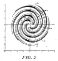
- a first stage scroll pump 18 is mounted within the housing with its inlet region 18a immediately adjacent the inlet port 14a and vacuum inlet 12. It is a high volumetric displacement rate pump. As is best seen in FIG. 2 and 3, the scroll pump 18 is formed by four pairs of nested, spiral-shaped blades (or wraps). Each blade pair includes a stationary blade 19, and an orbiting blade 20. The blades 19 are preferably formed integrally with the housing portion 14b to facilitate heat transfer and to increase the mechanical rigidity and durability of the pump. The blades 20 in turn are preferably formed integrally with a movable plate 22 for the same reasons. The blades 19 and 20 extend axially toward one another and "interleaf" as shown in Figs. 1-3.
- each blade 19 and 20 carries a continuous tip seal 26 of a low-friction, wear resistant, elastomerically energized material such as the seal described with respect to Fig. 7 of U.S. Patent No. 3,994,636 to McCullough et al.
- This seal 26 preferably has an outer layer of a polytetrafluoroethylene based compound with an underlying resilient material that urges the outer layer into a sealing relationship.
- Each blade 19 and 20 extends axially toward the plate 22 and housing portion 14b, respectively, so that there is a light sliding seal at the edge of each blade.
- the tip seals 26 may be omitted. There is then a slight clearance between the free edges of the blades and the facing surfaces.
- the second stage pump 30 transports the gas input from the first stage pump 18 via the channels 28 and chamber 29.
- the pump 30 receives gas at some intermediate pressure, e.g., about 6.5 Pa, and discharges it to atmospheric pressure. It is therefore essential that the pump 30 control backward leakage of gas from an outlet region 30b near its center towards the inlet region 30a at its outer periphery. (As described in more detail below, in each cycle of operation, gas at atmospheric pressure back fills an innermost pocket, and is then squeezed out as the pocket closes.)
- the pump 30 has a single pair of stationary and moving blades 31 and 32, respectively, that spiral in multiple revolutions, more than four as shown, for a total angular distance of more than 1440°.
- Volumes or pockets P9-P16 of working gas entrained in this scroll set are transported in successive cycles of operation as they travel through the pump, here, radially inward along an involute path.
- the gas pockets are also compressed to some extent since the volume of the pockets decreases as they proceed from the inlet to the outlet.
- the resulting internal pressure increase within the second stage pump is, however, negligible when compared to the pressure differential between the inlet and the outlet.
- the pump 30 acts principally through mass transport, not compression. Note that as the radially innermost pocket opens to the outlet it will fill with atmospheric (outlet) pressure gas. Continued orbiting propels this volume of high pressure gas to the outlet and then closes at the outlet in each cycle of operation.
- the axial height of the blades, 31, 32 be comparatively low. As shown, and presently preferred, the axial height is about half that of the first stage blades 19, 20.
- the blades 31, 32 each carry a continuous low friction, wear-resistant tip seal 26 on their free edge. As in the pump 18, the tip seal establishes a sliding seal between the blades and the plate and the opposite housing portion, here 14c.
- the blades 31 and 32 operate with a slight clearance between their opposing surfaces at the point of their closest approach. There should be no actual contact. This clearance is sufficient to substantially contain the gas in the pockets, but avoids blade-to-blade friction, wear and heating.
- a low axial height reduces the cross-sectional area available as a leak path in the clearance seal.
- the precise value for the height cannot be calculated directly with accuracy; it is determined empirically knowing that the displacement rate is linearly proportional to the axial height of the scroll blades and that leakage is a complex function of clearances and angular alignment between the scroll blades, blade height, leakage across the tip seals, and instantaneous pressures and flow regimes within individual scroll pockets.
- the desired value for the axial height will also depend, of course, on the overall size of the pump, its desired operating characteristics, and the blade clearance, both new and after use-induced wear.
- the ultimate controlling design factor for the axial height is whether back leakage is controlled adequately to maintain the desired base pressure in the evacuated system.
- the volumetric displacement rate of the first stage pump 18 exceeds that of the second stage pump 30.
- the first stage I is optimized for volumetric displacement, which is higher than that of any known two-stage, scroll-type vacuum pump; the second stage is optimized to control back leakage, albeit with a smaller volumetric displacement than the first stage. In this way the functions of the stages are separated, optimized, and nevertheless combined in series.
- Figs. 2 and 3 show the blades 19, 20 at two positions during a cycle of operation with the blades superimposed on an x-y grid for ease of reference.
- Figs. 2 and 3 show a nest of four pairs of movable and stationary blades.
- the inlet is at least partially open to all of the blade pairs except the pair 19',20' that have closed at C to block any further inflow of gas from the inlet 18a to the pocket P1.
- the outer outlet end of the Pocket P1 is also closed at C'.
- Continued counter clockwise orbital, not rotational, motion of the movable blade 20' causes the blade 20' to move inwardly away from the immediately adjacent outer stationary blade 19', thus opening the pocket P1 at C'.
- Fig. 3 shows the scroll set of Fig. 2 after the movable blades 20 have orbited at a radius r through 136°, from angular position A to angular position A' about a center of motion at the illustrated x-y coordinates 0,0.
- the direction of orbiting is counter-clockwise at a speed ⁇ .
- a total of eight pockets (two for each blade pair) of somewhat less than 360° angular extent are sequentially closed at the scroll inner ends.
- each trapped pocket is sequentially opened to the outlet 18b. Further orbiting movement results in the reduction of the volume of each pocket to near zero, thereby completing one orbit of the movable plate.
- the volumetric displacement rate of the pump 18 is high, particularly for a dry scroll pump.
- the volumetric displacement rate is calculated to be about two times the best rate heretofore achievable with dry scroll pumps.
- Fig. 4 shows the single pair, multiple revolution scroll set of the second stage pump 30 superimposed on a grid of the same dimension as the grid of Figs. 2 and 3.
- the fluid inlet region 30a extends in an annular band around the outer periphery of the pump 30.
- the fluid enters and is enclosed in two pockets P9 and P10. Because the pump 30 has its movable blade 32 mounted on the opposite side of the plate 22 from the movable blade 20, the direction of orbiting is clockwise as shown, again about a center at the x, y coordinate 0,0 in Fig. 4.
- the orbit radius is, of course, again r. Successive orbits of the blade 32 in successive cycles of operation causes the enclosed masses of gas to travel radially inwardly through the scroll.
- the pump 30 uses a single fixed blade and a single orbiting blade, each with an angular extent of more than four 360° spiral turns.
- a drive 40 for the pumps 18 and 30 is powered by an electric motor 42 connected by a rubber spider coupling 44 to a drive shaft 46 mounted in axially spaced bearings 48, 50.
- Bearing 50 is supported in a collar 52a of a housing 52.
- a snap ring 54 secures the bearing 50 in the collar 52a in cooperation with a seating recess 52b.
- An eccentric, grease-loaded, sealed, ball bearing 56 secured on the end of the drive shift 46 connects to the plate 22 in a central collar 22a of the plate.
- There is a clearance between the drive shaft and the housing portion 14c so the only friction occurs in the bearings and at a dry seal 58 at the interface between the end of the orbiting collar 22a and the facing surface of the housing portion 14c.
- the seal 58 can be of the same material as used for the tip seals 26.
- a fan 60 secured on the drive shaft in the housing 52 produces a flow of cooling air through ports 62 in the housing 52 onto the outer surface of the housing portion 14c.
- a counterweight 64 is formed integral with the fan 60 in order to balance the mass of the plate 22 which is orbiting eccentric with respect to the axis of rotation 46a of the drive shaft.
- a set of metallic fins 66 are mounted in a radial orientation in a recess in the outer face of the housing portion 14c. The fins enhance heat transfer from the pumps 18 and 30 to an air flow produced by the fan.
- the fins 66 also stiffen the housing 14c to resist deformation due to the pressure differential across the housing (at steady state operation, a differential of a few milliTorr to one atmosphere). Deformation is highly undesirable since it varies the scroll wall clearance spacings within the scroll pump 30 which can increase both gas leakage and blade wear. Fins 67 on the housing portion 14b serve the same function as fins 66.
- a set of thrust bearings 68 are dispersed in a circular array between the outer periphery of the plate 22 and the outer, inwardly facing surface of the housing part 14b.
- the thrust bearings are of the type described in U.S. Patent No. 4,259,043.
- Each bearing 68 includes a spherical ball bearing 70 held in two mirror image, circular recesses in the plate and in the housing. Preferably, these recesses are ground to close tolerances in inserts of a wear resistant, hardened material, typically a tool steel.
- the bearings are grease-loaded with a low vapor pressure fluorinated grease such as the product sold by I.E. duPont de Nemours and Co. under the trade designation "Krytox 240AC". Seals 73 prevent grease from exiting the bearings 68.
- the bearings serve two functions. They resist compressive loads produced principally by the differential fluid pressures acting on the plate 22 and they synchronize the relative motion of the scroll blades, that is, they hold the plate 22 in a fixed angular orientation as the eccentric 46 rotates. The rotary motion of the drive shift is thereby faithfully translated into the desired orbital motion.
- the pump 10 is readily assembled and disassembled for replacement of defective or worn parts. Removal of screws 72 allows the housing portions 14b and 14c to be separated axially by pulling the portion 14b away from the portion 14c. The plate 22 is then accessible and can be pulled off the eccentric bearing 56.
- the small crank radius of this invention has a major advantage in that it reduces the velocity of the tip and other seals (since velocity is proportional to the crank radius). This in turn reduces seal wear which results in a longer maintenance interval and less seal wear contamination A regular maintenance interval of 9,000 hours is anticipated.
- the small crank radius also reduces the radial crank force, which it is also proportional to the radius, as well as reducing frictional heating and steady state power consumption.
- a small crank radius allows more revolutions of the second stage blade pair which produces more serially spaced clearance seals and radially spaced tip seals reducing back leakage, whether past the clearance seals or the tip seals.
- the back leakage control provided by this invention allows the complete omission of tip seals in the first stage pump 18. This has clear cost, wear and maintenance advantages.
- crank radius As with the axial height calculation, there is no one correct value for the crank radius.
- the value can be determined empirically from the end performance objectives and the optimization of one or more of the parameters noted above, e.g., wear reduction, power consumption, back leakage control, initial cost reduction, etc.
- Fig. 5 shows an alternative construction for the first stage scroll set where the thrust bearings 68 are arrayed in a circle located inside three nested pairs of spiral blades 19", 20", which, as shown here, extend angularly over one revolution.
- This arrangement uses fewer bearing seals and allows the bearings to oppose axial forces more directly. This arrangement provides less resistance to moments tending to produce wobbling of the plate.
- Three inlet ports 14a' are shown at the termination of the three innermost pockets.
- a circular seal 90 of the same material as the seals 26 and 58 surrounds the bearings 68.
- the invention can operate with plural orbiting plates, one for each stage, and with a different number of nested scrolls, e.g., five, and angular extent of blades (e.g., 340°-380°) in the first stage, but with certain trade-offs.
- the preferred embodiment uses air cooling exclusively, this invention can be used with liquid lubricants and coolants, although with the attendant contamination problems noted above, as well as the cost of providing systems, seals, and the like to support liquid cooling and/or lubricants.
- the invention has been described with a common central eccentric drive, it is possible to utilize the features and advantages of this invention with other known eccentric drives such as multiple peripheral cranks.
Landscapes
- Engineering & Computer Science (AREA)
- Mechanical Engineering (AREA)
- General Engineering & Computer Science (AREA)
- Rotary Pumps (AREA)
- Applications Or Details Of Rotary Compressors (AREA)
Applications Claiming Priority (2)
| Application Number | Priority Date | Filing Date | Title |
|---|---|---|---|
| US484145 | 1995-06-07 | ||
| US08/484,145 US5616015A (en) | 1995-06-07 | 1995-06-07 | High displacement rate, scroll-type, fluid handling apparatus |
Publications (3)
| Publication Number | Publication Date |
|---|---|
| EP0747596A2 true EP0747596A2 (fr) | 1996-12-11 |
| EP0747596A3 EP0747596A3 (fr) | 1998-01-07 |
| EP0747596B1 EP0747596B1 (fr) | 2002-11-20 |
Family
ID=23922950
Family Applications (1)
| Application Number | Title | Priority Date | Filing Date |
|---|---|---|---|
| EP96304064A Expired - Lifetime EP0747596B1 (fr) | 1995-06-07 | 1996-06-04 | Appareil de déplacement de fluide à spirales |
Country Status (4)
| Country | Link |
|---|---|
| US (2) | US5616015A (fr) |
| EP (1) | EP0747596B1 (fr) |
| JP (1) | JPH09112446A (fr) |
| DE (1) | DE69624867T2 (fr) |
Cited By (4)
| Publication number | Priority date | Publication date | Assignee | Title |
|---|---|---|---|---|
| WO1998037327A1 (fr) * | 1997-02-25 | 1998-08-27 | Varian Associates, Inc. | Dispositif de pompe a depression a deux etages |
| BE1015121A3 (fr) * | 2001-09-27 | 2004-10-05 | Anest Iwata Corp | Machine a fluide du type a volutes. |
| CN104500395A (zh) * | 2014-12-12 | 2015-04-08 | 沙无埃 | 涡旋压缩机 |
| CN106382220A (zh) * | 2015-07-26 | 2017-02-08 | 熵零股份有限公司 | 涡旋流体机构 |
Families Citing this family (61)
| Publication number | Priority date | Publication date | Assignee | Title |
|---|---|---|---|---|
| US5616015A (en) * | 1995-06-07 | 1997-04-01 | Varian Associates, Inc. | High displacement rate, scroll-type, fluid handling apparatus |
| KR100191728B1 (ko) * | 1996-12-18 | 1999-06-15 | 구자홍 | 스크롤 펌프의 펌핑구조 |
| US5951270A (en) * | 1997-06-03 | 1999-09-14 | Tecumseh Products Company | Non-contiguous thrust bearing interface for a scroll compressor |
| US6158989A (en) | 1997-12-15 | 2000-12-12 | Scroll Technologies | Scroll compressor with integral outer housing and fixed scroll member |
| US6068459A (en) | 1998-02-19 | 2000-05-30 | Varian, Inc. | Tip seal for scroll-type vacuum pump |
| WO2000006906A1 (fr) | 1998-07-30 | 2000-02-10 | Varian, Inc. | Pompe a vide de type a spirale |
| US6511308B2 (en) * | 1998-09-28 | 2003-01-28 | Air Squared, Inc. | Scroll vacuum pump with improved performance |
| WO2001003606A2 (fr) * | 1999-07-08 | 2001-01-18 | Alsius Corporation | Ameliorations du fonctionnement de catheters refrigerants |
| DE19945241A1 (de) * | 1999-09-21 | 2001-04-05 | Messer Griesheim Gmbh | Verfahren zur schonenden Verdichtung von hochreinen Gasen |
| US6499977B2 (en) | 2000-04-24 | 2002-12-31 | Scroll Technologies | Scroll compressor with integral outer housing and a fixed scroll member |
| JP4419039B2 (ja) * | 2001-02-08 | 2010-02-24 | 株式会社豊田自動織機 | 燃料電池用スクロール式圧縮機 |
| JP2003227476A (ja) * | 2002-02-05 | 2003-08-15 | Matsushita Electric Ind Co Ltd | 空気供給装置 |
| US6758659B2 (en) * | 2002-04-11 | 2004-07-06 | Shimao Ni | Scroll type fluid displacement apparatus with fully compliant floating scrolls |
| DE10225774C1 (de) * | 2002-06-10 | 2003-12-11 | Vacuubrand Gmbh & Co Kg | Vakuumpumpe |
| CN1761848A (zh) * | 2003-01-24 | 2006-04-19 | 布里斯托尔压缩机公司 | 用于制冷系统中分级容量调制的系统和方法 |
| DE20307911U1 (de) | 2003-05-19 | 2003-09-04 | ILMVAC GmbH, 98693 Ilmenau | Scrollpumpe |
| JP4658245B2 (ja) * | 2003-05-29 | 2011-03-23 | 株式会社日立製作所 | スクロール式流体機械 |
| US20050063850A1 (en) * | 2003-09-18 | 2005-03-24 | Liepert Anthony G. | Scroll pump using isolation bellows and synchronization mechanism |
| US6884047B1 (en) * | 2003-10-20 | 2005-04-26 | Varian, Inc. | Compact scroll pump |
| US6764288B1 (en) | 2003-11-06 | 2004-07-20 | Varian, Inc. | Two stage scroll vacuum pump |
| US7261528B2 (en) * | 2004-03-30 | 2007-08-28 | Varian, Inc. | Scroll pump with load bearing synchronization device |
| RU2287720C2 (ru) * | 2004-05-12 | 2006-11-20 | Закрытое акционерное общество "Научно-исследовательский институт центробежных и роторных компрессоров им. В.Б. Шнеппа" | Спиральная машина |
| US7189066B2 (en) * | 2004-05-14 | 2007-03-13 | Varian, Inc. | Light gas vacuum pumping system |
| US7244113B2 (en) * | 2004-10-07 | 2007-07-17 | Varian, Inc. | Scroll pump with controlled axial thermal expansion |
| JP4732446B2 (ja) * | 2005-03-28 | 2011-07-27 | 三菱電機株式会社 | スクロール圧縮機 |
| DE102005042451B4 (de) * | 2005-09-06 | 2007-07-26 | Vacuubrand Gmbh + Co Kg | Vakuumpumpvorrichtung |
| JP4629546B2 (ja) * | 2005-09-30 | 2011-02-09 | アネスト岩田株式会社 | スクロール流体機械 |
| JP4709016B2 (ja) * | 2006-01-12 | 2011-06-22 | アネスト岩田株式会社 | 複合圧縮機 |
| US7467933B2 (en) * | 2006-01-26 | 2008-12-23 | Scroll Laboratories, Inc. | Scroll-type fluid displacement apparatus with fully compliant floating scrolls |
| US8523544B2 (en) | 2010-04-16 | 2013-09-03 | Air Squared, Inc. | Three stage scroll vacuum pump |
| US10221852B2 (en) * | 2006-02-14 | 2019-03-05 | Air Squared, Inc. | Multi stage scroll vacuum pumps and related scroll devices |
| US10683865B2 (en) | 2006-02-14 | 2020-06-16 | Air Squared, Inc. | Scroll type device incorporating spinning or co-rotating scrolls |
| US8177534B2 (en) | 2008-10-30 | 2012-05-15 | Advanced Scroll Technologies (Hangzhou), Inc. | Scroll-type fluid displacement apparatus with improved cooling system |
| GB2472635A (en) * | 2009-08-14 | 2011-02-16 | Edwards Ltd | Seal-less tip scroll booster pump for spectrometer |
| US8622724B2 (en) * | 2009-09-25 | 2014-01-07 | Agilent Technologies, Inc. | Scroll pump with isolation barrier |
| JP2011080366A (ja) * | 2009-10-02 | 2011-04-21 | Anest Iwata Corp | モータ直結型圧縮機ユニット |
| US11047389B2 (en) | 2010-04-16 | 2021-06-29 | Air Squared, Inc. | Multi-stage scroll vacuum pumps and related scroll devices |
| GB201007028D0 (en) * | 2010-04-28 | 2010-06-09 | Edwards Ltd | Scroll pump |
| JP5421886B2 (ja) * | 2010-09-30 | 2014-02-19 | アネスト岩田株式会社 | スクロール流体機械 |
| CN102817840B (zh) * | 2011-06-07 | 2014-08-27 | 思科涡旋科技(杭州)有限公司 | 一种带有绕动式推力轴承的涡卷式容积位移装置 |
| US20130232975A1 (en) | 2011-08-09 | 2013-09-12 | Robert W. Saffer | Compact energy cycle construction utilizing some combination of a scroll type expander, pump, and compressor for operating according to a rankine, an organic rankine, heat pump, or combined organic rankine and heat pump cycle |
| US8961160B2 (en) | 2013-03-29 | 2015-02-24 | Agilent Technologies, Inc. | Scroll pump having separable orbiting plate scroll and method of replacing tip seal |
| US20150078927A1 (en) * | 2013-09-13 | 2015-03-19 | Agilent Technologies, Inc. | Multi-Stage Pump Having Reverse Bypass Circuit |
| JP2016084717A (ja) * | 2014-10-23 | 2016-05-19 | 株式会社日本自動車部品総合研究所 | スクロール型圧縮機 |
| CN104612968B (zh) * | 2014-12-19 | 2016-09-28 | 东北大学 | 一种双级涡旋干式真空泵 |
| US10508543B2 (en) | 2015-05-07 | 2019-12-17 | Air Squared, Inc. | Scroll device having a pressure plate |
| GB2548607B (en) * | 2016-03-23 | 2020-05-06 | Edwards Ltd | Scroll pump tip sealing |
| JP6661520B2 (ja) * | 2016-11-30 | 2020-03-11 | 三菱重工業株式会社 | スクロール圧縮機とその製造方法 |
| US10865793B2 (en) | 2016-12-06 | 2020-12-15 | Air Squared, Inc. | Scroll type device having liquid cooling through idler shafts |
| CN107084134A (zh) * | 2017-06-26 | 2017-08-22 | 湖北维斯曼新能源科技有限公司 | 新型两级压缩涡旋式空气压缩机 |
| EP3788262B1 (fr) | 2018-05-04 | 2024-11-20 | Air Squared, Inc. | Refroidissement par liquide de compresseur, de détendeur ou de pompe à vide à volute fixe et orbitale |
| US11067080B2 (en) | 2018-07-17 | 2021-07-20 | Air Squared, Inc. | Low cost scroll compressor or vacuum pump |
| US20200025199A1 (en) | 2018-07-17 | 2020-01-23 | Air Squared, Inc. | Dual drive co-rotating spinning scroll compressor or expander |
| US11530703B2 (en) | 2018-07-18 | 2022-12-20 | Air Squared, Inc. | Orbiting scroll device lubrication |
| JP7212926B2 (ja) * | 2018-11-08 | 2023-01-26 | 有限会社スクロール技研 | スクロール型真空ポンプ |
| CN110080970B (zh) * | 2019-06-03 | 2021-07-20 | 山东鲁化森萱新材料有限公司 | 一种聚甲醛真空挤出机 |
| US11473572B2 (en) | 2019-06-25 | 2022-10-18 | Air Squared, Inc. | Aftercooler for cooling compressed working fluid |
| US11898557B2 (en) | 2020-11-30 | 2024-02-13 | Air Squared, Inc. | Liquid cooling of a scroll type compressor with liquid supply through the crankshaft |
| US11885328B2 (en) | 2021-07-19 | 2024-01-30 | Air Squared, Inc. | Scroll device with an integrated cooling loop |
| US20250020137A1 (en) * | 2023-06-09 | 2025-01-16 | Scott Fetzer/Powerex-Iwata Air Technology Inc. | Cooling attachment system for compressor motor assembly |
| CN120367797A (zh) * | 2024-01-23 | 2025-07-25 | 罗伯特·博世有限公司 | 涡旋式压缩机 |
Family Cites Families (23)
| Publication number | Priority date | Publication date | Assignee | Title |
|---|---|---|---|---|
| US801182A (en) * | 1905-06-26 | 1905-10-03 | Leon Creux | Rotary engine. |
| GB220296A (en) * | 1923-08-08 | 1925-01-08 | Luigi Nordi | Improvements in or relating to fluid pumps and the like |
| US2494100A (en) * | 1944-03-27 | 1950-01-10 | Mikulasek John | Displacement mechanism |
| US2475247A (en) * | 1944-05-22 | 1949-07-05 | Mikulasek John | Planetary piston fluid displacement mechanism |
| FR2153129B2 (fr) * | 1971-06-01 | 1974-01-04 | Vulliez Paul | |
| CH586348A5 (fr) * | 1975-02-07 | 1977-03-31 | Aginfor Ag | |
| US4259043A (en) * | 1977-06-17 | 1981-03-31 | Arthur D. Little, Inc. | Thrust bearing/coupling component for orbiting scroll-type machinery and scroll-type machinery incorporating the same |
| US4141677A (en) * | 1977-08-15 | 1979-02-27 | Ingersoll-Rand Company | Scroll-type two stage positive fluid-displacement apparatus with intercooler |
| US4192152A (en) * | 1978-04-14 | 1980-03-11 | Arthur D. Little, Inc. | Scroll-type fluid displacement apparatus with peripheral drive |
| JPS5728890A (en) * | 1980-07-30 | 1982-02-16 | Hitachi Ltd | Non lubricating scroll type fluid machine |
| US4523897A (en) * | 1982-06-11 | 1985-06-18 | Robinair Division | Two stage vacuum pump |
| US4477238A (en) * | 1983-02-23 | 1984-10-16 | Sanden Corporation | Scroll type compressor with wrap portions of different axial heights |
| JPS61152984A (ja) * | 1984-12-26 | 1986-07-11 | Nippon Soken Inc | スクロ−ル型圧縮機 |
| CH667497A5 (de) * | 1985-04-26 | 1988-10-14 | Bbc Brown Boveri & Cie | Rotationskolben-verdraengungsarbeitsmaschine. |
| DE3525933A1 (de) * | 1985-07-19 | 1987-01-29 | Bock Gmbh & Co Kaeltemaschinen | Spiralverdichter |
| JPS631782A (ja) * | 1986-06-20 | 1988-01-06 | Tokico Ltd | スクロ−ル式真空ポンプ |
| CH673874A5 (fr) * | 1987-03-24 | 1990-04-12 | Bbc Brown Boveri & Cie | |
| CH675896A5 (fr) * | 1988-07-20 | 1990-11-15 | Aginfor Ag | |
| JP2707296B2 (ja) * | 1988-11-19 | 1998-01-28 | トキコ株式会社 | スクロール式流体機械 |
| US5258046A (en) * | 1991-02-13 | 1993-11-02 | Iwata Air Compressor Mfg. Co., Ltd. | Scroll-type fluid machinery with seals for the discharge port and wraps |
| JP2718295B2 (ja) * | 1991-08-30 | 1998-02-25 | ダイキン工業株式会社 | スクロール圧縮機 |
| JPH06101666A (ja) * | 1992-09-09 | 1994-04-12 | Hitachi Ltd | スクロール圧縮機 |
| US5616015A (en) * | 1995-06-07 | 1997-04-01 | Varian Associates, Inc. | High displacement rate, scroll-type, fluid handling apparatus |
-
1995
- 1995-06-07 US US08/484,145 patent/US5616015A/en not_active Expired - Lifetime
-
1996
- 1996-06-04 DE DE69624867T patent/DE69624867T2/de not_active Expired - Lifetime
- 1996-06-04 JP JP8162480A patent/JPH09112446A/ja active Pending
- 1996-06-04 EP EP96304064A patent/EP0747596B1/fr not_active Expired - Lifetime
-
1997
- 1997-02-13 US US08/800,909 patent/US5855473A/en not_active Expired - Lifetime
Cited By (4)
| Publication number | Priority date | Publication date | Assignee | Title |
|---|---|---|---|---|
| WO1998037327A1 (fr) * | 1997-02-25 | 1998-08-27 | Varian Associates, Inc. | Dispositif de pompe a depression a deux etages |
| BE1015121A3 (fr) * | 2001-09-27 | 2004-10-05 | Anest Iwata Corp | Machine a fluide du type a volutes. |
| CN104500395A (zh) * | 2014-12-12 | 2015-04-08 | 沙无埃 | 涡旋压缩机 |
| CN106382220A (zh) * | 2015-07-26 | 2017-02-08 | 熵零股份有限公司 | 涡旋流体机构 |
Also Published As
| Publication number | Publication date |
|---|---|
| EP0747596A3 (fr) | 1998-01-07 |
| DE69624867T2 (de) | 2003-07-03 |
| US5616015A (en) | 1997-04-01 |
| DE69624867D1 (de) | 2003-01-02 |
| JPH09112446A (ja) | 1997-05-02 |
| US5855473A (en) | 1999-01-05 |
| EP0747596B1 (fr) | 2002-11-20 |
Similar Documents
| Publication | Publication Date | Title |
|---|---|---|
| EP0747596B1 (fr) | Appareil de déplacement de fluide à spirales | |
| US5466134A (en) | Scroll compressor having idler cranks and strengthening and heat dissipating ribs | |
| KR100326852B1 (ko) | 스크롤 콤프레사의 축류 컴플라이언스를 위한 계단식 중간 압축실 | |
| US4389171A (en) | Gas compressor of the scroll type having reduced starting torque | |
| JPS60190691A (ja) | 流体圧縮用スクロール機 | |
| EP0143526A2 (fr) | Compresseur avec espace de travail en spirale | |
| EP2361352A2 (fr) | Appareil de déplacement de fluide de type à volute ayant un meilleur système de refroidissement | |
| JPH02102385A (ja) | 排気装置 | |
| WO1996000852A1 (fr) | Machine a deplacement de fluide du type a ailettes sans contact comprenant un ensemble separateur de lubrifiant et reservoir | |
| US5478210A (en) | Multi-stage vacuum pump | |
| US5947694A (en) | Scroll-type vacuum pumping apparatus | |
| EP0767866A1 (fr) | Machine a deplacement de fluide, selon la technologie a pales sans contact et ensemble de guide-pales renforce | |
| CN107893758B (zh) | 涡旋压缩机及具有其的空调器 | |
| JPS62210278A (ja) | スクロ−ル真空ポンプ | |
| US7186098B2 (en) | Eccentric pump and method for operation of said pump | |
| US6213742B1 (en) | Scroll-type fluid mover having an eccentric shaft radially aligned with a volute portion | |
| US7726960B2 (en) | Twin-plate rotary compressor | |
| CN114320905A (zh) | 一种涡旋压缩机结构 | |
| US8998597B2 (en) | Compressor, engine or pump with a piston translating along a circular path | |
| JP2796811B2 (ja) | スクロール式流体機械 | |
| JPS6170194A (ja) | スクロ−ル流体機械 | |
| JPH03145592A (ja) | コンプレッサー | |
| JPH09268983A (ja) | スクロール式流体機械 | |
| KR102361320B1 (ko) | 2단 압축구조를 가지는 로터리 압축기 | |
| JP2751318B2 (ja) | スクロール型圧縮機 |
Legal Events
| Date | Code | Title | Description |
|---|---|---|---|
| PUAI | Public reference made under article 153(3) epc to a published international application that has entered the european phase |
Free format text: ORIGINAL CODE: 0009012 |
|
| AK | Designated contracting states |
Kind code of ref document: A2 Designated state(s): DE GB |
|
| PUAL | Search report despatched |
Free format text: ORIGINAL CODE: 0009013 |
|
| AK | Designated contracting states |
Kind code of ref document: A3 Designated state(s): DE GB |
|
| 17P | Request for examination filed |
Effective date: 19980213 |
|
| RAP1 | Party data changed (applicant data changed or rights of an application transferred) |
Owner name: VARIAN, INC. |
|
| 17Q | First examination report despatched |
Effective date: 20010226 |
|
| GRAG | Despatch of communication of intention to grant |
Free format text: ORIGINAL CODE: EPIDOS AGRA |
|
| GRAG | Despatch of communication of intention to grant |
Free format text: ORIGINAL CODE: EPIDOS AGRA |
|
| GRAH | Despatch of communication of intention to grant a patent |
Free format text: ORIGINAL CODE: EPIDOS IGRA |
|
| GRAG | Despatch of communication of intention to grant |
Free format text: ORIGINAL CODE: EPIDOS AGRA |
|
| GRAH | Despatch of communication of intention to grant a patent |
Free format text: ORIGINAL CODE: EPIDOS IGRA |
|
| GRAH | Despatch of communication of intention to grant a patent |
Free format text: ORIGINAL CODE: EPIDOS IGRA |
|
| GRAA | (expected) grant |
Free format text: ORIGINAL CODE: 0009210 |
|
| AK | Designated contracting states |
Kind code of ref document: B1 Designated state(s): DE GB |
|
| REG | Reference to a national code |
Ref country code: GB Ref legal event code: FG4D |
|
| REF | Corresponds to: |
Ref document number: 69624867 Country of ref document: DE Date of ref document: 20030102 |
|
| PLBE | No opposition filed within time limit |
Free format text: ORIGINAL CODE: 0009261 |
|
| STAA | Information on the status of an ep patent application or granted ep patent |
Free format text: STATUS: NO OPPOSITION FILED WITHIN TIME LIMIT |
|
| 26N | No opposition filed |
Effective date: 20030821 |
|
| REG | Reference to a national code |
Ref country code: GB Ref legal event code: 732E Free format text: REGISTERED BETWEEN 20110324 AND 20110330 |
|
| PGFP | Annual fee paid to national office [announced via postgrant information from national office to epo] |
Ref country code: GB Payment date: 20110601 Year of fee payment: 16 |
|
| REG | Reference to a national code |
Ref country code: DE Ref legal event code: R082 Ref document number: 69624867 Country of ref document: DE Representative=s name: KAHLER, KAECK & MOLLEKOPF, DE |
|
| REG | Reference to a national code |
Ref country code: DE Ref legal event code: R082 Ref document number: 69624867 Country of ref document: DE Representative=s name: BARTH, DANIEL, DIPL.-ING., DE Effective date: 20111130 Ref country code: DE Ref legal event code: R081 Ref document number: 69624867 Country of ref document: DE Owner name: AGILENT TECHNOLOGIES INC., SANTA CLARA, US Free format text: FORMER OWNER: VARIAN, INC., PALO ALTO, CALIF., US Effective date: 20111130 Ref country code: DE Ref legal event code: R081 Ref document number: 69624867 Country of ref document: DE Owner name: AGILENT TECHNOLOGIES INC., US Free format text: FORMER OWNER: VARIAN, INC., PALO ALTO, US Effective date: 20111130 |
|
| GBPC | Gb: european patent ceased through non-payment of renewal fee |
Effective date: 20120604 |
|
| REG | Reference to a national code |
Ref country code: DE Ref legal event code: R082 Ref document number: 69624867 Country of ref document: DE Representative=s name: BARTH, DANIEL, DIPL.-ING., DE |
|
| PG25 | Lapsed in a contracting state [announced via postgrant information from national office to epo] |
Ref country code: GB Free format text: LAPSE BECAUSE OF NON-PAYMENT OF DUE FEES Effective date: 20120604 |
|
| PGFP | Annual fee paid to national office [announced via postgrant information from national office to epo] |
Ref country code: DE Payment date: 20150527 Year of fee payment: 20 |
|
| REG | Reference to a national code |
Ref country code: DE Ref legal event code: R071 Ref document number: 69624867 Country of ref document: DE |