EP0747682B1 - Vorrichtung zur Temperaturmessung - Google Patents
Vorrichtung zur Temperaturmessung Download PDFInfo
- Publication number
- EP0747682B1 EP0747682B1 EP95113225A EP95113225A EP0747682B1 EP 0747682 B1 EP0747682 B1 EP 0747682B1 EP 95113225 A EP95113225 A EP 95113225A EP 95113225 A EP95113225 A EP 95113225A EP 0747682 B1 EP0747682 B1 EP 0747682B1
- Authority
- EP
- European Patent Office
- Prior art keywords
- temperature
- type thermometer
- noncontact
- measurement object
- measuring apparatus
- Prior art date
- Legal status (The legal status is an assumption and is not a legal conclusion. Google has not performed a legal analysis and makes no representation as to the accuracy of the status listed.)
- Expired - Lifetime
Links
- 238000009529 body temperature measurement Methods 0.000 claims description 42
- 230000005855 radiation Effects 0.000 claims description 17
- 238000005259 measurement Methods 0.000 claims description 13
- 239000004973 liquid crystal related substance Substances 0.000 description 5
- 239000000463 material Substances 0.000 description 4
- 238000000034 method Methods 0.000 description 4
- 238000010586 diagram Methods 0.000 description 2
- 230000003287 optical effect Effects 0.000 description 2
- 238000002310 reflectometry Methods 0.000 description 1
- 238000002834 transmittance Methods 0.000 description 1
Images


Classifications
-
- G—PHYSICS
- G01—MEASURING; TESTING
- G01J—MEASUREMENT OF INTENSITY, VELOCITY, SPECTRAL CONTENT, POLARISATION, PHASE OR PULSE CHARACTERISTICS OF INFRARED, VISIBLE OR ULTRAVIOLET LIGHT; COLORIMETRY; RADIATION PYROMETRY
- G01J5/00—Radiation pyrometry, e.g. infrared or optical thermometry
- G01J5/0003—Radiation pyrometry, e.g. infrared or optical thermometry for sensing the radiant heat transfer of samples, e.g. emittance meter
Definitions
- the present invention relates to an improved temperature measuring apparatus using a noncontact-type thermometer, particularly to a temperature measuring apparatus capable of automatically correcting an error of a measured value due to a difference of the emissivity, reflectivity, or transmittance of a temperature measurement object.
- thermometer for measuring the surface temperature of an object is roughly divided into the following two types.
- One is a contact-type thermometer which measures the temperature of an object by bringing the temperature sensing section of the thermometer into contact with the surface of the object and the other is a noncontact-type thermometer which measures the temperature of an object by detecting infrared energy emitted from the surface of the object.
- the noncontact-type thermometer has more advantages than the contact-type thermometer, it is recently used at various places.
- the above advantages include that heat is only slightly transferred to and from the surface of a temperature measurement object, the surface of the temperature measurement object is not damaged, and the response speed is high.
- the noncontact-type thermometer has the following problems in view of its measuring theory. That is, ⁇ 1> for a value measured by the noncontacttype thermometer, the quantity of infrared energy emitted from the surface of a temperature measurement object must be corrected depending on the material or the surface state of the object because the quantity of infrared energy depends on the material or the surface state of the object.
- a measured value includes an error because infrared energy coming from places other than the surface of the temperature measurement object in addition to the infrared energy emitted from the surface of the object reflects on the surface of the object and it is detected.
- correction values (emissivities) classified in accordance with the material or the surface state of the object are selected out of a list in a document, set to the noncontact-type thermometer correction device as parameters, and measured.
- the correction values in the document are experimentally obtained. Thereafter, it is uncertain whether the values are suitable for the material or the surface state of an actual temperature measurement object and thus, a measured value easily includes an error depending on a selected parameter.
- a value displayed by the noncontact-type thermometer including an error is a true value.
- temperature can also accurately be measured by the noncontact-type thermometer by simultaneously using the contact-type thermometer and thereby, manually correcting an error in accordance with the temperature of a temperature measurement object measured by the contact-type thermometer.
- the European Patent Application EP 0 442 351 A1 discloses such a non-contact infrared temperature sensing system.
- the sensor of this system comprises an additional temperature sensor, which measures the temperature of the non-contact infrared temperature sensing system itself, and the system intends a contact-thermometer to measure the temperature of the surface of the object whose temperature is to be determined and, therefore, to determine the emissivity-factor.
- a measured value includes another error because infrared energy coming from places other than the surface of the temperature measurement object in addition to the infrared energy emitted from the surface of the object reflects on the surface of the object and is, therefore, detected, is totally ignored by this sensing system.
- the present invention is made to solve the above problems and its object is to provide a temperature measuring apparatus for automatically calculating a correction multiplier for correcting data measured by a noncontact-type thermometer to a true value by using data measured by a contact-type thermometer as a true value in accordance with the data measured by the contact- and noncontact-type thermometers, correcting the data measured by the noncontact-type thermometer in accordance with the correction multiplier, and always accurately measuring temperature by the noncontact method. It is another object of the present invention to provide a temperature measuring apparatus having a function for verifying whether the measurement environment is proper or not in accordance with a correction multiplier.
- thermometer it is possible to properly select a sensor out of various sensors including a thermocouple and a thermistor as the contact-type thermometer in accordance with a purpose.
- thermocouple As for the noncontact-type thermometer, it is preferable to use a thermopile or a thermistor bolometer as its infrared detector.
- the display means can use aurally recognizing means in addition to visually recognizing means.
- a measurer can correct an error of data measured by a noncontact-type thermometer set separately from a temperature measurement object in accordance with a temperature measured by bringing the sensor section of a contact-type thermometer into contact with the surface of the temperature measurement object and recognize an error correction data, that is, a correction multiplier through a display unit.
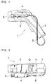
- the temperature measuring apparatus 1 of this embodiment is provided with a noncontact-type thermometer 3 set in a body case 2, a sensor section 5 supported by a holder 4 laterally protruded from the body case 2, and a contact-type temperature measuring section set in the body case 2 is the same as the noncontact-type thermometer 3.
- the sensor section 5 is connected via a cable 6 to a circuit of the contact-type temperature measuring section in the body case 2.
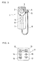
- Part of the body case 2 serves as a grip 7 on which a laser switch 8 for emitting a pointing laser beam and a hold switch 9 for temporarily stopping display and determining correction data are set, as shown in Fig. 3.
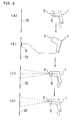
- a switch panel 11 shown in Fig. 4 is set below a liquid crystal display section 10.
- the switch panel 11 is provided with an ON switch 12 for turning on a power supply, an OFF switch 13 for turning off the power supply, a CAL switch 14 for setting a correction measurement mode or returning the mode to the current state, a MODE switch 15 for switching between contact- and noncontact-type measurement modes, and a correction multiplier setting switches 16 and 17 for setting the value of correction multiplier A ⁇ .
- FIG. 5 A schematic view of the circuit configuration set in the body case 2 is shown in Fig. 5 in the form of a block diagram.
- Measured data for the output Vd of a detector e.g. thermopile
- a noncontact temperature measuring section 18 an optical section for detecting infrared radiation
- Td of the detector is sent to a correction multiplier calculating section 19.
- Measured data inputted to a contact-type temperature measuring section 20 from the sensor section 5 is converted to a temperature value T TC and sent to the correction multiplier calculating section 19.
- the correction multiplier A ⁇ is calculated through the following steps in accordance with the received data.
- the temperature Td of the detector sent from the noncontact temperature measuring section 18 and the temperature value (temperature of the temperature measurement object) T TC sent from the contact-type temperature measuring section 20 are converted to an infrared energy quantity corresponding to each temperature value.
- Temperature of temperature measurement object T TC ⁇ Infrared energy quantity: L TC
- the correction multiplier A ⁇ is obtained from the following expression in accordance with the converted energy quantities.
- a ⁇ Vd/(L TC - Ld)
- the temperature Td of the detector is converted to an infrared energy quantity.
- the infrared energy quantity L IR is obtained from the following expression in accordance with the converted infrared energy quantity.
- L IR Vd/A ⁇ + Ld
- the infrared energy quantity L IR obtained from the above expression is converted to a temperature to obtain the correction value T IR of the noncontact-type thermometer 3.
- Infrared energy quantity L IR ⁇ Correction value of noncontact-type thermometer 3: T IR .
- the correction value T IR thus obtained is displayed on the liquid crystal display section 10 together with the correction multiplier A ⁇ and the value measured by the contact-type thermometer used to calculate the correction multiplier A ⁇ .
- the mode is changed to the calibration mode under the state shown in Fig. 6(a) and the surface temperature of a temperature measurement object 22 with which the sensor section 5 contacts under the state shown in Fig. 6(b). Then, temperature is measured by the noncontact-type thermometer 3 under the state shown in Fig. 6(c) to determine the infrared energy quantity emitted from the surface of the temperature measurement object 22, the correction multiplier A ⁇ is calculated under the state shown in Fig. 6(d), and temperature after converted by the correction multiplier A ⁇ is displayed.
- S 2 shows the display of the mode for performing measurements by using the noncontact-type thermometer 3 and S 3 shows the display of the mode for performing measurement by using a contact-type thermometer.
- S 3 shows the display of the mode for performing measurement by using a contact-type thermometer.
- a temperature value measured by the noncontact-type thermometer 3 under the condition for deciding the correction multiplier A ⁇ is determined as shown by S 5 in Fig. 7.
- the temperature measuring apparatus of the present invention makes it possible to correct an error of a value measured by a noncontact-type thermometer set separately from a temperature measurement object in accordance with the temperature measured by bringing the sensor section of a contact-type thermometer into contact with the surface of the temperature measurement object and moreover, the temperature measuring apparatus allows a measurer to recognize the error correction data, that is, a correction multiplier by a display unit.
- the temperature measuring apparatus makes it possible to set a correction multiplier including the external heat radiation.
- the temperature measuring apparatus displays for recognition by the measurer that correction has not been made.
- thermometer realizing highly accurate noncontact-type temperature measurement by combining advantages of a noncontact-type thermometer with those of a contact-type thermometer.
Landscapes
- Physics & Mathematics (AREA)
- General Physics & Mathematics (AREA)
- Spectroscopy & Molecular Physics (AREA)
- Radiation Pyrometers (AREA)
Claims (8)
- Temperaturmeßvorrichtung (1) mit einem berührungsfreien Thermometer (3) zur Messung der Temperatur eines Temperaturmeßgegenstandes (22) auf der Basis der Übertragung von Wärmestrahlung zu dem Temperaturmeßgegenstand (22) und von diesem, mit einem Berührungsthermometer (5) zum Messen der Temperatur des Temperaturmeßgegenstandes (22), indem ein Sensorabschnitt (5) in Kontakt mit der Oberfläche des Temperaturmeßgegenstandes (22) gebracht wird, einer arithmetischen Einrichtung zum Berechnen eines Korrekturfaktors für die Korrektur eines Fehlers der Daten, die durch das berührungsfreie Thermometer (3) gemessen wird, und zwar entsprechend den durch das berührungsfreie Thermometer (3) gemessenen Daten sowie eines Wertes, der durch das Berührungsthermometer (5) gemessen wurde, und darüberhinaus Berechnen eines Korrekturwertes durch Korrigieren der durch das berührungsfreie Thermometer gemessenen Daten entsprechend dem Korrekturfaktor, und mit einer Anzeigeeinrichtung zum Anzeigen des gemessenen Wertes und des Korrekturwertes, wobei ein Korrekturfaktor eingestellt wird, der die Wirkung externer Wärmestrahlung einschließt, welche als Störfaktor zusätzlich zu der Wärmestrahlung zwischen dem Temperaturmeßgegenstand und dem berührungsfreien Thermometer (3) wirkt.
- Temperaturmeßvorrichtung nach Anspruch 1, wobei der Sensorabschnitt (5) des Berührungsthermometers (5) abnehmbar durch einen Halter (4) getragen wird, der an einer Hülle (2) des Hauptteiles der Temperaturmeßvorrichtung (1) sitzt, und wobei das Berührungsthermometer (5) und das berührungsfreie Thermometer (3) in die Umhüllung (2) des Hauptteiles integriert eingebaut sind.
- Temperaturmeßvorrichtung (1) nach Anspruch 1, wobei die Anzeigeeinrichtung anzeigt, daß ein genauer Korrekturwert nicht bestimmt wurde, falls die Wärmestrahlung zwischen dem Temperaturmeßgegenstand (22) und dem berührungsfreien Thermometer (3) kleiner ist als ein vorbestimmter Wert.
- Temperaturmeßvorrichtung (1) nach Anspruch 1, wobei es möglich ist zu bestätigen bzw. festzustellen, daß ein Fehler in den gemessenen Temperaturdaten des Temperaturmeßgegenstandes (22) enthalten ist, wenn externe Wärmestrahlung die Wärmestrahlung zwischen dem Temperaturmeßgegenstand (22) und dem berührungsfreien Thermometer (3) beeinflußt.
- Temperaturmeßvorrichtung (1) nach Anspruch 1, wobei ein Korrekturfaktor für die Daten des berührungsfreien Thermometers (3), falls eine Entscheidung über den Korrekturfaktor getroffen wird, sowie ein Wert, der durch das berührungsfreie Thermometer (3) während der Messung angezeigt wird, auf demselben Bildschirm dargestellt werden.
- Temperaturmeßvorrichtung (1) nach Anspruch 1, wobei das Berührungsthermometer (5) einen Thermoelement-Oberflächentemperatursensor verwendet und das Thermometer (3) vom berührungsfreien Typ einen Wärmedetektor verwendet.
- Temperaturmeßvorrichtung (1) nach Anspruch 1, wobei die Anzeigeeinrichtung anzeigt, welches der Thermometer, nämlich das Berührungsthermometer (5) und das berührungsfreie Thermometer (3) für die Messung entsprechend den Meßbedingungen besser geeignet ist, wobei das Berührungsthermometer (5) dann geeignet ist, wenn die Wärmestrahlung zwischen dem Temperaturmeßgegenstand (22) und dem berührungsfreien Thermometer (3) kleiner als ein vorbestimmter Wert ist, oder wenn der Korrekturfaktor größer als 1 ist, und das berührungsfreie Thermometer (3) für alle anderen Bedingungen geeignet ist.
- Temperaturmeßvorrichtung (1) nach Anspruch 1, mit:einer Hülle für den Hauptteil mit einem daran aufgenommenen Halter, wobei die Hülle für den Hauptteil so ausgestaltet ist, daß sie von einer menschlichen Hand gehalten wird bzw. gehalten werden kann, undeiner Arithmetikeinrichtung, die in der Umhüllung des Hauptteiles sitzt, um automatisch einen Korrekturfaktor zu berechnen, und zwar auf der Basis der an dem Temperaturmeßgegenstand (22) durch das berührungsfreie Thermometer (3) gemessenen Temperatur sowie der durch das Berührungsthermometer (5) gemessenen Temperatur des Temperaturmeßgegenstandes (22), und zum automatischen Korrigieren der durch das berührungsfreie Thermometer (3) gemessenen Temperatur durch Berechnung des Korrekturfaktors.
Applications Claiming Priority (3)
| Application Number | Priority Date | Filing Date | Title |
|---|---|---|---|
| JP13438895 | 1995-05-31 | ||
| JP13438895A JP3333353B2 (ja) | 1995-05-31 | 1995-05-31 | 温度測定装置 |
| JP134388/95 | 1995-05-31 |
Publications (2)
| Publication Number | Publication Date |
|---|---|
| EP0747682A1 EP0747682A1 (de) | 1996-12-11 |
| EP0747682B1 true EP0747682B1 (de) | 2000-04-26 |
Family
ID=15127240
Family Applications (1)
| Application Number | Title | Priority Date | Filing Date |
|---|---|---|---|
| EP95113225A Expired - Lifetime EP0747682B1 (de) | 1995-05-31 | 1995-08-23 | Vorrichtung zur Temperaturmessung |
Country Status (4)
| Country | Link |
|---|---|
| US (1) | US5743644A (de) |
| EP (1) | EP0747682B1 (de) |
| JP (1) | JP3333353B2 (de) |
| DE (1) | DE69516510T2 (de) |
Cited By (1)
| Publication number | Priority date | Publication date | Assignee | Title |
|---|---|---|---|---|
| US10228288B2 (en) | 2014-09-01 | 2019-03-12 | Minkon GmbH | Method for optically determining the temperature of a molten metal, and reeling device for carrying out said method |
Families Citing this family (43)
| Publication number | Priority date | Publication date | Assignee | Title |
|---|---|---|---|---|
| US5653238A (en) * | 1988-12-06 | 1997-08-05 | Exergen Corporation | Radiation detector probe |
| DE19681502T1 (de) * | 1995-07-10 | 1999-03-11 | Cvc Products Inc | Automatisierte Kalibrierung von Temperatursensoren bei schneller thermischer Behandlung |
| US6027452A (en) * | 1996-06-26 | 2000-02-22 | Vital Insite, Inc. | Rapid non-invasive blood pressure measuring device |
| US6495195B2 (en) * | 1997-02-14 | 2002-12-17 | Arcturus Engineering, Inc. | Broadband absorbing film for laser capture microdissection |
| US6056435A (en) | 1997-06-24 | 2000-05-02 | Exergen Corporation | Ambient and perfusion normalized temperature detector |
| US6121061A (en) | 1997-11-03 | 2000-09-19 | Asm America, Inc. | Method of processing wafers with low mass support |
| CA2254438C (en) * | 1997-11-21 | 2008-04-01 | Omega Engineering, Inc. | Pyrometer-multimeter |
| US6292685B1 (en) * | 1998-09-11 | 2001-09-18 | Exergen Corporation | Temporal artery temperature detector |
| DE19929503B4 (de) * | 1999-06-28 | 2008-06-26 | Braun Gmbh | IR-Thermometer für unterschiedliche Messorte |
| DE19940463A1 (de) * | 1999-08-26 | 2001-03-01 | Ruetgers Automotive Ag | Verfahren zum Bestimmen eines Abbilds einer Temperaturverteilung auf einer Reiboberfläche |
| US6191399B1 (en) | 2000-02-01 | 2001-02-20 | Asm America, Inc. | System of controlling the temperature of a processing chamber |
| US6596973B1 (en) | 2002-03-07 | 2003-07-22 | Asm America, Inc. | Pyrometer calibrated wafer temperature estimator |
| US6818864B2 (en) * | 2002-08-09 | 2004-11-16 | Asm America, Inc. | LED heat lamp arrays for CVD heating |
| DE10332248B4 (de) * | 2003-07-11 | 2014-05-22 | Iav Gmbh Ingenieurgesellschaft Auto Und Verkehr | Verfahren und Vorrichtung zur Kalibrierung eines Lichtleiteraufnehmers |
| US7785266B2 (en) | 2003-08-19 | 2010-08-31 | Advanced Monitors Corporation | Medical thermometer for determining body core temperature |
| US7938783B2 (en) | 2003-08-19 | 2011-05-10 | Advanced Monitors Corporation | Medical body core thermometer |
| DE10346993A1 (de) * | 2003-10-07 | 2005-06-02 | Alcan Technology & Management Ag | Berührungslose Temperaturmessung |
| DE10360676A1 (de) * | 2003-12-23 | 2005-07-21 | Daimlerchrysler Ag | Verfahren zur Temperaturerfassung |
| JP2006292713A (ja) * | 2005-03-18 | 2006-10-26 | Keyence Corp | 放射温度計 |
| US7520668B2 (en) * | 2007-01-24 | 2009-04-21 | Innova Electronics Corporation | Multi function thermometer |
| US7661876B2 (en) * | 2007-11-14 | 2010-02-16 | Fluke Corporation | Infrared target temperature correction system and method |
| CA2717860C (en) * | 2008-03-07 | 2016-11-08 | Milwaukee Electric Tool Corporation | Battery pack for use with a power tool and a non-motorized sensing tool |
| US20090257469A1 (en) * | 2008-04-09 | 2009-10-15 | Jones Mike N | Infrared thermometer |
| US8529126B2 (en) | 2009-06-11 | 2013-09-10 | Rosemount Inc. | Online calibration of a temperature measurement point |
| US20120083710A1 (en) | 2010-09-30 | 2012-04-05 | Medism Ltd. | Ergonomic hand-held thermometer |
| JP5520238B2 (ja) * | 2011-01-27 | 2014-06-11 | 旭化成エレクトロニクス株式会社 | 温度測定装置における補正データの取得方法およびこれを行う、温度測定方法、及び、温度測定装置。 |
| US9885123B2 (en) | 2011-03-16 | 2018-02-06 | Asm America, Inc. | Rapid bake of semiconductor substrate with upper linear heating elements perpendicular to horizontal gas flow |
| CN102564598B (zh) * | 2012-01-06 | 2013-09-25 | 电子科技大学 | 一种红外探测器测温的定标和校正方法及相应的测温方法 |
| US9307912B2 (en) | 2012-08-08 | 2016-04-12 | Welch Allyn, Inc. | Temperature measurement system |
| US8452382B1 (en) | 2012-09-21 | 2013-05-28 | Brooklands Inc. | Non-contact thermometer sensing a carotid artery |
| DE102012025504A1 (de) * | 2012-12-27 | 2014-07-03 | Ircam Gmbh | Verfahren und Vorrichtung zur automatischen Emissionsgrad-Bestimmung bei der Temperaturmessung mit Wärmebildkameras |
| GB2528044B (en) | 2014-07-04 | 2018-08-22 | Arc Devices Ni Ltd | Non-touch optical detection of vital signs |
| US8965090B1 (en) | 2014-07-06 | 2015-02-24 | ARC Devices, Ltd | Non-touch optical detection of vital signs |
| US9854973B2 (en) | 2014-10-25 | 2018-01-02 | ARC Devices, Ltd | Hand-held medical-data capture-device interoperation with electronic medical record systems |
| US10390692B2 (en) * | 2015-11-25 | 2019-08-27 | Htc Corporation | Hybrid detection apparatus |
| US10506926B2 (en) | 2017-02-18 | 2019-12-17 | Arc Devices Limited | Multi-vital sign detector in an electronic medical records system |
| US10492684B2 (en) | 2017-02-21 | 2019-12-03 | Arc Devices Limited | Multi-vital-sign smartphone system in an electronic medical records system |
| US10602987B2 (en) | 2017-08-10 | 2020-03-31 | Arc Devices Limited | Multi-vital-sign smartphone system in an electronic medical records system |
| US10485431B1 (en) | 2018-05-21 | 2019-11-26 | ARC Devices Ltd. | Glucose multi-vital-sign system in an electronic medical records system |
| US11391634B2 (en) | 2019-02-12 | 2022-07-19 | Accure Acne, Inc. | Temperature sensing apparatus for use with a photo-thermal targeted treatment system and associated methods |
| WO2021247300A1 (en) | 2020-06-01 | 2021-12-09 | Arc Devices Limited | Apparatus and methods for measuring blood pressure and other vital signs via a finger |
| CA3258274A1 (en) | 2022-06-03 | 2023-12-07 | Mark Haig Khachaturian | APPARATUS AND METHODS FOR MEASURING BLOOD PRESSURE AND OTHER VITAL SIGNS VIA A FINGER |
| CN120896534A (zh) * | 2025-10-10 | 2025-11-04 | 内蒙古化工职业学院 | 一种光伏电站运行状态监测管理系统及方法 |
Family Cites Families (10)
| Publication number | Priority date | Publication date | Assignee | Title |
|---|---|---|---|---|
| US3777568A (en) * | 1971-12-21 | 1973-12-11 | Sensors Inc | D. c. electronic apparatus for ir radiation temperature measurement |
| JPS5234230B2 (de) * | 1971-12-27 | 1977-09-02 | ||
| US3969943A (en) * | 1974-03-06 | 1976-07-20 | Nippon Steel Corporation | Method of measuring the temperature of furnace hot stock and apparatus therefor |
| JPS55121123A (en) * | 1979-03-14 | 1980-09-18 | Toshiba Corp | Contactless temperature sensing unit |
| JPS5614126A (en) * | 1979-07-17 | 1981-02-10 | Daido Steel Co Ltd | Radiation thermometer |
| GB2071316B (en) * | 1979-09-12 | 1983-11-09 | Raytek Inc | Hand-held digital temperature measuring instrument |
| JPS56104226A (en) * | 1980-01-23 | 1981-08-19 | Fujitsu Ltd | Temperature measuring system using infrared ray |
| US4984902A (en) * | 1989-04-13 | 1991-01-15 | Peak Systems, Inc. | Apparatus and method for compensating for errors in temperature measurement of semiconductor wafers during rapid thermal processing |
| DE4004408A1 (de) * | 1990-02-13 | 1991-08-14 | Ultrakust Electronic Gmbh | Infrarot-temperatursensor |
| US5186541A (en) | 1991-10-21 | 1993-02-16 | Gentri Controls, Inc. | Non-contact infrared temperature sensing system |
-
1995
- 1995-05-31 JP JP13438895A patent/JP3333353B2/ja not_active Expired - Lifetime
- 1995-08-23 DE DE69516510T patent/DE69516510T2/de not_active Expired - Fee Related
- 1995-08-23 EP EP95113225A patent/EP0747682B1/de not_active Expired - Lifetime
- 1995-08-29 US US08/520,649 patent/US5743644A/en not_active Expired - Fee Related
Cited By (1)
| Publication number | Priority date | Publication date | Assignee | Title |
|---|---|---|---|---|
| US10228288B2 (en) | 2014-09-01 | 2019-03-12 | Minkon GmbH | Method for optically determining the temperature of a molten metal, and reeling device for carrying out said method |
Also Published As
| Publication number | Publication date |
|---|---|
| DE69516510D1 (de) | 2000-05-31 |
| JP3333353B2 (ja) | 2002-10-15 |
| JPH08327458A (ja) | 1996-12-13 |
| US5743644A (en) | 1998-04-28 |
| EP0747682A1 (de) | 1996-12-11 |
| DE69516510T2 (de) | 2000-11-23 |
Similar Documents
| Publication | Publication Date | Title |
|---|---|---|
| EP0747682B1 (de) | Vorrichtung zur Temperaturmessung | |
| KR101779761B1 (ko) | 거리 측정 센서를 이용한 온도 보정 체온계 및 방법 | |
| US7329044B2 (en) | Infrared clinical thermometer and temperature state estimation method, information notification method, and measurement operation method thereof | |
| US6155712A (en) | Radiation clinical thermometer | |
| JP2826337B2 (ja) | 放射体温計 | |
| EP2642262B1 (de) | Tragbare vorrichtung zur temperaturmessung mittels eines infrarot-arraysensors | |
| US7810992B2 (en) | Non-contact temperature-measuring device and the method thereof | |
| US5169235A (en) | Radiation type thermometer | |
| EP0391128A1 (de) | Vorrichtung und Verfahren zur Infrarot-Thermometrie | |
| AU1152592A (en) | Infrared thermometer utilizing calibration mapping | |
| CN103674284A (zh) | 温度测量仪以及用于温度测量的方法 | |
| EP0629845B1 (de) | Taschengrösses Laserleistungsmessgerät | |
| EP3450941B1 (de) | Temperaturmessvorrichtung und messungsausrichtungsverfahren dafür | |
| US6609824B1 (en) | Radiation thermometer | |
| US20190154510A1 (en) | Method for Determining a Temperature without Contact and Infrared Measuring System | |
| CN112050947A (zh) | 一种测温装置的控制方法、测温装置及存储介质 | |
| JPH0235322A (ja) | 放射体温計 | |
| JPH07190861A (ja) | 温度測定方法及び温度測定装置 | |
| JPS63286729A (ja) | サ−モパイル検出装置 | |
| JPH03251729A (ja) | 検温装置 | |
| JP2813331B2 (ja) | 放射温度計 | |
| JPS633231A (ja) | 放射温度計 | |
| JP3733846B2 (ja) | 補正システムの制御方法、測温計および補正装置 | |
| JPH08278203A (ja) | 赤外線放射温度計 | |
| JP2004117203A (ja) | 非接触温度計測装置 |
Legal Events
| Date | Code | Title | Description |
|---|---|---|---|
| PUAI | Public reference made under article 153(3) epc to a published international application that has entered the european phase |
Free format text: ORIGINAL CODE: 0009012 |
|
| AK | Designated contracting states |
Kind code of ref document: A1 Designated state(s): DE FR GB |
|
| 17P | Request for examination filed |
Effective date: 19970219 |
|
| 17Q | First examination report despatched |
Effective date: 19981223 |
|
| GRAG | Despatch of communication of intention to grant |
Free format text: ORIGINAL CODE: EPIDOS AGRA |
|
| GRAG | Despatch of communication of intention to grant |
Free format text: ORIGINAL CODE: EPIDOS AGRA |
|
| GRAH | Despatch of communication of intention to grant a patent |
Free format text: ORIGINAL CODE: EPIDOS IGRA |
|
| GRAH | Despatch of communication of intention to grant a patent |
Free format text: ORIGINAL CODE: EPIDOS IGRA |
|
| GRAA | (expected) grant |
Free format text: ORIGINAL CODE: 0009210 |
|
| AK | Designated contracting states |
Kind code of ref document: B1 Designated state(s): DE FR GB |
|
| REF | Corresponds to: |
Ref document number: 69516510 Country of ref document: DE Date of ref document: 20000531 |
|
| ET | Fr: translation filed | ||
| PLBE | No opposition filed within time limit |
Free format text: ORIGINAL CODE: 0009261 |
|
| STAA | Information on the status of an ep patent application or granted ep patent |
Free format text: STATUS: NO OPPOSITION FILED WITHIN TIME LIMIT |
|
| 26N | No opposition filed | ||
| REG | Reference to a national code |
Ref country code: GB Ref legal event code: IF02 |
|
| PGFP | Annual fee paid to national office [announced via postgrant information from national office to epo] |
Ref country code: GB Payment date: 20030728 Year of fee payment: 9 |
|
| PGFP | Annual fee paid to national office [announced via postgrant information from national office to epo] |
Ref country code: FR Payment date: 20030813 Year of fee payment: 9 |
|
| PGFP | Annual fee paid to national office [announced via postgrant information from national office to epo] |
Ref country code: DE Payment date: 20031023 Year of fee payment: 9 |
|
| PG25 | Lapsed in a contracting state [announced via postgrant information from national office to epo] |
Ref country code: GB Free format text: LAPSE BECAUSE OF NON-PAYMENT OF DUE FEES Effective date: 20040823 |
|
| PG25 | Lapsed in a contracting state [announced via postgrant information from national office to epo] |
Ref country code: DE Free format text: LAPSE BECAUSE OF NON-PAYMENT OF DUE FEES Effective date: 20050301 |
|
| GBPC | Gb: european patent ceased through non-payment of renewal fee |
Effective date: 20040823 |
|
| PG25 | Lapsed in a contracting state [announced via postgrant information from national office to epo] |
Ref country code: FR Free format text: LAPSE BECAUSE OF NON-PAYMENT OF DUE FEES Effective date: 20050429 |
|
| REG | Reference to a national code |
Ref country code: FR Ref legal event code: ST |