EP0747996A2 - Flat cable connector - Google Patents
Flat cable connector Download PDFInfo
- Publication number
- EP0747996A2 EP0747996A2 EP96108130A EP96108130A EP0747996A2 EP 0747996 A2 EP0747996 A2 EP 0747996A2 EP 96108130 A EP96108130 A EP 96108130A EP 96108130 A EP96108130 A EP 96108130A EP 0747996 A2 EP0747996 A2 EP 0747996A2
- Authority
- EP
- European Patent Office
- Prior art keywords
- housing
- pressure member
- flat cable
- electrical connector
- cable
- Prior art date
- Legal status (The legal status is an assumption and is not a legal conclusion. Google has not performed a legal analysis and makes no representation as to the accuracy of the status listed.)
- Withdrawn
Links
Images


Classifications
-
- H—ELECTRICITY
- H01—ELECTRIC ELEMENTS
- H01R—ELECTRICALLY-CONDUCTIVE CONNECTIONS; STRUCTURAL ASSOCIATIONS OF A PLURALITY OF MUTUALLY-INSULATED ELECTRICAL CONNECTING ELEMENTS; COUPLING DEVICES; CURRENT COLLECTORS
- H01R13/00—Details of coupling devices of the kinds covered by groups H01R12/70 or H01R24/00 - H01R33/00
- H01R13/58—Means for relieving strain on wire connection, e.g. cord grip, for avoiding loosening of connections between wires and terminals within a coupling device terminating a cable
- H01R13/582—Means for relieving strain on wire connection, e.g. cord grip, for avoiding loosening of connections between wires and terminals within a coupling device terminating a cable the cable being clamped between assembled parts of the housing
- H01R13/5829—Means for relieving strain on wire connection, e.g. cord grip, for avoiding loosening of connections between wires and terminals within a coupling device terminating a cable the cable being clamped between assembled parts of the housing the clamping part being flexibly or hingedly connected to the housing
-
- H—ELECTRICITY
- H01—ELECTRIC ELEMENTS
- H01R—ELECTRICALLY-CONDUCTIVE CONNECTIONS; STRUCTURAL ASSOCIATIONS OF A PLURALITY OF MUTUALLY-INSULATED ELECTRICAL CONNECTING ELEMENTS; COUPLING DEVICES; CURRENT COLLECTORS
- H01R12/00—Structural associations of a plurality of mutually-insulated electrical connecting elements, specially adapted for printed circuits, e.g. printed circuit boards [PCB], flat or ribbon cables, or like generally planar structures, e.g. terminal strips, terminal blocks; Coupling devices specially adapted for printed circuits, flat or ribbon cables, or like generally planar structures; Terminals specially adapted for contact with, or insertion into, printed circuits, flat or ribbon cables, or like generally planar structures
- H01R12/70—Coupling devices
- H01R12/77—Coupling devices for flexible printed circuits, flat or ribbon cables or like structures
- H01R12/79—Coupling devices for flexible printed circuits, flat or ribbon cables or like structures connecting to rigid printed circuits or like structures
-
- H—ELECTRICITY
- H01—ELECTRIC ELEMENTS
- H01R—ELECTRICALLY-CONDUCTIVE CONNECTIONS; STRUCTURAL ASSOCIATIONS OF A PLURALITY OF MUTUALLY-INSULATED ELECTRICAL CONNECTING ELEMENTS; COUPLING DEVICES; CURRENT COLLECTORS
- H01R12/00—Structural associations of a plurality of mutually-insulated electrical connecting elements, specially adapted for printed circuits, e.g. printed circuit boards [PCB], flat or ribbon cables, or like generally planar structures, e.g. terminal strips, terminal blocks; Coupling devices specially adapted for printed circuits, flat or ribbon cables, or like generally planar structures; Terminals specially adapted for contact with, or insertion into, printed circuits, flat or ribbon cables, or like generally planar structures
- H01R12/70—Coupling devices
- H01R12/82—Coupling devices connected with low or zero insertion force
- H01R12/85—Coupling devices connected with low or zero insertion force contact pressure producing means, contacts activated after insertion of printed circuits or like structures
- H01R12/88—Coupling devices connected with low or zero insertion force contact pressure producing means, contacts activated after insertion of printed circuits or like structures acting manually by rotating or pivoting connector housing parts
-
- H—ELECTRICITY
- H01—ELECTRIC ELEMENTS
- H01R—ELECTRICALLY-CONDUCTIVE CONNECTIONS; STRUCTURAL ASSOCIATIONS OF A PLURALITY OF MUTUALLY-INSULATED ELECTRICAL CONNECTING ELEMENTS; COUPLING DEVICES; CURRENT COLLECTORS
- H01R12/00—Structural associations of a plurality of mutually-insulated electrical connecting elements, specially adapted for printed circuits, e.g. printed circuit boards [PCB], flat or ribbon cables, or like generally planar structures, e.g. terminal strips, terminal blocks; Coupling devices specially adapted for printed circuits, flat or ribbon cables, or like generally planar structures; Terminals specially adapted for contact with, or insertion into, printed circuits, flat or ribbon cables, or like generally planar structures
- H01R12/70—Coupling devices
- H01R12/77—Coupling devices for flexible printed circuits, flat or ribbon cables or like structures
- H01R12/771—Details
- H01R12/774—Retainers
Definitions
- This invention generally relates to the art of electrical connectors and, particularly, to an electrical connector for terminating a flat cable, such as a flat flexible cable, printed circuit board or the like, without requiring any insertion force.
- actuators or pressure members which are rotatably or pivotally mounted on the housing for movement between first, open positions allowing free insertion of the cables into the connector housings, and second, closed positions for clamping the flat cables against the contact portions of the terminals.
- One of the problems with prior connectors having rotatable actuators or pressure members is the tendency of moving the pressure member back toward its open position when undesired external forces are applied to the flexible flat cable.
- the flat cable tends to raise and rotate the pressure member, thereby releasing the flat cable from the connector.
- the present invention is directed to solving this problem and preventing undesired releasing or decoupling of the flat cable from the connector when certain external forces are applied to the cable.
- An object, therefore, of the invention is to provide a new and improved zero insertion force electrical connector for flat electrical cables, of the character described.
- the electrical connector includes a dielectric housing mounting a plurality of terminals in a generally parallel array transversely of the connector.
- the housing has opposite sides and a front end, with an opening between the sides for receiving an end of the flat cable in engagement with contact portions of the terminals.
- a pressure member is rotatably mounted on the housing for movement between a first position allowing insertion of the flat cable into the opening and a second position pressing conductors of the flat cable against the contact portions of the terminals.
- stop means are provided on the housing to prevent release of the flat cable from the electrical connector in the event undesired external forces are applied to the cable which would tend to bias the pressure member back toward its first position.
- the stop means are provided by overhanging extensions projecting inwardly from the opposite sides of the housing.
- the pressure member includes an actuating portion having a width sized to fit between the overhanging extensions at the opposite sides of the housing.
- a pair of pivots rotatably mount the pressure member on the housing at opposite sides of the pressure member. The pivots are located rearwardly of the overhanging extensions.
- the pressure member includes a stepped lower surface at the front thereof defining a generally triangular space between the pressure member and the flat cable when the pressure member is in its second position.
- Figure 1 shows a first embodiment of a flexible flat cable connector according to the invention.
- the connector includes a housing 1 mounting a plurality of terminals 2 in a generally parallel array.
- the housing rotatably mounts an actuator or cable pressure member 3. Details of the housing are shown in Figures 2-4, and details of the cable pressure member are shown in Figures 5-10.
- housing 1 is unitarily molded of dielectric material such as plastic or the like.
- the housing includes a base 5 having a plurality of terminal slots 4 formed therein, opposite side walls 6 molded integrally to opposite lateral edges of base 5, and a top wall 7 extending transversely between opposite side walls 6.
- Each side wall has a cam slot or track 9 facing upwardly toward top wall 7.
- cable pressure member 3 has a counter cam on each opposite side thereof for cooperating with cam slot 9 for guiding the cable pressure member between its rotatable positions.
- top wall 7 extends short of the front end of housing 1, thereby leaving a space or opening 8 at the front of the housing.
- the opening coincides with a cable insertion opening, generally designated 21, into which a flexible flat cable 22 can be inserted in the direction of arrow 23 (Fig. 3).
- housing 1 includes stop means in the form of a pair of overhanging extensions 24 projecting inwardly from opposite side walls 6 and overhanging the opposite edges 22a of flexible flat cable 22 as best seen in Figure 3.
- Each terminal 2 is stamped from sheet metal material in a bifurcated shape as best seen in Figure 1.
- the bifurcated shape defines a relatively short upper support leg 10 and a relatively long lower contact leg 11.
- Support leg 10 has a barb 12, and the terminal is fixed in a respective one of the terminal slots 4 by barb 12 of support leg 10 biting into an intermediate shelf 1a of the housing.
- Contact leg 11 has a contact portion 13 projecting from the free end of the leg upwardly toward support leg 10.
- An L-shaped soldering tail 14 extends rearwardly of the terminal and outwardly of housing 1. The bottom of the L-shaped soldering tail 14 is flush with the bottom surface of base 5 of the housing for soldering to a circuit trace on an appropriate printed circuit board.
- cable pressure member 3 is unitarily molded of dielectric material, such as plastic or the like.
- the pressure member includes a major flat plate 15 which is wide enough to span the opening 8 at the front of housing 1.
- Triangular flanges 16 are molded integrally at opposite sides of flat plate 15. Each triangular flange 16 has a counter cam 17 at the front thereof. Each triangular flange 16 is positioned so that its counter cam 17 confronts the cam slot or track 9 (Fig. 4) in a respective one of the side walls of the housing.
- Major flat plate 15 of cable pressure member 3 has a width sized to fit in the space between the opposite overhanging extensions 24 of housing 1 as the cable pressure member moves from a first open position allowing insertion of flat cable 22 into opening 8 in the housing, and a second closed position pressing conductors of the flat cable against contact portions 13 of terminals 2 as shown in Figure 1.
- major flat plate 15 of cable pressure member 3 has a stepped lower surface 25 at the front thereof.
- the cable pressure member has projections 18 (Figs. 5-7) projecting outwardly of its opposite sides. Each projection 18 fits into an L-shaped slot 19 (Fig. 2) in the inner surface of one of the side walls 6 of the housing.
- the cable pressure member also has rounded side projections 20 which form detents to snap over the inside edges of overhanging extensions 24 when the pressure member is moved between its open and closed positions.
- Cam slots or tracks 9 on housing 1 and counter cams 17 on cable pressure member 3 cooperate functionally to guide the cable pressure between its rotatable positions. Specifically, when the cable pressure member is moved toward its closed position shown in Figure 1, a rear end 15a (Fig. 8) of the cable pressure member moves under a comb-like support arrangement defined by the bottom surfaces 26 (Fig. 1) of support legs 10 of terminals 2. By this action, flat cable 22 is pinched between the undersurface of the cable pressure member and contact portions 13 of terminals 2.
- housing 1 is provided with cam slots 9 and cable pressure member 3 is provided with counter cams 17 for assuring a smooth rotation and displacement of the cable pressure member toward its closed, cable pinching position.
- cam means can be omitted as shown in the embodiment of Figures 11 and 12.
- pressure member 3 in Figures 11 and 12 is movable from its open position, as shown, about pivots 29 between opposite sides of the cable pressure member and the insides of the side walls of the housing, but no cam means are provided.
- soldering tails 14 of terminals 2 may comprise pin-like projections for insertion into appropriate holes in a printed circuit board and for soldering to appropriate circuit traces on the board and/or in the holes.
Landscapes
- Coupling Device And Connection With Printed Circuit (AREA)
Abstract
Description
- This invention generally relates to the art of electrical connectors and, particularly, to an electrical connector for terminating a flat cable, such as a flat flexible cable, printed circuit board or the like, without requiring any insertion force.
- There are a wide variety of zero insertion force electrical connectors particularly adapted for terminating flat cables, such as flexible flat cables, flexible printed circuit boards and the like. These electrical connectors conventionally have a housing mounting a plurality of terminals in a generally parallel array. An actuator, such as a pressure member, is used to press the flexible flat cable, flexible printed circuit board or the like against contact portions of the terminals.
- Heretofore, some actuators have been designed to be pushed in and pulled out of the connector housings. Such designs require the application of insertion forces to the flat cables. In addition, such designs have inevitably resulted in an increase in the overall size of the connectors.
- Consequently, some zero insertion force electrical connectors for flat cables have been designed with actuators or pressure members which are rotatably or pivotally mounted on the housing for movement between first, open positions allowing free insertion of the cables into the connector housings, and second, closed positions for clamping the flat cables against the contact portions of the terminals.
- One of the problems with prior connectors having rotatable actuators or pressure members is the tendency of moving the pressure member back toward its open position when undesired external forces are applied to the flexible flat cable. The flat cable tends to raise and rotate the pressure member, thereby releasing the flat cable from the connector. The present invention is directed to solving this problem and preventing undesired releasing or decoupling of the flat cable from the connector when certain external forces are applied to the cable.
- An object, therefore, of the invention is to provide a new and improved zero insertion force electrical connector for flat electrical cables, of the character described.
- In the exemplary embodiment of the invention, the electrical connector includes a dielectric housing mounting a plurality of terminals in a generally parallel array transversely of the connector. The housing has opposite sides and a front end, with an opening between the sides for receiving an end of the flat cable in engagement with contact portions of the terminals. A pressure member is rotatably mounted on the housing for movement between a first position allowing insertion of the flat cable into the opening and a second position pressing conductors of the flat cable against the contact portions of the terminals. Generally, stop means are provided on the housing to prevent release of the flat cable from the electrical connector in the event undesired external forces are applied to the cable which would tend to bias the pressure member back toward its first position.
- More particularly, the stop means are provided by overhanging extensions projecting inwardly from the opposite sides of the housing. The pressure member includes an actuating portion having a width sized to fit between the overhanging extensions at the opposite sides of the housing. A pair of pivots rotatably mount the pressure member on the housing at opposite sides of the pressure member. The pivots are located rearwardly of the overhanging extensions. Lastly, the pressure member includes a stepped lower surface at the front thereof defining a generally triangular space between the pressure member and the flat cable when the pressure member is in its second position.
- Other objects, features and advantages of the invention will be apparent from the following detailed description taken in connection with the accompanying drawings.
- The features of this invention which are believed to be novel are set forth with particularity in the appended claims. The invention, together with its objects and the advantages thereof, may be best understood by reference to the following description taken in conjunction with the accompanying drawings, in which like reference numerals identify like elements in the figures and in which:
- FIGURE 1 is a front-to-rear vertical section through the flat cable connector of the invention, with the front of the pressure member broken away;
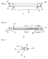
- FIGURE 2 is a top plan view of the housing of the connector;
- FIGURE 3 is a front elevational view of the housing of the connector;
- FIGURE 4 is a side elevational view of the housing of the connector;
- FIGURE 5 is a top plan view of the pressure member;
- FIGURE 6 is a front elevational view of the pressure member;
- FIGURE 7 is a side elevational view of the pressure member;
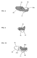
- FIGURE 8 is an enlarged vertical section taken generally along line H-H in Figure 6;
- FIGURE 9 is an enlarged vertical section taken generally along line K-K in Figure 6;
- FIGURE 10 is an enlarged vertical section taken generally along line J-J in Figure 6;
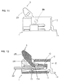
- FIGURE 11 is a side elevational view of another embodiment of a flat cable connector, with the pressure member in its open position; and
- FIGURE 12 is a front-to-rear vertical section through the flat cable connector of Figure 12.
- Referring to the drawings in greater detail, Figure 1 shows a first embodiment of a flexible flat cable connector according to the invention. The connector includes a housing 1 mounting a plurality of
terminals 2 in a generally parallel array. The housing rotatably mounts an actuator orcable pressure member 3. Details of the housing are shown in Figures 2-4, and details of the cable pressure member are shown in Figures 5-10. - Referring to Figures 2-4 in conjunction with Figure 1, housing 1 is unitarily molded of dielectric material such as plastic or the like. The housing includes a
base 5 having a plurality ofterminal slots 4 formed therein,opposite side walls 6 molded integrally to opposite lateral edges ofbase 5, and atop wall 7 extending transversely betweenopposite side walls 6. Each side wall has a cam slot ortrack 9 facing upwardly towardtop wall 7. As described in greater detail hereinafter,cable pressure member 3 has a counter cam on each opposite side thereof for cooperating withcam slot 9 for guiding the cable pressure member between its rotatable positions. - As seen in Figures 2 and 3,
top wall 7 extends short of the front end of housing 1, thereby leaving a space or opening 8 at the front of the housing. The opening coincides with a cable insertion opening, generally designated 21, into which a flexibleflat cable 22 can be inserted in the direction of arrow 23 (Fig. 3). Lastly, housing 1 includes stop means in the form of a pair of overhangingextensions 24 projecting inwardly fromopposite side walls 6 and overhanging the opposite edges 22a of flexibleflat cable 22 as best seen in Figure 3. - Each
terminal 2 is stamped from sheet metal material in a bifurcated shape as best seen in Figure 1. The bifurcated shape defines a relatively shortupper support leg 10 and a relatively longlower contact leg 11.Support leg 10 has abarb 12, and the terminal is fixed in a respective one of theterminal slots 4 bybarb 12 ofsupport leg 10 biting into an intermediate shelf 1a of the housing. Contactleg 11 has acontact portion 13 projecting from the free end of the leg upwardly towardsupport leg 10. An L-shaped soldering tail 14 extends rearwardly of the terminal and outwardly of housing 1. The bottom of the L-shaped soldering tail 14 is flush with the bottom surface ofbase 5 of the housing for soldering to a circuit trace on an appropriate printed circuit board. - Referring to Figures 5-10 in conjunction with Figures 1-4,
cable pressure member 3 is unitarily molded of dielectric material, such as plastic or the like. The pressure member includes a majorflat plate 15 which is wide enough to span the opening 8 at the front of housing 1.Triangular flanges 16 are molded integrally at opposite sides offlat plate 15. Eachtriangular flange 16 has acounter cam 17 at the front thereof. Eachtriangular flange 16 is positioned so that itscounter cam 17 confronts the cam slot or track 9 (Fig. 4) in a respective one of the side walls of the housing. - Major
flat plate 15 ofcable pressure member 3 has a width sized to fit in the space between theopposite overhanging extensions 24 of housing 1 as the cable pressure member moves from a first open position allowing insertion offlat cable 22 into opening 8 in the housing, and a second closed position pressing conductors of the flat cable againstcontact portions 13 ofterminals 2 as shown in Figure 1. As seen in Figures 8 and 10, majorflat plate 15 ofcable pressure member 3 has a steppedlower surface 25 at the front thereof. In addition, the cable pressure member has projections 18 (Figs. 5-7) projecting outwardly of its opposite sides. Eachprojection 18 fits into an L-shaped slot 19 (Fig. 2) in the inner surface of one of theside walls 6 of the housing. The cable pressure member also has roundedside projections 20 which form detents to snap over the inside edges of overhangingextensions 24 when the pressure member is moved between its open and closed positions. - Cam slots or
tracks 9 on housing 1 andcounter cams 17 oncable pressure member 3 cooperate functionally to guide the cable pressure between its rotatable positions. Specifically, when the cable pressure member is moved toward its closed position shown in Figure 1, arear end 15a (Fig. 8) of the cable pressure member moves under a comb-like support arrangement defined by the bottom surfaces 26 (Fig. 1) ofsupport legs 10 ofterminals 2. By this action,flat cable 22 is pinched between the undersurface of the cable pressure member andcontact portions 13 ofterminals 2. - Referring back to Figure 1 wherein flexible
flat cable 22 has been inserted into the connector, assume that the flat cable is pulled upwardly as shown in broken lines by undesired external forces applied to the cable. In a conventional electrical connector structure, the cable pressure member would be rotated toward its open position in the direction indicated byarrow 27. However, according to the concepts of the present invention in the electrical connector structure shown herein, theflat cable 22 will move or bend the cable pressure member upwardly only a small degree until the flat cable is stopped by the overhangingextensions 24 extending inwardly from the opposite sides of the housing. Further upward pulling on the cable is prevented and the cable pressure member will not move toward its open position. Therefore, undesired release or decoupling of the flat cable from the connector is stopped. It can be seen that a triangular space 28 (Fig. 1) is formed beneath overhangingextensions 24 which, in effect, defines the limit of movement of the flat cable in the event that undesired upward forces are applied thereto. - In the electrical connector described above in relation to the embodiment of Figures 1-10, housing 1 is provided with
cam slots 9 andcable pressure member 3 is provided withcounter cams 17 for assuring a smooth rotation and displacement of the cable pressure member toward its closed, cable pinching position. However, such cam means can be omitted as shown in the embodiment of Figures 11 and 12. In other words,pressure member 3 in Figures 11 and 12 is movable from its open position, as shown, about pivots 29 between opposite sides of the cable pressure member and the insides of the side walls of the housing, but no cam means are provided. - Lastly, it should be understood that the supporting
undersurfaces 26 of thesupport legs 10 ofterminals 2 can be readily replaced by a transversely extending portion of housing 1. Still further,soldering tails 14 ofterminals 2 may comprise pin-like projections for insertion into appropriate holes in a printed circuit board and for soldering to appropriate circuit traces on the board and/or in the holes. - It will be understood that the invention may be embodied in other specific forms without departing from the spirit or central characteristics thereof. The present examples and embodiments, therefore, are to be considered in all respects as illustrative and not restrictive, and the invention is not to be limited to the details given herein.
Claims (7)
- An electrical connector for a flat cable (22), comprising:a housing (1) mounting a plurality of terminals (2) in a generally parallel array, the housing having opposite sides (6) and a front end with an opening (8,21) between the sides for receiving an end of the flat cable (22) in engagement with contact portions (13) of the terminals;a pressure member (3) rotatably mounted on the housing (1) for movement between a first position allowing insertion of the flat cable (22) into the opening (8,21) and a second position pressing conductors of the flat cable against the contact portions (13) of the terminals (2); andstop means (24) on the housing (1) preventing release of the flat cable (22) from the electrical connector in the event undesired external forces are applied to the cable which would tend to bias the pressure member (3) toward its first position.
- The electrical connector of claim 1 wherein said stop means comprise overhanging extensions (24) projecting inwardly from the opposite sides (6) of the housing (1).
- The electrical connector of claim 1 wherein said stop means (24) are located on said opposite sides (6) of the housing (1).
- The electrical connector of claim 3 wherein said pressure member (3) includes an actuating portion (15) having a width sized to fit between the stop means (24) on the opposite sides of the housing.
- The electrical connector of claim 1, including pivot means (9,17,29) rotatably mounting the pressure member (3) on the housing (1), the pivot means being located rearwardly of said stop means (24).
- The electrical connector of claim 5 wherein said pivot means comprise a pair of pivots (9,17,29) between opposite sides of the pressure member (3) and said opposite sides (6) of the housing (1).
- The electrical connector of claim 1 wherein said pressure member (3) includes a stepped lower surface (25) at the front thereof defining a generally triangular space between the pressure member and the flat cable (22) when the pressure member is in its second position.
Applications Claiming Priority (2)
| Application Number | Priority Date | Filing Date | Title |
|---|---|---|---|
| JP1995006643U JP3019288U (en) | 1995-06-08 | 1995-06-08 | Electrical connector for flat flexible cable |
| JP6643/95U | 1995-06-08 |
Publications (2)
| Publication Number | Publication Date |
|---|---|
| EP0747996A2 true EP0747996A2 (en) | 1996-12-11 |
| EP0747996A3 EP0747996A3 (en) | 1997-10-01 |
Family
ID=11644057
Family Applications (1)
| Application Number | Title | Priority Date | Filing Date |
|---|---|---|---|
| EP96108130A Withdrawn EP0747996A3 (en) | 1995-06-08 | 1996-05-22 | Flat cable connector |
Country Status (5)
| Country | Link |
|---|---|
| US (1) | US5895287A (en) |
| EP (1) | EP0747996A3 (en) |
| JP (1) | JP3019288U (en) |
| SG (1) | SG72694A1 (en) |
| TW (1) | TW363794U (en) |
Cited By (5)
| Publication number | Priority date | Publication date | Assignee | Title |
|---|---|---|---|---|
| GB2330244A (en) * | 1997-07-30 | 1999-04-14 | Whitaker Corp | Flexible card connector |
| EP0895320A3 (en) * | 1997-07-29 | 2000-03-01 | Hirose Electric Co., Ltd. | Flexible board electrical connector |
| SG97172A1 (en) * | 1999-12-17 | 2003-07-18 | Connector Systems Tech Nv | Connector for a flat cable |
| CN112290251A (en) * | 2020-09-14 | 2021-01-29 | 泰州市航宇电器有限公司 | Miniaturized surface-mounted large-current connector |
| US11936129B2 (en) | 2021-01-14 | 2024-03-19 | Te Connectivity Germany Gmbh | Ribbon cable connector with a clamping device |
Families Citing this family (9)
| Publication number | Priority date | Publication date | Assignee | Title |
|---|---|---|---|---|
| JPH118025A (en) * | 1997-06-16 | 1999-01-12 | Amp Japan Ltd | Circuit device |
| US6210210B1 (en) | 2000-02-17 | 2001-04-03 | Methode Electronics, Inc. | Flat conductor termination device |
| JP3446136B2 (en) | 2000-06-05 | 2003-09-16 | モレックス インコーポレーテッド | Electrical connector |
| TW582631U (en) * | 2003-06-27 | 2004-04-01 | Hon Hai Prec Ind Co Ltd | Electrical connector |
| TWM250340U (en) * | 2003-08-01 | 2004-11-11 | Hon Hai Prec Ind Co Ltd | Electrical connector |
| CN2718819Y (en) * | 2004-06-23 | 2005-08-17 | 富士康(昆山)电脑接插件有限公司 | Flexible printed circuit connector |
| US20070054558A1 (en) * | 2005-09-03 | 2007-03-08 | Harlan Tod M | Connector with improved pulling portion |
| US7727006B1 (en) * | 2009-07-23 | 2010-06-01 | Cheng Uei Precision Industry Co., Ltd. | Connector for flexible printed circuit board |
| CN104904070B (en) * | 2012-12-11 | 2018-11-13 | 诺基亚技术有限公司 | The device and method that socket contact for contacting flexible flat connector is provided |
Family Cites Families (15)
| Publication number | Priority date | Publication date | Assignee | Title |
|---|---|---|---|---|
| US4477137A (en) * | 1982-08-23 | 1984-10-16 | Allied Corporation | Zero insertion force connector for flat cable |
| US4630874A (en) * | 1985-06-20 | 1986-12-23 | Amp Incorporated | Zero insertion force electrical interconnection assembly |
| US4639063A (en) * | 1985-12-20 | 1987-01-27 | Amp Incorporated | Electrical connector for flexible film circuits |
| JPS63274074A (en) * | 1987-05-01 | 1988-11-11 | アンプ インコ−ポレ−テツド | Printed board connector |
| JPH088550Y2 (en) * | 1988-01-14 | 1996-03-06 | アンプ インコーポレーテッド | Flat cable connector |
| DE3822980A1 (en) * | 1988-07-07 | 1990-01-11 | Lumberg Karl Gmbh & Co | Connector for the connection of flat electrical conductors |
| JPH0286080A (en) * | 1988-09-21 | 1990-03-27 | Nippon Burndy Kk | Connector for flat cable |
| JP2764647B2 (en) * | 1990-06-29 | 1998-06-11 | 蛇の目ミシン工業株式会社 | Embroidery sewing machine |
| JPH0724230B2 (en) * | 1990-10-25 | 1995-03-15 | 京セラエルコ株式会社 | No insertion / removal force connector |
| JPH069152B2 (en) * | 1991-06-18 | 1994-02-02 | モレックス インコーポレーテッド | Card edge connector for horizontal board connection and its manufacturing method |
| DE4141376C2 (en) * | 1991-12-14 | 1993-12-02 | Hirschmann Richard Gmbh Co | Foil connectors |
| TW233382B (en) * | 1993-04-02 | 1994-11-01 | Hirose Electric Co Ltd | |
| JP2820855B2 (en) * | 1993-04-07 | 1998-11-05 | トーマス アンド ベッツ コーポレーション | connector |
| JPH0722129A (en) * | 1993-07-05 | 1995-01-24 | Kiyousera Elco Kk | Lcd connector device |
| JP2892945B2 (en) * | 1994-08-05 | 1999-05-17 | ヒロセ電機株式会社 | Electrical connector for flexible board |
-
1995
- 1995-06-08 JP JP1995006643U patent/JP3019288U/en not_active Expired - Lifetime
-
1996
- 1996-04-23 TW TW086210898U patent/TW363794U/en unknown
- 1996-05-14 US US08/647,501 patent/US5895287A/en not_active Expired - Fee Related
- 1996-05-22 EP EP96108130A patent/EP0747996A3/en not_active Withdrawn
- 1996-06-07 SG SG1996010012A patent/SG72694A1/en unknown
Cited By (5)
| Publication number | Priority date | Publication date | Assignee | Title |
|---|---|---|---|---|
| EP0895320A3 (en) * | 1997-07-29 | 2000-03-01 | Hirose Electric Co., Ltd. | Flexible board electrical connector |
| GB2330244A (en) * | 1997-07-30 | 1999-04-14 | Whitaker Corp | Flexible card connector |
| SG97172A1 (en) * | 1999-12-17 | 2003-07-18 | Connector Systems Tech Nv | Connector for a flat cable |
| CN112290251A (en) * | 2020-09-14 | 2021-01-29 | 泰州市航宇电器有限公司 | Miniaturized surface-mounted large-current connector |
| US11936129B2 (en) | 2021-01-14 | 2024-03-19 | Te Connectivity Germany Gmbh | Ribbon cable connector with a clamping device |
Also Published As
| Publication number | Publication date |
|---|---|
| JP3019288U (en) | 1995-12-12 |
| EP0747996A3 (en) | 1997-10-01 |
| SG72694A1 (en) | 2000-05-23 |
| TW363794U (en) | 1999-07-01 |
| US5895287A (en) | 1999-04-20 |
Similar Documents
| Publication | Publication Date | Title |
|---|---|---|
| US5695360A (en) | Zero insertion force electrical connector for flat cable | |
| US6551128B2 (en) | Connector for connecting flexible substrates | |
| US6726497B2 (en) | Connector for flat flexible cable | |
| EP0947944B1 (en) | Card reader connector | |
| US5240430A (en) | Electrical connector for cable to circit board application | |
| US5895287A (en) | Flat cable connector | |
| KR950003111Y1 (en) | Electrical Connectors for Flat Electrical Cables | |
| JP2835563B2 (en) | Edge connectors for printed circuit boards | |
| CN101536267B (en) | Relay Connectors for Flexible Cables | |
| US4341429A (en) | Electrical connector | |
| US6056571A (en) | Electrical connector for flat electrical conductor | |
| US6837740B2 (en) | Flat circuit connector | |
| KR20030040125A (en) | Connector for flat flexible cable | |
| KR20040042773A (en) | Electric connector for flat type conductor connection | |
| US5934932A (en) | Electrical connector for flat cables | |
| US5921785A (en) | Electrical connector for flat cables | |
| US4332431A (en) | Preassembled electrical connector | |
| US5692920A (en) | Zero insertion force electrical connector and terminal | |
| US5791929A (en) | Zero insertion force electrical connector and terminal | |
| US5597320A (en) | Zero insertion force electrical connector and terminal | |
| US7344399B2 (en) | Flat circuit connector | |
| US5863217A (en) | Lock mechanism for FPC connector | |
| US7029319B2 (en) | Flat circuit connector | |
| US5451172A (en) | Connector for flat cables | |
| US5741154A (en) | Electrical connector for flat cable |
Legal Events
| Date | Code | Title | Description |
|---|---|---|---|
| PUAI | Public reference made under article 153(3) epc to a published international application that has entered the european phase |
Free format text: ORIGINAL CODE: 0009012 |
|
| AK | Designated contracting states |
Kind code of ref document: A2 Designated state(s): DE FR GB IT |
|
| PUAL | Search report despatched |
Free format text: ORIGINAL CODE: 0009013 |
|
| RHK1 | Main classification (correction) |
Ipc: H01R 23/68 |
|
| AK | Designated contracting states |
Kind code of ref document: A3 Designated state(s): DE FR GB IT |
|
| 17P | Request for examination filed |
Effective date: 19980224 |
|
| 17Q | First examination report despatched |
Effective date: 20000128 |
|
| RIC1 | Information provided on ipc code assigned before grant |
Free format text: 7H 01R 12/16 A, 7H 01R 12/24 B |
|
| GRAG | Despatch of communication of intention to grant |
Free format text: ORIGINAL CODE: EPIDOS AGRA |
|
| GRAG | Despatch of communication of intention to grant |
Free format text: ORIGINAL CODE: EPIDOS AGRA |
|
| GRAH | Despatch of communication of intention to grant a patent |
Free format text: ORIGINAL CODE: EPIDOS IGRA |
|
| GRAH | Despatch of communication of intention to grant a patent |
Free format text: ORIGINAL CODE: EPIDOS IGRA |
|
| STAA | Information on the status of an ep patent application or granted ep patent |
Free format text: STATUS: THE APPLICATION IS DEEMED TO BE WITHDRAWN |
|
| 18D | Application deemed to be withdrawn |
Effective date: 20021203 |