EP0748752B1 - Vorrichtung zum Überführen von Gegenständen - Google Patents
Vorrichtung zum Überführen von Gegenständen Download PDFInfo
- Publication number
- EP0748752B1 EP0748752B1 EP96109509A EP96109509A EP0748752B1 EP 0748752 B1 EP0748752 B1 EP 0748752B1 EP 96109509 A EP96109509 A EP 96109509A EP 96109509 A EP96109509 A EP 96109509A EP 0748752 B1 EP0748752 B1 EP 0748752B1
- Authority
- EP
- European Patent Office
- Prior art keywords
- cradle
- unit
- conveying device
- transfer
- Prior art date
- Legal status (The legal status is an assumption and is not a legal conclusion. Google has not performed a legal analysis and makes no representation as to the accuracy of the status listed.)
- Expired - Lifetime
Links
Images

Classifications
-
- B—PERFORMING OPERATIONS; TRANSPORTING
- B65—CONVEYING; PACKING; STORING; HANDLING THIN OR FILAMENTARY MATERIAL
- B65G—TRANSPORT OR STORAGE DEVICES, e.g. CONVEYORS FOR LOADING OR TIPPING, SHOP CONVEYOR SYSTEMS OR PNEUMATIC TUBE CONVEYORS
- B65G47/00—Article or material-handling devices associated with conveyors; Methods employing such devices
- B65G47/74—Feeding, transfer, or discharging devices of particular kinds or types
- B65G47/82—Rotary or reciprocating members for direct action on articles or materials, e.g. pushers, rakes, shovels
Definitions
- the present invention relates to a product transfer unit, according to the preamble of claim 1.
- the two lines are defined by conveying devices presenting a number of pockets, each connected rigidly to the movable element of the respective conveying device, and each designed to house a product of a given shape and size. Normally, the pockets are equally spaced along the transportation branches of the conveying devices.
- the transfer unit presents a single transfer member moving reciprocatingly in a direction perpendicular to the traveling direction of the conveying devices to connect two pockets arrested at the transfer station.
- the input conveying device must also be operated likewise. More specifically, the two conveying devices must be so timed that the respective pockets travel in pairs to define a conveying channel for the products. Understandably, the transfer device must therefore provide for transferring the products with the pockets of the two conveyors in motion, and must therefore comprise a number of transfer members, the motion of which is a combination of the continuous motion of the product in the traveling direction of the conveying devices, and the reciprocating motion of the transfer member for transferring the product crosswise to the traveling direction of the conveying devices. This therefore results in a highly complex transfer device in turn resulting in complex setup and maintenance of the cartoning machine.
- EP-A-0 030 359 discloses a transfer unit for products comprising a transfer station, and at least a conveying device moving continuously through the transfer station, and provided with a number of pockets equally spaced along the conveying device itself. Each pocket is movable guided and is actuated in such a way that, in the transfer station, the pocket stops temporarily so as to allow the transfer of a product into the pocket.
- the actuating device which moves the pockets is complicated (i.e. expansive), and does not allow working at relatively high speed.
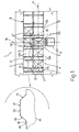
- Number 1 in Figure 1 indicates a transfer unit for transferring products 2, and comprising a transfer station 3; an input conveyor 4 operating in steps; and an output conveyor 5 operating continuously; both conveyors 4 and 5 being endless conveyors, extending in a traveling direction 6 of products 2, and presenting respective upper transportation branches 7 and 8, and respective numbers of pockets 10a and 10b equally spaced with a first and second given spacing.
- Branches 7 and 8 are located side by side at station 3, at which unit 1 comprises a transfer assembly 11 for transferring products 2 between pockets 10a and 10b of conveyors 4 and 5, as described in detail later on.
- conveyor 5 comprises a transportation member 12 comprising a number of cylindrical pins 13 equally spaced along branch 8 with their longitudinal axes perpendicular to direction 6, so as to define a horizontal surface along branch 8.
- Each pin 13 is fitted in angularly fixed manner with a parallelepiped support 14 located beneath and supporting pocket 10b as described in detail later on.
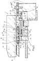
- Each pocket 10b presents a cradle 15, which is open in a direction 16 perpendicular to direction 6 and presents two substantially vertical side walls 17 extending upwards from a substantially horizontal bottom wall 18.
- Each pocket 10b presents a parallelepiped projection 19 projecting downwards from wall 18 at the side wall 17 on the side of pocket 10b preceding cradle 15 in the traveling direction of conveyors 4 and 5.
- Projection 19 presents a pair of holes 20 parallel to direction 6, and each housing an end portion of a respective cylindrical pin 21 smaller in diameter than the height of projection 19 and parallel to direction 6.
- Pins 21 are maintained parallel to each other by a connecting member 22, which is similar to projection 19 and is engaged integrally, at respective holes 23, by the free ends of pins 21.
- Each pocket 10b also presents a substantially horizontal plate 24, which is located beneath wall 18, is fitted integral with projection 19, and presents an arm 25 extending on the opposite side of conveyor 5 to conveyor 4.
- Wall 18 and plate 24 respectively define the top and bottom of a chamber, which, measured vertically, presents approximately the same height as projection 19 and houses pins 21.
- Pocket 10b presents a body 26 partially engaging said chamber, and presenting two holes 27 parallel to direction 6 and the center distance of which substantially equals that of pins 21. Together, pins 21 and body 26 with holes 27 define a guide device 21a for guiding the movement of cradle 15 in direction 6.
- Body 26 is fitted rigidly to support 14, supports pocket 10b by means of pins 21 to which body 26 is connected in freely sliding manner, and presents, on the connecting member 22 side, a cavity 28 defined by two lateral walls 29 substantially parallel to pins 21, and by an end wall 30 perpendicular to pins 21.
- Body 26 also presents two substantially cylindrical appendixes 31 projecting outwards with their respective axes substantially coplanar with the axes of pins 21; and projection 19 presents two appendixes 32 substantially identical to appendixes 31.
- the function of appendixes 31 and 32 will be explained in detail later on.
- pocket 10b comprises an articulated device 33 for varying the position of projection 19 in relation to body 26.
- device 33 comprises a rocker arm 34 presenting an arm 35 substantially parallel to direction 6 and extending in the traveling direction of products 2, and an arm 36 perpendicular to arm 35 and facing body 26.
- rocker arm 34 is hinged by a vertical pin 37 to one end of arm 25; the free end 38 of arm 35 is fitted with a tappet roller 39 via the interposition of a vertical pin 40; and the free end 41 of arm 36 is hinged by a pin 42 to a lever 43 connecting rocker arm 34 to wall 18 of cradle 15 via the interposition of a pin 44.
- device 33 On the opposite side of conveyor 5 to conveyor 4, device 33 also comprises a horizontal cam 45 fitted by screws 45a to a frame 1a of unit 1, and which is located on a level with roller 39 with which it cooperates by means of an edge 46 presenting a step portion 47 extending towards conveyor 5 from a portion 48 parallel to direction 6 and for releasing roller 39. More specifically, at transfer station 3, portion 47 presents, in succession in the traveling direction of transportation member 12, an inclined leading portion 49 for rotating rocker arm 34 anticlockwise and so slowing down cradle 15 in relation to transportation member 12; an idle portion 50 parallel to portion 48; and a further inclined portion 51 for accelerating cradle 15 and so restoring it to a distance equal to the spacing of the preceding and following cradles 15.
- portion 49 determines the manner in which pockets 10b are slowed down, which, in this case, also includes the stoppage of each pocket 10b facing transfer assembly 11 at station 3.
- Device 33 also comprises a pair of springs 53 (only one shown in Figure 3), each extending between two facing appendixes 31 and 32, so that, when roller 39 engages portion 48, pocket 10b is maintained in the idle position with body 26 and projection 19 pushed against each other and cradle 15 equidistant in relation to the preceding and following pockets 10b; whereas, when roller 39 engages portion 47, springs 53 provide for maintaining rolling contact between roller 39 and portion 47.
- conveyor 4 differs from conveyor 5 as to the manner in which pockets 10a are advanced, and by pockets 10a being defined by cradles 55 substantially identical to cradles 15 but connected rigidly in known manner (not shown) to pins of conveyor 4 substantially equivalent to pins 13.
- conveyor 4 is so operated as to successively arrest pockets 10a at station 3.
- Transfer assembly 11 presents a single pusher 54 moving reciprocatingly, parallel to direction 16 and in time with conveyor 4, along a channel 52 defined by two pockets 10a, 10b arrested at transfer station 3.
- portion 47 arrests each pocket 10b facing pusher 54 long enough to enable pusher 54 to move along channel 52 and transfer product 2 from pocket 10a to pocket 10b.
- conveyor 4 supplies products 2 to station 3 in respective pockets 10a.
- roller 39 of device 33 engages portion 49 to slow down the corresponding cradle 15 (dotted line in Figure 3) and eventually arrest it facing pusher 54.
- conveyor 4 arrests a respective pocket 10a in station 3, and pusher 54 is moved by transfer assembly 11 along channel 52 defined by the two pockets 10a and 10b to transfer product 2 from conveyor 4 to conveyor 5.
- unit 1 may be so formed as to comprise a conveyor 4 substantially identical to conveyor 5, in which case, conveyor 4 must be modified and respective pockets 10a replaced by others identical to pockets 10b.
Landscapes
- Engineering & Computer Science (AREA)
- Mechanical Engineering (AREA)
- Intermediate Stations On Conveyors (AREA)
- Branching, Merging, And Special Transfer Between Conveyors (AREA)
- Special Conveying (AREA)
Claims (6)
- Übergabeeinheit (1) für Waren, wobei die Einheit eine Übergabestation (3); mindestens eine erste Fördereinrichtung (5) mit einem Transportglied (12), welches einen Transportbereich (8) verkörpert und sich kontinuierlich in einer ersten Bewegungsrichtung durch die Übergabestation (3) bewegt; und eine Übergabebaugruppe (11) mit einem Schieber (54) aufweist, welcher für die Übergabe der Waren an die erste Fördereinrichtung (5) in einer rechtwinklig zur ersten Richtung (6) verlaufenden zweiten Richtung (16) durch die Übergabestation (3) hin und her bewegbar ist; wobei die erste Fördereinrichtung (5) mehrere erste Behälter (10b) hat, welche entlang des ersten Transportbereiches (8) jeweils gleichmäßig zueinander in einem ersten Abstand beabstandet sind; und wobei jeder erste Behälter ein erstes Gestell (15) verkörpert, welches parallel zur zweiten Richtung (16) offen ist und einen im Wesentlichen horizontalen Boden (18) bietet;
dadurch gekennzeichnet,dass jeder erste Behälter (10b) ein Führungsmittel (21a) zum Führen des ersten Gestells (15) in dessen Bewegung aufweist, welches sich in die zweite Richtung (16) erstreckt;dass das Führungsmittel (21a) einen einstückig mit dem Transportglied (12) ausgebildeten ersten Abschnitt und einen einstückig mit dem Gestell (15) ausgebildeten zweiten Abschnitt aufweist, welcher bezüglich des ersten Abschnitts verschieblich ist; unddass ein erstes Betätigungsmittel (33) an der Übergabestation (3) vorgesehen ist, um das erste Gestell (15) bezüglich des entsprechenden Transportgliedes (12) in erster Richtung (6) in eine und aus einer Ruhestellung derart hin und her zu bewegen, dass das erste Gestell (15) zeitweise an der Übergabestation (3) still steht;wobei das erste Betätigungsmittel (33) eine feststehende Kurve (45) und eine angelenkte Vorrichtung (33) aufweist, welche einen schwenkbar am ersten Abschnitt des Führungsmittels (21a) vorgesehenen Mitnehmerarm (34) aufweist, der ein mit der Kurve (45) zusammenwirkendes erstes Ende (38) und ein mit dem zweiten Abschnitt des Führungsmittels (21a) verbundenes zweites Ende (41) aufweist. - Einheit nach Anspruch 1, wobei die drehbare Vorrichtung (33) ferner einen Hebel (43) aufweist, der das zweite Ende (41) des Mitnehmerarms (34) mit dem zweiten Abschnitt des Führungsmittels (21) verbindet.
- Einheit nach Anspruch 1 oder 2, wobei die Kurve (45) einen wirksamen Abschnitt (47) verkörpert, der einen parallel zur ersten Richtung (6) verlaufenden Ruheabschnitt (50) sowie eine erste und zweite Rampe (49, 51) aufweist, welche den Ruheabschnitt (50) definieren; die erste Rampe (49) den Mitnehmerarm (34) derart schwenkt, um das erste Gestell (15) bezüglich des Transportgliedes (12) rückwärts zu fahren, den Abstand zwischen dem ersten Gestell (15) und dem dem ersten Gestell (15) vorgeordneten ersten Behälter (10b) zu vergrößern und den Abstand zwischen dem ersten Gestell (15) und dem dem ersten Gestell (15) nachfolgenden ersten Behälter (10d) zu verkleinern; und die zweite Rampe (51) das erste Gestell (15) bezüglich des Transportgliedes (12) derart vorwärts bewegt, dass die Abstände zwischen dem ersten Gestell (15) und den beiden zum ersten Gestell (15) unmittelbar benachbarten ersten Behältern (10b) jeweils dem ersten Abstand entsprechen.
- Einheit nach einem der vorhergehenden Ansprüche, wobei die Kurve (45) und die angelenkte Vorrichtung (33) unterhalb des ersten Gestells (15) angeordnet sind.
- Einheit nach einem der vorhergehenden Ansprüche, die mindestens eine zweite Fördereinrichtung (4) aufweist, welche entlang der ersten Fördereinrichtung (5) angeordnet ist, wobei die zweite Fördereinrichtung (4) mehrere zweite Gestelle (55) aufweist, welche mit einem zweiten Abstand gleichmäßig zueinander beabstandet sind; und wobei jedes zweite Gestell (55) im Wesentlichen zu einem ersten Gestell (15) identisch ist.
- Einheit nach Anspruch 5, wobei die zweite Fördereinrichtung (4) schrittweise getaktet mit der Übergabebaugruppe (11) derart arbeitet, dass das erste und zweite Gestell (15, 55) an der Übergabestation (3) einen Kanal (52) definieren, der in die zweite Richtung (16) verläuft, damit ein Produkt zwischen der ersten und der zweiten Fördereinrichtung (5, 4) ausgetauscht werden kann.
Applications Claiming Priority (2)
| Application Number | Priority Date | Filing Date | Title |
|---|---|---|---|
| ITBO950304 | 1995-06-15 | ||
| IT95BO000304A IT1279951B1 (it) | 1995-06-15 | 1995-06-15 | Unita' di trasferimento di prodotti |
Publications (2)
| Publication Number | Publication Date |
|---|---|
| EP0748752A1 EP0748752A1 (de) | 1996-12-18 |
| EP0748752B1 true EP0748752B1 (de) | 2001-12-05 |
Family
ID=11340676
Family Applications (1)
| Application Number | Title | Priority Date | Filing Date |
|---|---|---|---|
| EP96109509A Expired - Lifetime EP0748752B1 (de) | 1995-06-15 | 1996-06-13 | Vorrichtung zum Überführen von Gegenständen |
Country Status (6)
| Country | Link |
|---|---|
| US (1) | US5893447A (de) |
| EP (1) | EP0748752B1 (de) |
| JP (1) | JP3822674B2 (de) |
| DE (1) | DE69617534T2 (de) |
| ES (1) | ES2167490T3 (de) |
| IT (1) | IT1279951B1 (de) |
Families Citing this family (10)
| Publication number | Priority date | Publication date | Assignee | Title |
|---|---|---|---|---|
| CN1093832C (zh) * | 1996-12-13 | 2002-11-06 | 费拉格有限公司 | 用于输送各自被夹持的产品的方法和设备 |
| CA2256968C (en) * | 1997-12-24 | 2006-10-24 | Lawson Automotive Inc. | Pallet retention and release system |
| US6213285B1 (en) * | 1998-11-25 | 2001-04-10 | International Business Machines Corporation | Method of indexing conveyor pallets at high speeds |
| FR2788043B1 (fr) * | 1998-12-30 | 2001-02-16 | Gallet Systemes Automatises | Convoyeur a chaine, tel que carrousel pour machine d'installation logistique, et machine telle que pour le tri d'objets plats |
| US6454076B1 (en) * | 2001-01-05 | 2002-09-24 | Gebo Corporation Usa | Scissors chute |
| US6516937B1 (en) | 2002-05-17 | 2003-02-11 | Lockheed Martin Corporation | Under roller conveyor pusher assembly |
| JP3849865B2 (ja) * | 2002-06-27 | 2006-11-22 | 株式会社椿本チエイン | 郵便物仕分配送用移載装置 |
| US6868959B2 (en) * | 2002-12-23 | 2005-03-22 | Timothy N. Thomas | Cam for accumulating conveyor |
| ITTO20040570A1 (it) * | 2004-08-18 | 2004-11-18 | Bottero Spa | Gruppo di movimentazione per il trasferimento di articoli di vetro |
| ITBO20050058A1 (it) * | 2005-02-07 | 2006-08-08 | Oam Spa | Linea per il convogliamento di articoli |
Citations (1)
| Publication number | Priority date | Publication date | Assignee | Title |
|---|---|---|---|---|
| EP0030359A1 (de) * | 1979-12-07 | 1981-06-17 | FOCKE & CO. | Vorrichtung zum Verpacken von Zigaretten od. dgl. |
Family Cites Families (6)
| Publication number | Priority date | Publication date | Assignee | Title |
|---|---|---|---|---|
| US2514104A (en) * | 1946-11-06 | 1950-07-04 | Budd Co | Conveyer mechanism |
| IT982256B (it) * | 1973-03-09 | 1974-10-21 | Mantovani Dante | Dispositivo per l accumulo e il trasferimento di prodotti da una linea erogatrice ad una linea ri cevitrice procedenti con velocita diverse |
| US3934701A (en) * | 1975-03-28 | 1976-01-27 | Mooney Engineering, Inc. | Linear indexing machine |
| EP0421492B1 (de) * | 1985-07-11 | 1994-07-20 | AXIS S.p.A. | Produktionslinie für auf Palette montierte Ständer elektrischer Motoren und Verfahren zur Herstellung solcher Ständer. |
| NL9101821A (nl) * | 1991-10-30 | 1993-05-17 | Tas Adrianus Wilhelmus | Werkwijze en inrichting voor het op gewicht sorteren van in hoofdzaak ronde produkten. |
| IT1274073B (it) * | 1994-10-19 | 1997-07-15 | Ima Spa | Dispositivo perfezionato per l'alimetazione di articoli a una linea di confezionamento in relativi contenitori |
-
1995
- 1995-06-15 IT IT95BO000304A patent/IT1279951B1/it active IP Right Grant
-
1996
- 1996-06-12 US US08/662,131 patent/US5893447A/en not_active Expired - Lifetime
- 1996-06-13 EP EP96109509A patent/EP0748752B1/de not_active Expired - Lifetime
- 1996-06-13 ES ES96109509T patent/ES2167490T3/es not_active Expired - Lifetime
- 1996-06-13 DE DE69617534T patent/DE69617534T2/de not_active Expired - Lifetime
- 1996-06-17 JP JP15586196A patent/JP3822674B2/ja not_active Expired - Lifetime
Patent Citations (1)
| Publication number | Priority date | Publication date | Assignee | Title |
|---|---|---|---|---|
| EP0030359A1 (de) * | 1979-12-07 | 1981-06-17 | FOCKE & CO. | Vorrichtung zum Verpacken von Zigaretten od. dgl. |
Also Published As
| Publication number | Publication date |
|---|---|
| EP0748752A1 (de) | 1996-12-18 |
| DE69617534D1 (de) | 2002-01-17 |
| IT1279951B1 (it) | 1997-12-23 |
| JPH0912141A (ja) | 1997-01-14 |
| ES2167490T3 (es) | 2002-05-16 |
| DE69617534T2 (de) | 2002-08-01 |
| US5893447A (en) | 1999-04-13 |
| JP3822674B2 (ja) | 2006-09-20 |
| ITBO950304A1 (it) | 1996-12-15 |
Similar Documents
| Publication | Publication Date | Title |
|---|---|---|
| US5155968A (en) | Continuous to intermittent feeding interface | |
| JP3868490B2 (ja) | 多数個パックの包装装置 | |
| US5310041A (en) | Device for equally-spaced transportation of randomly arranged incoming products | |
| US5893447A (en) | Product transfer unit | |
| EP0139775B1 (de) | Stau- und Transportvorrichtung für Gegenstände | |
| CA2330353A1 (fr) | Dispositif pour la constitution de lots successifs d'articles comprenant des moyens de transfert des articles | |
| EP1719706B1 (de) | Mehrzweckkartoniermaschine | |
| FI83752C (fi) | Inslagande foerpackningsmaskin. | |
| US6209706B1 (en) | Article grouping and transferring system | |
| US5735380A (en) | Suspended storage apparatus | |
| AU2000279724A1 (en) | Aseptic filling device | |
| EP0711719A1 (de) | Verfahren zum abstandsgleichen Fördern von Produkten und Förderband dazu | |
| US6168149B1 (en) | Method and unit for feeding blanks to a user machine | |
| JPH01167115A (ja) | 物品をワーキング・ステーションへ搬送する装置 | |
| US3374600A (en) | Method and apparatus for packaging | |
| US5230201A (en) | Block filling apparatus | |
| EP1232969B1 (de) | Vorrichtung zum Anordnen von Behältern, insbesondere von Flaschen, in gleichen Abständen | |
| US3887177A (en) | Sheet feeding mechanism | |
| JPS573721A (en) | Transfer device for glass forming machine | |
| US6349815B1 (en) | In-line stacker machine for stacking cookies | |
| CN216035341U (zh) | 一种用于饮料包装的分瓶机构 | |
| US5131523A (en) | Slide transfer | |
| US3634996A (en) | Bottle-packaging machine | |
| US2144761A (en) | Machine for feeding receptacles | |
| EP1433727B2 (de) | Vorrichtung zum Entleeren von Behältern von Obst und Gemüse |
Legal Events
| Date | Code | Title | Description |
|---|---|---|---|
| PUAI | Public reference made under article 153(3) epc to a published international application that has entered the european phase |
Free format text: ORIGINAL CODE: 0009012 |
|
| AK | Designated contracting states |
Kind code of ref document: A1 Designated state(s): DE ES FR GB |
|
| 17P | Request for examination filed |
Effective date: 19970520 |
|
| 17Q | First examination report despatched |
Effective date: 19990309 |
|
| GRAG | Despatch of communication of intention to grant |
Free format text: ORIGINAL CODE: EPIDOS AGRA |
|
| GRAG | Despatch of communication of intention to grant |
Free format text: ORIGINAL CODE: EPIDOS AGRA |
|
| GRAH | Despatch of communication of intention to grant a patent |
Free format text: ORIGINAL CODE: EPIDOS IGRA |
|
| GRAH | Despatch of communication of intention to grant a patent |
Free format text: ORIGINAL CODE: EPIDOS IGRA |
|
| GRAA | (expected) grant |
Free format text: ORIGINAL CODE: 0009210 |
|
| AK | Designated contracting states |
Kind code of ref document: B1 Designated state(s): DE ES FR GB |
|
| REG | Reference to a national code |
Ref country code: GB Ref legal event code: IF02 |
|
| REF | Corresponds to: |
Ref document number: 69617534 Country of ref document: DE Date of ref document: 20020117 |
|
| ET | Fr: translation filed | ||
| REG | Reference to a national code |
Ref country code: ES Ref legal event code: FG2A Ref document number: 2167490 Country of ref document: ES Kind code of ref document: T3 |
|
| PLBE | No opposition filed within time limit |
Free format text: ORIGINAL CODE: 0009261 |
|
| STAA | Information on the status of an ep patent application or granted ep patent |
Free format text: STATUS: NO OPPOSITION FILED WITHIN TIME LIMIT |
|
| 26N | No opposition filed | ||
| REG | Reference to a national code |
Ref country code: FR Ref legal event code: PLFP Year of fee payment: 20 |
|
| PGFP | Annual fee paid to national office [announced via postgrant information from national office to epo] |
Ref country code: ES Payment date: 20150527 Year of fee payment: 20 Ref country code: DE Payment date: 20150609 Year of fee payment: 20 Ref country code: GB Payment date: 20150610 Year of fee payment: 20 |
|
| PGFP | Annual fee paid to national office [announced via postgrant information from national office to epo] |
Ref country code: FR Payment date: 20150608 Year of fee payment: 20 |
|
| REG | Reference to a national code |
Ref country code: DE Ref legal event code: R071 Ref document number: 69617534 Country of ref document: DE |
|
| REG | Reference to a national code |
Ref country code: GB Ref legal event code: PE20 Expiry date: 20160612 |
|
| PG25 | Lapsed in a contracting state [announced via postgrant information from national office to epo] |
Ref country code: GB Free format text: LAPSE BECAUSE OF EXPIRATION OF PROTECTION Effective date: 20160612 |
|
| REG | Reference to a national code |
Ref country code: ES Ref legal event code: FD2A Effective date: 20160926 |
|
| PG25 | Lapsed in a contracting state [announced via postgrant information from national office to epo] |
Ref country code: ES Free format text: LAPSE BECAUSE OF EXPIRATION OF PROTECTION Effective date: 20160614 |