EP0748904A1 - Module pour système de construction à cellules préfabriquées - Google Patents
Module pour système de construction à cellules préfabriquées Download PDFInfo
- Publication number
- EP0748904A1 EP0748904A1 EP96109695A EP96109695A EP0748904A1 EP 0748904 A1 EP0748904 A1 EP 0748904A1 EP 96109695 A EP96109695 A EP 96109695A EP 96109695 A EP96109695 A EP 96109695A EP 0748904 A1 EP0748904 A1 EP 0748904A1
- Authority
- EP
- European Patent Office
- Prior art keywords
- solid wood
- module according
- module
- layers
- wood panel
- Prior art date
- Legal status (The legal status is an assumption and is not a legal conclusion. Google has not performed a legal analysis and makes no representation as to the accuracy of the status listed.)
- Withdrawn
Links
- 238000010276 construction Methods 0.000 title claims description 14
- 239000007787 solid Substances 0.000 claims abstract description 64
- 239000010410 layer Substances 0.000 claims abstract description 49
- 239000002356 single layer Substances 0.000 claims abstract description 6
- 239000002023 wood Substances 0.000 claims description 69
- 230000005540 biological transmission Effects 0.000 claims description 2
- 239000000463 material Substances 0.000 description 7
- 238000009434 installation Methods 0.000 description 4
- 238000004519 manufacturing process Methods 0.000 description 4
- 238000009413 insulation Methods 0.000 description 3
- 239000011120 plywood Substances 0.000 description 3
- 229910000831 Steel Inorganic materials 0.000 description 2
- 238000004026 adhesive bonding Methods 0.000 description 2
- 230000000694 effects Effects 0.000 description 2
- 239000010959 steel Substances 0.000 description 2
- 239000004566 building material Substances 0.000 description 1
- 229910052500 inorganic mineral Inorganic materials 0.000 description 1
- 230000001788 irregular Effects 0.000 description 1
- 239000011707 mineral Substances 0.000 description 1
- 238000005192 partition Methods 0.000 description 1
- 238000004904 shortening Methods 0.000 description 1
- 239000000725 suspension Substances 0.000 description 1
- 239000002699 waste material Substances 0.000 description 1
Images

Classifications
-
- E—FIXED CONSTRUCTIONS
- E04—BUILDING
- E04B—GENERAL BUILDING CONSTRUCTIONS; WALLS, e.g. PARTITIONS; ROOFS; FLOORS; CEILINGS; INSULATION OR OTHER PROTECTION OF BUILDINGS
- E04B1/00—Constructions in general; Structures which are not restricted either to walls, e.g. partitions, or floors or ceilings or roofs
- E04B1/348—Structures composed of units comprising at least considerable parts of two sides of a room, e.g. box-like or cell-like units closed or in skeleton form
- E04B1/34815—Elements not integrated in a skeleton
- E04B1/34838—Elements not integrated in a skeleton the supporting structure consisting of wood
Definitions
- the invention relates to a module for a room cell construction.
- the present invention has for its object to provide a simple and effective module for a room cell construction, which has the smallest possible height, leads to the lowest possible overall height of the structure when using one or more modules to create a building and that particularly light and is to be transported efficiently.
- the module should also be particularly cost-effective and, in at least one embodiment, can be produced without impairing its function using relatively low-quality building material.
- a module according to the invention for a room cell construction, with floor, wall and ceiling elements which form an essentially cuboid module structure, at least the floor element consisting of a multi-layer solid wood panel.
- the floor element consisting of a multi-layer solid wood panel.
- one or more floor, wall or ceiling elements to consist of the solid wood panel according to the invention.
- the solid wood panel is therefore not plywood or plywood, such as plywood, which is a panel made from several layers of wood glued together, in particular peeling veneers.
- the module according to the invention has a very low overall height for a given clear internal height, which offers the advantage in particular in the case of a structure constructed from a module provided with an eaves roof that, with a maximum eaves height of the structure given by legal regulations, the top floor built over the module according to the invention until it is reached the maximum permissible eaves height can still be provided with comparatively high vertical wall sections, which leads to improved use of space in the attic and thus to increased living space at no additional cost.
- Modules Due to the low overall height of a module according to the invention, its transport is made considerably easier at the same time. Modules are usually transported on flatbed trucks, whereby the overall height of the vehicle with the module loaded on it generally determines the choice of transport route, because bridge passages with a clear height of 4.3m are a common bottleneck. Depending on the transport vehicle used and the total height of a module, which in turn is largely determined by the clear internal height (2.4m for residential buildings; 2.75m for commercial spaces) of the module, the overall vehicle height quickly becomes unsuitable for the aforementioned bridge crossings is.
- the module according to the invention thus contributes significantly to reducing the overall vehicle height during transport due to its lower overall height with unchanged clear internal height and in this way leads to a shortening of the transport route, the transport time and to a considerable reduction in transport costs. This affects again positive on the total cost of a building made from one or more modules according to the invention.
- the floor element of the module according to the invention also has very good heat and sound insulation properties and increased fire safety.
- the floor element is also suitable for absorbing high point loads. It has turned out to be particularly advantageous that the base element of the module according to the invention can be produced from woods of relatively low quality, which are normally not suitable for module construction and usually have to be further processed to inferior material, such as sawdust.
- inferior material such as sawdust.
- the use of wood of lower quality for modules according to the invention in turn has an advantageous effect on the total costs of a building constructed from one or more modules.
- the multilayer wood panel preferably comprises a multiplicity of layers arranged one above the other.
- the multilayer solid wood panel can also comprise a plurality of layers arranged vertically and next to one another.
- the multilayer solid wood panel it is also possible for the multilayer solid wood panel to have a structure which is a combination of the two construction methods mentioned above.
- a single layer of the solid wood panel consists of a solid wood board.
- the multilayer solid wood panel can, however, also comprise cavities, depending on the design requirements.
- the bottom element is provided with groove-like recesses on its underside, so that with two modules of the same type arranged one above the other, planks of the ceiling element of the lower module into the groove-like recesses of the bottom element of the upper module protrude.
- a multilayer solid wood panel according to the invention which comprises a plurality of layers arranged vertically and next to one another, it is also advantageous for the overall height of a structure constructed from a plurality of modules of the same type arranged one above the other that a groove-like recess in the floor element is compared by at least one reduced layer is formed to the other layers in their vertical dimension.
- the multi-layer solid wood panel is made essentially from side goods.
- side goods are understood to mean such a wood material that when boards with a rectangular cross section are produced from essentially round tree trunks, the solid wood material that no longer meets these geometric requirements of the boards remains. Until now, this material had to be processed into sawdust or waste wood.
- a further advantageous embodiment of the module according to the invention provides that at least one angled plate is inserted into the layers of the solid wood panel and is fixed there for thrust transmission.
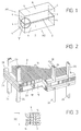
- FIG. 1 shows a schematic perspective view of two identical modules M1, M2 according to the invention, arranged one above the other, for a space cell construction, each of which has an essentially cuboid module structure.
- modules are assembled into a finished building.
- a single module comprises floor 2, wall 4 and ceiling elements 6, which are assembled into room cells.
- Floor, wall and ceiling elements are inherently stable for transport and installation. The same applies to the finished module made from these parts.
- buildings of larger size can be assembled in a demountable manner. The overall stability of such a structure results from articulated connections of the corner points of the individual modules. These connections are not shown in the drawings.
- FIG. 2 shows a schematic perspective view of an enlarged detail of the area of the two modules M1 and M2 arranged one above the other in FIG. 1 with the circle Y.
- the bottom element of the upper module M1 consists of a multilayer solid wood panel 8, which comprises a plurality of layers 10 arranged vertically and next to one another.
- the multi-layer solid wood panel 8 can also comprise a plurality of layers arranged horizontally one above the other.
- a design is also conceivable which represents a combination of layers arranged horizontally one above the other with layers arranged vertically and next to one another.
- the end faces of the multilayer solid wood panel 8 are provided with hem planks 28.
- Vertical planks 26 for the wall elements are in turn arranged on the hem planks 28.
- the planks 26 are stabilized against tilting, the hem planks 28 being placed between the vertical planks 26 and being fixed there.
- the wall elements are built in conventional construction as planked wooden stands or wooden frames or dissolved in supports with interchangeable beams. Furthermore, it is possible that the wall elements also have the construction method used for the floor element 8 described above.
- the wall elements can also be designed as load-bearing wall disks in order to implement column-free room cell closures.
- the wall elements contain installation lines and the like necessary for the module in this area within a facing shell (not shown). These installation lines are also not apparent from the drawings.
- the outer walls of the wall elements are insulated and ventilated.
- FIG. 2 also shows the structure of the ceiling element of the lower module M2.
- the ceiling element comprises vertically standing ceiling beams 18 which are tilt-stabilized by interposed and fixed planks 28.
- the planks 28 simultaneously form the hem planks located on the end face of the ceiling element.
- One or more ceiling panels 20, which are conventional mineral or wood-based panels, are fastened to the ceiling planks 18 and the planks 28.
- Floor, wall and ceiling elements of a module according to the invention can also be connected to one another by interlocking individual elements, thus reducing the structural strengths. Furthermore, it is possible to insert non-load-bearing elements, such as partition walls and the like, into the module.
- FIG. 3 shows a schematic sectional view of an enlarged detail of the multi-layer solid wood panel 8 shown in FIG. 2 of the floor element according to the invention.
- a single layer of the solid wood panel consists of a solid wood board 12.
- a large number of these solid wood boards 12 are connected to one another by means of mechanical connecting elements and thus form the multilayer solid wood panel 8.
- the mechanical connecting elements in the present case are nails 14, however, any other mechanical connecting elements suitable for the intended purpose can also be used.
- the layers of the solid wood panel 8 are glued. A combination of gluing and mechanical connecting means is also conceivable.
- the thickness of the multilayer solid wood panel 8 of the floor element of the module according to the invention identified by the reference symbol H in FIG. 3 is 12 cm in the present case, whereas a floor element in a conventional construction would result in approximately twice the value.
- the multilayer solid wood panel can also comprise one or more cavities, if this is necessary for installation purposes.
- Fig. 4 shows a second embodiment of a multilayer solid wood panel 8 of the bottom element of a module according to the invention.
- the multilayer solid wood panel 8 of the base element is provided with groove-like recesses 16 on its underside.
- these groove-like recesses 16 are formed by one or more layers 10.2 which are reduced in their vertical dimension compared to the other layers 10. If two identically designed modules M1 and M2 according to the invention are now arranged one above the other as shown in FIG. 1, the ceiling planks 18 of the lower module M2 protrude into the groove-like recesses 16 of the upper module M1.
- angled sheets 22 are also inserted in or between the layers 10 of the solid wood panel 8 and fixed there with suitable fastening elements 24, so that the vertical leg of the sheet 22 runs parallel to the layers 10 and the horizontal leg runs parallel to the bottom surface of the solid wood panel 8.
- the plates 22 serve to transmit thrust to a wall connection 30, which is firmly connected to the horizontal leg of the angled plate 22.
- the floor element in turn consists essentially of the multi-layer solid wood panel 8 and further comprises a screed covering 32 applied to the bottom surface of the solid wood panel 8 and a cover plate 34 located thereon.
- the bottom surface can be made up of a plurality of vertically and side by side arranged layers 10, 12 existing solid wood panel 8 have an irregular structure within a certain tolerance, since unevenness is compensated for by the applied screed 32 and the cover plate 34.
- the floor element comprises a plurality of multi-layer solid wood panels 8.2, 8.4 which form a complete one Floor element to be joined.
- the floor element comprises a plurality of multi-layer solid wood panels 8.2, 8.4 which form a complete one Floor element to be joined.
- These solid wood panels 8.2 and 8.4 each have corresponding adapters in the form of grooves 36 and projections 38, which simplify the positioning and assembly of the panels.
- the grooves 36 and the projections 38 are each arranged on an end face of the solid wood panel 8.2, 8.4.
- other suitable means such as multiple teeth or dovetail teeth and the like, can also be used as adapters.
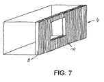
- Fig. 7 shows a schematic perspective view of a wall element 4 of a module according to the invention, the module outline being indicated only by simple lines.
- the wall element 4 consists of at least one multilayer solid wood panel 8, which comprises a plurality of vertically standing and adjacent layers 10.
- this arrangement of the individual layers in contrast to the known log house construction, allows the production of multi-storey buildings from several modules according to the invention arranged one above the other.
- the multi-layer solid wood panel 8 according to the invention is preferably made from side goods, whereby in the sense of the invention side material is to be understood as such a wood material that when producing boards with a rectangular cross section from essentially round tree trunks, the solid wood material remains that meets these geometric requirements of Boards are no longer enough.
- side material is to be understood as such a wood material that when producing boards with a rectangular cross section from essentially round tree trunks, the solid wood material remains that meets these geometric requirements of Boards are no longer enough.
- higher-quality woods can also be used for the production of the multilayer solid wood panel according to the invention.
- the free surfaces of the multi-layer solid wood panel can be rough sawn, planed, sanded or polished as required. With a very high-quality surface of the multi-layer solid wood panel 8, a parquet floor can thus be dispensed with, for example.
- stiffening frames or bandage elements can be inserted or clamped into the module or into its individual elements.
- Horizontal shear connections of modules placed on top of each other can be achieved using revolving centering planks or the like.
- the modules are bolted horizontally and vertically at the corner points and intermediate points with BVD connectors and welded steel cubes as intermediate pieces so that they are tension and pressure-resistant.
- Such connections are easy to assemble and allow the modules to be moved without great effort.
- the suspension points can also be equipped with BVD anchors and rigid truss frames, which ensure automatic level compensation.
- the modules or their individual elements can have their own steel rods, which are inserted horizontally and vertically through components and optionally pre-stressed, with intermediate brackets and sleeves that tilt and gap joints prevent.
Landscapes
- Engineering & Computer Science (AREA)
- Architecture (AREA)
- Physics & Mathematics (AREA)
- Electromagnetism (AREA)
- Civil Engineering (AREA)
- Structural Engineering (AREA)
- Floor Finish (AREA)
Applications Claiming Priority (2)
| Application Number | Priority Date | Filing Date | Title |
|---|---|---|---|
| DE19521990 | 1995-06-16 | ||
| DE1995121990 DE19521990C2 (de) | 1995-06-16 | 1995-06-16 | Raumzellen-Modul |
Publications (1)
| Publication Number | Publication Date |
|---|---|
| EP0748904A1 true EP0748904A1 (fr) | 1996-12-18 |
Family
ID=7764560
Family Applications (1)
| Application Number | Title | Priority Date | Filing Date |
|---|---|---|---|
| EP96109695A Withdrawn EP0748904A1 (fr) | 1995-06-16 | 1996-06-17 | Module pour système de construction à cellules préfabriquées |
Country Status (2)
| Country | Link |
|---|---|
| EP (1) | EP0748904A1 (fr) |
| DE (1) | DE19521990C2 (fr) |
Cited By (1)
| Publication number | Priority date | Publication date | Assignee | Title |
|---|---|---|---|---|
| EP0953697A3 (fr) * | 1998-03-31 | 1999-12-08 | A. Jandl Patentholding KEG | Maison |
Families Citing this family (1)
| Publication number | Priority date | Publication date | Assignee | Title |
|---|---|---|---|---|
| DE102020100374A1 (de) | 2020-01-09 | 2021-07-15 | Johannes Wolf | System zum Herstellen von Raumelementen |
Citations (3)
| Publication number | Priority date | Publication date | Assignee | Title |
|---|---|---|---|---|
| FR2190995A1 (fr) * | 1972-06-27 | 1974-02-01 | Senentz Roger | |
| DE3048360A1 (de) * | 1980-12-20 | 1982-07-01 | Lauri 44540 Soliskylä Vesterinen | Transportable raumzelle zum aufbau von haeusern in massivholzbauweise |
| EP0606633A2 (fr) * | 1993-04-23 | 1994-07-20 | Waldenburger Holzkabinett | Ensemble de blocs de construction en bois |
Family Cites Families (8)
| Publication number | Priority date | Publication date | Assignee | Title |
|---|---|---|---|---|
| GB1460111A (en) * | 1974-02-22 | 1976-12-31 | Galvagni M | Three-dimensional pre-fabricated structural elements to be assembled in habitation units |
| US4275533A (en) * | 1979-08-22 | 1981-06-30 | Wright Darold L | Portable building and method of transporting it |
| DE3229262C2 (de) * | 1982-08-05 | 1985-12-05 | Josef 8091 Soyen Griesbeck | Plattenförmiges Bauelement aus Holz |
| DE8800566U1 (de) * | 1988-01-19 | 1988-03-17 | Moser, Karl, 8890 Aichach | Konstruktionseinheit für ein Gebäude |
| DE3804525A1 (de) * | 1988-02-13 | 1989-08-24 | Wolfgang Schreiber | Saunawand aus blockbohlen |
| DE8901956U1 (de) * | 1989-02-18 | 1989-06-08 | Behrendt, Rudi, 2304 Lutterbek | Zerlegbare Notunterkunft |
| US5317857A (en) * | 1991-11-27 | 1994-06-07 | Allison Robert S | Standardized portable housing unit |
| DE4229719A1 (de) * | 1992-09-05 | 1994-03-10 | Bernhard Bley | Bauelementensatz für ein Gebäude |
-
1995
- 1995-06-16 DE DE1995121990 patent/DE19521990C2/de not_active Expired - Fee Related
-
1996
- 1996-06-17 EP EP96109695A patent/EP0748904A1/fr not_active Withdrawn
Patent Citations (3)
| Publication number | Priority date | Publication date | Assignee | Title |
|---|---|---|---|---|
| FR2190995A1 (fr) * | 1972-06-27 | 1974-02-01 | Senentz Roger | |
| DE3048360A1 (de) * | 1980-12-20 | 1982-07-01 | Lauri 44540 Soliskylä Vesterinen | Transportable raumzelle zum aufbau von haeusern in massivholzbauweise |
| EP0606633A2 (fr) * | 1993-04-23 | 1994-07-20 | Waldenburger Holzkabinett | Ensemble de blocs de construction en bois |
Non-Patent Citations (1)
| Title |
|---|
| ROBERT VON HALÁSZ ET AL: "Holzbau-Taschenbuch", 1986, ERNST & SOHN VERLAG FÜR ARCHITEKTEUR UND TECHNISCHE WISSENSCHAFT, BERLIN, XP002014562 * |
Cited By (1)
| Publication number | Priority date | Publication date | Assignee | Title |
|---|---|---|---|---|
| EP0953697A3 (fr) * | 1998-03-31 | 1999-12-08 | A. Jandl Patentholding KEG | Maison |
Also Published As
| Publication number | Publication date |
|---|---|
| DE19521990A1 (de) | 1996-12-19 |
| DE19521990C2 (de) | 2000-01-13 |
Similar Documents
| Publication | Publication Date | Title |
|---|---|---|
| AT406596B (de) | Vorgefertigtes schichtholzelement | |
| EP2099978B1 (fr) | Système de construction pour bâtiments | |
| EP0560013B1 (fr) | Panneau en bois | |
| EP1734200B1 (fr) | Utilisation d'un élément de paroi pour un bâtiment et d'un un elément composite de bois | |
| AT522516B1 (de) | Raum-Modul, aus Raum-Modulen hergestelltes Gebäude, sowie jeweils ein Herstellverfahren hierfür | |
| EP0593984B1 (fr) | Elément de construction de paroi et paroi réalisée à partir de cet élément de construction | |
| CH687884A5 (de) | Holzbautafel. | |
| AT511169A1 (de) | Modulares gebäude | |
| DE19521990C2 (de) | Raumzellen-Modul | |
| EP2256262B1 (fr) | Module de bâtiment en bois, son utilisation et son procédé de fabrication | |
| AT503225B1 (de) | Holzbautafel | |
| DE29618522U1 (de) | Bausatz für ein Fertigteilhaus | |
| DE29509801U1 (de) | Modul für Raumzellenbauweise | |
| DE10006492A1 (de) | Haus mit Fertigbauelementen für den leicht handhabbaren Eigenbau | |
| DE3309645A1 (de) | Bautafel aus holz sowie gebaeude aus vorgefertigten holzbauteilen | |
| DE9311437U1 (de) | Bausatz fuer fachwerkbauten | |
| DE19739402C2 (de) | Gebäudeecke für ein Haus in Holzbauweise | |
| EP3067483B1 (fr) | Montage de mur pour un système de bâtiment, en particulier un immeuble d'habitation | |
| DE8330832U1 (de) | Gebaeude aus vorgefertigten holzbauteilen | |
| CH697249B1 (de) | Holzbauelement. | |
| DE19714792A1 (de) | Fertighaus und vorgefertigtes Element hierfür | |
| DE102015118975A1 (de) | Bausatz aus Bauelementen zum Herstellen eines Gebäudes und Verfahren zum Herstellen eines Gebäudes | |
| DE102022111477A1 (de) | Mehr-Raum-Einheit | |
| DE10025767A1 (de) | Bausatz für ein Fachwerkhaus | |
| DE8307873U1 (de) | Bautafel aus holz |
Legal Events
| Date | Code | Title | Description |
|---|---|---|---|
| PUAI | Public reference made under article 153(3) epc to a published international application that has entered the european phase |
Free format text: ORIGINAL CODE: 0009012 |
|
| 17P | Request for examination filed |
Effective date: 19960617 |
|
| AK | Designated contracting states |
Kind code of ref document: A1 Designated state(s): AT CH DE DK FI FR LI NL SE |
|
| 17Q | First examination report despatched |
Effective date: 19990601 |
|
| STAA | Information on the status of an ep patent application or granted ep patent |
Free format text: STATUS: THE APPLICATION IS DEEMED TO BE WITHDRAWN |
|
| 18D | Application deemed to be withdrawn |
Effective date: 19991012 |