EP0748954B1 - Stellkoppelgetriebe - Google Patents
Stellkoppelgetriebe Download PDFInfo
- Publication number
- EP0748954B1 EP0748954B1 EP96109102A EP96109102A EP0748954B1 EP 0748954 B1 EP0748954 B1 EP 0748954B1 EP 96109102 A EP96109102 A EP 96109102A EP 96109102 A EP96109102 A EP 96109102A EP 0748954 B1 EP0748954 B1 EP 0748954B1
- Authority
- EP
- European Patent Office
- Prior art keywords
- output
- input
- shaft
- adjusting coupling
- transmission according
- Prior art date
- Legal status (The legal status is an assumption and is not a legal conclusion. Google has not performed a legal analysis and makes no representation as to the accuracy of the status listed.)
- Expired - Lifetime
Links
Images


Classifications
-
- F—MECHANICAL ENGINEERING; LIGHTING; HEATING; WEAPONS; BLASTING
- F16—ENGINEERING ELEMENTS AND UNITS; GENERAL MEASURES FOR PRODUCING AND MAINTAINING EFFECTIVE FUNCTIONING OF MACHINES OR INSTALLATIONS; THERMAL INSULATION IN GENERAL
- F16H—GEARING
- F16H37/00—Combinations of mechanical gearings, not provided for in groups F16H1/00 - F16H35/00
- F16H37/02—Combinations of mechanical gearings, not provided for in groups F16H1/00 - F16H35/00 comprising essentially only toothed or friction gearings
- F16H37/06—Combinations of mechanical gearings, not provided for in groups F16H1/00 - F16H35/00 comprising essentially only toothed or friction gearings with a plurality of driving or driven shafts; with arrangements for dividing torque between two or more intermediate shafts
- F16H37/08—Combinations of mechanical gearings, not provided for in groups F16H1/00 - F16H35/00 comprising essentially only toothed or friction gearings with a plurality of driving or driven shafts; with arrangements for dividing torque between two or more intermediate shafts with differential gearing
- F16H37/0833—Combinations of mechanical gearings, not provided for in groups F16H1/00 - F16H35/00 comprising essentially only toothed or friction gearings with a plurality of driving or driven shafts; with arrangements for dividing torque between two or more intermediate shafts with differential gearing with arrangements for dividing torque between two or more intermediate shafts, i.e. with two or more internal power paths
- F16H37/084—Combinations of mechanical gearings, not provided for in groups F16H1/00 - F16H35/00 comprising essentially only toothed or friction gearings with a plurality of driving or driven shafts; with arrangements for dividing torque between two or more intermediate shafts with differential gearing with arrangements for dividing torque between two or more intermediate shafts, i.e. with two or more internal power paths at least one power path being a continuously variable transmission, i.e. CVT
- F16H37/0846—CVT using endless flexible members
-
- F—MECHANICAL ENGINEERING; LIGHTING; HEATING; WEAPONS; BLASTING
- F16—ENGINEERING ELEMENTS AND UNITS; GENERAL MEASURES FOR PRODUCING AND MAINTAINING EFFECTIVE FUNCTIONING OF MACHINES OR INSTALLATIONS; THERMAL INSULATION IN GENERAL
- F16H—GEARING
- F16H9/00—Gearings for conveying rotary motion with variable gear ratio, or for reversing rotary motion, by endless flexible members
- F16H9/02—Gearings for conveying rotary motion with variable gear ratio, or for reversing rotary motion, by endless flexible members without members having orbital motion
- F16H9/04—Gearings for conveying rotary motion with variable gear ratio, or for reversing rotary motion, by endless flexible members without members having orbital motion using belts, V-belts, or ropes
- F16H9/12—Gearings for conveying rotary motion with variable gear ratio, or for reversing rotary motion, by endless flexible members without members having orbital motion using belts, V-belts, or ropes engaging a pulley built-up out of relatively axially-adjustable parts in which the belt engages the opposite flanges of the pulley directly without interposed belt-supporting members
- F16H9/16—Gearings for conveying rotary motion with variable gear ratio, or for reversing rotary motion, by endless flexible members without members having orbital motion using belts, V-belts, or ropes engaging a pulley built-up out of relatively axially-adjustable parts in which the belt engages the opposite flanges of the pulley directly without interposed belt-supporting members using two pulleys, both built-up out of adjustable conical parts
- F16H2009/163—Arrangements of two or more belt gearings mounted in parallel, e.g. for increasing transmittable torque
-
- F—MECHANICAL ENGINEERING; LIGHTING; HEATING; WEAPONS; BLASTING
- F16—ENGINEERING ELEMENTS AND UNITS; GENERAL MEASURES FOR PRODUCING AND MAINTAINING EFFECTIVE FUNCTIONING OF MACHINES OR INSTALLATIONS; THERMAL INSULATION IN GENERAL
- F16H—GEARING
- F16H37/00—Combinations of mechanical gearings, not provided for in groups F16H1/00 - F16H35/00
- F16H37/02—Combinations of mechanical gearings, not provided for in groups F16H1/00 - F16H35/00 comprising essentially only toothed or friction gearings
- F16H37/06—Combinations of mechanical gearings, not provided for in groups F16H1/00 - F16H35/00 comprising essentially only toothed or friction gearings with a plurality of driving or driven shafts; with arrangements for dividing torque between two or more intermediate shafts
- F16H37/08—Combinations of mechanical gearings, not provided for in groups F16H1/00 - F16H35/00 comprising essentially only toothed or friction gearings with a plurality of driving or driven shafts; with arrangements for dividing torque between two or more intermediate shafts with differential gearing
- F16H37/0833—Combinations of mechanical gearings, not provided for in groups F16H1/00 - F16H35/00 comprising essentially only toothed or friction gearings with a plurality of driving or driven shafts; with arrangements for dividing torque between two or more intermediate shafts with differential gearing with arrangements for dividing torque between two or more intermediate shafts, i.e. with two or more internal power paths
- F16H37/084—Combinations of mechanical gearings, not provided for in groups F16H1/00 - F16H35/00 comprising essentially only toothed or friction gearings with a plurality of driving or driven shafts; with arrangements for dividing torque between two or more intermediate shafts with differential gearing with arrangements for dividing torque between two or more intermediate shafts, i.e. with two or more internal power paths at least one power path being a continuously variable transmission, i.e. CVT
- F16H2037/088—Power-split transmissions with summing differentials, with the input of the CVT connected or connectable to the input shaft
Definitions
- the invention relates to an adjusting coupling transmission with the features according to the preamble of claim 1.
- the invention further relates to an adjusting coupling gear the features according to the preamble of claim 2.
- the input power can in the first branch directly onto the planet gear and in the other branch via the continuously adjustable Transfer actuator to the ring gear of the planetary gear become.
- the output of the actuating coupling gear then forms that Sun gear or the sun gear shaft of the planetary gear.
- the invention is based on the object of actuating coupling gears of the type mentioned at the outset, that while maintaining the benefits achievable with it (large translation range, possibility of reversing the direction of rotation, low-loss operation in the most common operating modes in practice, stepless variation of the output speed below Load, high efficiency and cost-effective production) Construction is achieved in which impermissibly high speeds avoided become.
- a planetary sum gear is thus used in the the input power is divided into two power paths. While the first power path e.g. over a non-rotatable attached to the input shaft attached variator, which the Force on a wide V-belt transmits the transmission, the second power share is over a constant drive with a fixed ratio in the transmission headed. It is preferred if the variator is a belt transmission with adjustable pulleys, which is more preferred is driven directly by the input shaft. If the Constant drive is a belt drive with fixed pulleys, can have both an adjustable and a fixed pulley each be arranged in a rotationally fixed manner on the input shaft.
- the couplings are operable, preferably by the couplings in the transition point between two ranges of the output speed or when starting can be operated alternatively.
- the second Area bridges the planetary sum gear while at a second variant, the planetary sum gear in the second Area revolves as a closed block.
- the output speeds can be divided into two areas, namely in a power-split and a non-power split Area.
- the two areas are linked by the two couplings, where both clutches at the same speed of the first and of the second area are switchable under load.
- the second Coupling couples the variable power path via the variator, the first clutch couples the constant power path.
- both clutches can also be used for a short time be switched.
- By loosening one or the other Clutch can be under load and without between the two areas Traction interruption can be switched back and forth.
- Another advantage is that the couplings can be designed as positive couplings, so in a relatively simple and inexpensive design.
- both clutches are open, and the Variator is automatically controlled so that the gearbox output speed Is zero. Then the first clutch for the Constant drive closed and the output speed to one Value regulated from zero.
- This measure has the advantage that to start one of Gearbox driven unit not from zero speed in the variator, but rather a finite speed can be assumed, so that the variator with running belts in the area of its highest power density.
- the output speed of the output shaft stepless from positive to zero to negative speeds is adjustable.
- a transmission designed according to the invention can be used both as continuously variable primary transmission for travel drives in vehicles as well as a continuously variable transmission for driving machine components, for example a threshing drum in one Combine harvesters.
- vehicles with a Gears according to the invention are equipped, it is possible at constant (optimal) engine speed, the gear ratio steplessly regulated and maneuvered under load (forward and to reverse) without clutching or preselecting gears have to.
- the gear ratio steplessly regulated and maneuvered under load forward and to reverse
- clutching or preselecting gears have to.
- When realizing the main work area in the non-performance-split The range can otherwise be in a summation gear reactive powers are avoided. To this An economical operation of the vehicle or the Machine possible.
- the transmission according to the invention When designing the transmission according to the invention as a planetary planetary gear are two pairs of gears, each with two meshing gears provided. There is one of each Gear rotatably arranged on a web shaft, while the each other gear rotatably with the first input path forming input shaft or one forming the output Output shaft is connected. Furthermore, the web shaft is rotatable stored in a web housing. The bridge housing is non-rotatable connected to a hollow shaft forming the second input path. For example, a planetary double wheel would also be possible is rotatably mounted on the non-rotatable web shaft.
- the variator When designing of the transmission according to the invention as a planetary ring gear the variator is connected to the ring gear.
- the couplings for the variator and the constant drive act when actuated on the web shaft guided through the ring gear, which is connected to the Planet gear is connected while the output shaft is on the sun gear the planetary gear set is attached.
- a small variator control range is possible with the planetary gear types described here.
- this value can also be deviated up or down.
- the implementation of the required gear ratio is easier with a planetary epicyclic gear because, compared to the planetary ring gear, you have greater freedom in choosing the gear ratio.
- the fundamental goal of striving for a small variator control range, since this has a higher power density, is easier to achieve in the planetary epicyclic gearbox.
- a high power density is understood here to mean a variator which, due to the smaller control range, has larger small diameters and, with fixed outer diameters, a narrow upper belt width with a large belt height and usual output speeds so that the belt does not deflect transversely to the direction of travel when the belt is subjected to high loads can.
- planetary planetary gears there is the additional advantage that the speeds of the planet gears can be lower than in most planetary gears with a ring gear.
- the variator speed at Reverse direction of rotation to increase the negative output speed reduced so far that it changes with the speed of the Constant drive matches can be described in the above Way by actuating the clutches in the planetary sum gear from the power split to the non power split Range can be switched in which then no reactive power occur more.
- Fig. 1 10 designates a total of an actuating coupling gear.
- Gearbox input 12 symbolized by an arrow is indicated by an input shaft 13 is formed.
- a belt drive 14 with constant Gear ratio has a first pulley 15, one second pulley 16 and a belt that wraps around it 17 on.
- the first pulley 15 is non-rotatable with the input shaft 13 connected.
- the second pulley 16 is seated a loose bearing on an intermediate shaft 21.
- the intermediate shaft 21 extends parallel to the input shaft 13.
- a first clutch 25 the second pulley 16 in rotatably connected to the intermediate shaft 21 are brought.
- a variator 30 with a continuously adjustable transmission ratio is in the adjusting coupling gear 10 according to FIG. 1 as Belt gear trained.
- the variator 30 has a first Pulley 31, a second pulley 32 and one of these looping belt 33.
- the first pulley 31 is also arranged in a rotationally fixed manner on the input shaft 13.
- the second pulley 32 of the variator is seated 30 on a hollow shaft 40 which surrounds an output shaft 41.
- the hollow shaft 40 and the output shaft 41 also run parallel to the input shaft 13. They are also coaxial arranged to the intermediate shaft 21.
- the epicyclic gear 47 has a web housing 48.
- the web housing 48 is on its left side in Fig. 1 rotatably with the hollow shaft 40 connected.
- a web shaft 49 is rotatably mounted in the web housing 48 or a planetary double gear 52/53 rotatable on the non-rotating Web shaft 49 mounted.
- the intermediate shaft 21 rotatably supports a first gear 51 which meshes with a second gear 52 which is non-rotatably fastened on the web shaft 49.
- a third gear 53 which is also non-rotatably connected to the web shaft 49, meshes with a fourth gear 54, which is arranged in a rotationally fixed manner on the output shaft 41.
- two wheel sets are formed, namely by the first and second gear 51/52 and by the third and fourth gear 53/54.
- the associated number of teeth of the four gear wheels 51 to 54 are designated in FIG. 1 with Z 1 to Z 4 .
- the adjusting coupling gear 10 according to FIG. 1 is shown again schematically in FIG. 2. It is also the speed of the second pulley 16 of the belt drive 14 referred to as the input speed n of the speed of the hollow shaft 40 as the variator var n and the speed of the output shaft 41. Finally, as output speed n.
- FIG. 3 shows a diagram in which the variator speed n var is plotted on the ordinate and the output speed n ab on the abscissa.
- the two axes are parameterized with speed values that were taken from a realized embodiment of the invention. These numbers are therefore to be understood only as examples and do not limit the scope of the present invention.
- the rotational speed profile is divided based on the output rotational speed n from a power split in the area A and a non-power-split range B, which are speed curves a and b associated.
- a power split in the area A In area A, the first clutch 25 is closed and the second clutch 45 is opened. In area B, however, the first clutch 25 is open and the second clutch 45 is closed.
- the input power is thus transmitted as follows:
- the input power is branched.
- a first part of the input power flows from the input shaft 13 via the belt drive 14 and the closed first clutch 25 to the intermediate shaft 21 and from there via the gear ratio Z 1 / Z 2 of the gear wheels 51, 52 to the web shaft 49.
- the intermediate shaft 21 thus serves as the first input of epicyclic gear 47, which acts as a summation gear.
- the second power component flows via the input shaft 13 and the variator 30 on the hollow shaft 40.
- the hollow shaft 40 drives the web housing 48 and thus the web shaft 49.
- the hollow shaft 40 is thus the second input of the one acting as a summation gear Epicyclic gear 47.
- the output speed n from the second pulley 32 have the variator and the output shaft 41 just the same speed, as well as the intermediate shaft 21 and the second pulley 16 of the belt drive 14 have the same speed.
- the clutches 25 and 45 can thus be switched over without load. This makes it possible to design the couplings 25, 45 as simple form-fitting couplings, for example as tooth, cams or claw couplings.
- the constant input speed was chosen so that it corresponds to the minimum variator output speed n var of, for example, 1,000 min -1 .
- area B is the main work area can be used in which the epicyclic gear 47 except Function is.
- This area B is comparable to conventional ones Areas of application of variators.
- the area A is used for lowering the output speed n from below 1,000 min -1 to 0 min -1 and for starting at zero speed and for maneuvering at zero speed. Reversing is possible up to an output speed n from -1,234 min -1 .
- area A serves to lower the output speed n ab and for reversing.
- both clutches 25 and 45 must first be opened.
- the variator speed n var changes the driven unit now starts up.
- the reversing gear 55 comprises a first gear set 56 with two Gears and a second gear set 57 with three gears. Via the first wheel set 56, the output of the actuating coupling gear can 10 in the forward direction R and over the second wheel set 57 are operated in the reverse direction V. An output wave 58 of the reversing gear 55 also forms the one with an arrow indicated transmission output 59.
- Fig. 4 is the representation in a representation similar to Fig. 3 Speed diagram shown, which is when using the Reverse gear 55 sets.
- non-power-branched areas B 1 and B 2 there are two associated non-power-branched areas B 1 and B 2 .
- the first clutch 25 is closed, while in the non-power split areas B 1 and B 2, the second clutch 45 is closed.
- the output speed in the power-split region A changes from zero to the value +1,000 min -1 , while at the same time the variator speed from +1,538 min -1 to 1,000 min - 1 drops.
- the output speed n increases from then on from +1.000 +2300 min -1, while at the same time the variator speed of 1000 min -1 is increased at 2.300 min -1.
- the reversing gear 55 can be opened when the output speed n ab is zero.
- the variator speed is then +1,583 min -1 .
- the reversing gear 55 is open, it is possible to switch from the forward direction V to the reverse direction R or vice versa.
- Fig. 4 shows that the full speed range from -2300 to +2300 min -1 to output speed n can be traversed from continuously.
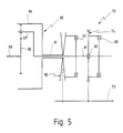
- FIG. 5 shows a variant of an actuating coupling gear 70 that according to the adjusting coupling gear 10 Figures 1 and 2 is modified.
- the input power can initially be from an input shaft 73 to a belt drive 74 with a constant transmission ratio be transmitted.
- the belt drive 74 sits with a loose Bearing 80 on an intermediate shaft 81.
- a first Coupling 85 can be the loose belt pulley of the belt drive 74 are rotatably connected to the intermediate shaft 81.
- Power from input shaft 73 can also be applied to a variator 90 can be transmitted with a variable transmission ratio.
- the Variator 90 is rotatably arranged on a hollow shaft 91.
- a second clutch 92 By means of a second clutch 92, the on the hollow shaft 91 attached pulley of the variator 90 rotatably with the Intermediate shaft 81 are connected.
- a planetary ring gear 95 has a ring gear 96, one Web 97 and a sun gear 98 on.
- An output shaft is 99 non-rotatably connected to the sun gear 98. It stretches in extension of the intermediate shaft 81, on which the concentric Hollow shaft 91 sits.
- the ring gear 96 is rotationally fixed to the hollow shaft 91, and the web 97 is rotationally fixed to the intermediate shaft 81 connected.
- the actuating coupling gear 70 according to FIG. 5 operates as follows:
- the second clutch is in non-power-split operation 92 closed. Then over the hollow shaft 91, which is on the Hollow shaft 91 attached pulley of the variator 90, the second clutch 92 and the intermediate shaft 81, the ring gear 96 non-rotatably connected to the web 97. The planetary ring gear 95 then circulates as a fixed block. The input power will then directly from the input shaft 73 via the variator 90 transferred to the output shaft 99.
- the planetary ring gear 95 acts now as a sum gear.
- Part of the input shaft 73 fed input power of the actuating coupling gear 70 is now via the belt drive 74, the closed first clutch 85 and the intermediate shaft 81 transferred to the web 97.
- On the second part of the input power comes through the variator 90 and the hollow shaft 91 on the ring gear 96.
- the two power components are summed up again and the sum of the sun gear 98 and the output shaft 99 fed.
- the function of the actuating coupling gear corresponds 70 the function of the adjusting coupling gear 10 according to the figures 1 and 2, so that the ratios of the speed diagram 3 are retained.
- FIG. 5 is also with a Reverse gear connected at the output (see Fig. 2), see above a speed diagram similar to that of FIG. 4 is produced.
Landscapes
- Engineering & Computer Science (AREA)
- General Engineering & Computer Science (AREA)
- Mechanical Engineering (AREA)
- Transmission Devices (AREA)
Applications Claiming Priority (2)
| Application Number | Priority Date | Filing Date | Title |
|---|---|---|---|
| DE19521486A DE19521486B4 (de) | 1995-06-13 | 1995-06-13 | Stellkoppelgetriebe |
| DE19521486 | 1995-06-13 |
Publications (3)
| Publication Number | Publication Date |
|---|---|
| EP0748954A2 EP0748954A2 (de) | 1996-12-18 |
| EP0748954A3 EP0748954A3 (de) | 1998-03-18 |
| EP0748954B1 true EP0748954B1 (de) | 2000-12-27 |
Family
ID=7764269
Family Applications (1)
| Application Number | Title | Priority Date | Filing Date |
|---|---|---|---|
| EP96109102A Expired - Lifetime EP0748954B1 (de) | 1995-06-13 | 1996-06-06 | Stellkoppelgetriebe |
Country Status (4)
| Country | Link |
|---|---|
| US (1) | US5820508A (da) |
| EP (1) | EP0748954B1 (da) |
| DE (2) | DE19521486B4 (da) |
| DK (1) | DK0748954T3 (da) |
Cited By (1)
| Publication number | Priority date | Publication date | Assignee | Title |
|---|---|---|---|---|
| DE19521486B4 (de) * | 1995-06-13 | 2007-06-21 | Claas Kgaa Mbh | Stellkoppelgetriebe |
Families Citing this family (30)
| Publication number | Priority date | Publication date | Assignee | Title |
|---|---|---|---|---|
| JP3217285B2 (ja) * | 1996-12-06 | 2001-10-09 | バンドー化学株式会社 | 車両用無段変速機及びそれを用いた芝刈り用トラクタ |
| DE19728611A1 (de) | 1997-07-04 | 1999-02-04 | Zahnradfabrik Friedrichshafen | Stufenloses Getriebe |
| DE19728610A1 (de) * | 1997-07-04 | 1999-02-04 | Zahnradfabrik Friedrichshafen | Stufenloses Getriebe |
| KR19990024503A (ko) * | 1997-09-03 | 1999-04-06 | 문병일 | 변속비 폭이 넓은 무단변속장치 |
| IT1319855B1 (it) * | 2000-02-22 | 2003-11-03 | Same Deutz Fahr Spa | Trasmissione idromeccanica a rapporto variabile in modo continuo. |
| US6609368B2 (en) | 2001-06-04 | 2003-08-26 | Caterpillar S.A.R.L. | Automatic downshift and override control for a transmission |
| US7062368B2 (en) * | 2002-06-11 | 2006-06-13 | Cnh America Llc | Combine having a system estimator to automatically estimate and dynamically change a target control parameter in a control algorithm |
| DE102005022012A1 (de) * | 2005-05-12 | 2006-12-07 | Daimlerchrysler Ag | Getriebe für ein Kraftfahrzeug mit stufenlosen leistungsverzweigten Fahrbereichen |
| US20080103006A1 (en) * | 2006-10-30 | 2008-05-01 | Sauer-Danfoss Inc. | Hydromechanical transmission with input summer |
| US20080171626A1 (en) * | 2007-01-16 | 2008-07-17 | Sauer-Danfoss Inc. | Hydromechanical transmission with output summer |
| DE102007053436A1 (de) * | 2007-11-07 | 2009-05-14 | Claas Selbstfahrende Erntemaschinen Gmbh | Motorregelung einer selbstfahrenden Arbeitsmaschine |
| TWI482921B (zh) * | 2008-02-01 | 2015-05-01 | Tai Her Yang | 多檔並聯傳動之多級無段變速傳動裝置 |
| DE102008021010B4 (de) * | 2008-04-25 | 2010-02-25 | Lohmann & Stolterfoht Gmbh | Leistungsverzweigungsgetriebe |
| WO2010118721A1 (de) * | 2009-04-14 | 2010-10-21 | Schaeffler Technologies Gmbh & Co. Kg | Getriebeeinheit mit einem stufenlos verstellbaren getriebe |
| US9169909B2 (en) * | 2009-11-24 | 2015-10-27 | Tai-Her Yang | Stepless variable transmission device with parallel low gear wheel group |
| US8578802B2 (en) * | 2009-12-16 | 2013-11-12 | Allison Transmission, Inc. | System and method for multiplexing gear engagement control and providing fault protection in a toroidal traction drive automatic transmission |
| US8401752B2 (en) | 2009-12-16 | 2013-03-19 | Allison Transmission, Inc. | Fail-to-neutral system and method for a toroidal traction drive automatic transmission |
| EP2513516B1 (en) * | 2009-12-16 | 2017-05-31 | Allison Transmission, Inc. | Variator lockout valve system |
| CN102713351B (zh) * | 2009-12-16 | 2016-06-29 | 艾里逊变速箱公司 | 用于控制变速机构端负载作用力的系统和方法 |
| CA2784764C (en) * | 2009-12-16 | 2019-03-12 | Allison Transmission, Inc. | Variator fault detection system |
| CA2784373C (en) | 2009-12-16 | 2017-11-07 | Allison Transmission, Inc. | Fast valve actuation system for an automatic transmission |
| WO2012024225A1 (en) | 2010-08-16 | 2012-02-23 | Allison Transmission, Inc. | Gear scheme for infinitely variable transmission |
| US8727942B2 (en) | 2010-12-15 | 2014-05-20 | AllisonTransmission, Inc. | Dual pump regulator system for a motor vehicle transmission |
| CA2821956C (en) | 2010-12-15 | 2018-09-11 | Allison Transmission, Inc. | Variator multiplex valve scheme for a toroidal traction drive transmission |
| EP2655938A4 (en) | 2010-12-15 | 2016-07-27 | Allison Transm Inc | DRIVE SWITCHING VALVE PROGRAM FOR TORONTO TRACTION DRIVE TRANSMISSION |
| DE102011114627A1 (de) | 2011-09-30 | 2013-04-04 | Claas Selbstfahrende Erntemaschinen Gmbh | Mähdrescher |
| US9248820B2 (en) | 2011-12-09 | 2016-02-02 | Dana Belgium N.V. | Shifting procedure for powersplit systems |
| CN103291856B (zh) * | 2013-06-13 | 2018-08-24 | 广西玉柴农业装备有限公司 | 与微耕机配套的传动装置 |
| DE102014001610A1 (de) | 2014-02-10 | 2015-08-27 | Claas Selbstfahrende Erntemaschinen Gmbh | Mähdrescher und Planetengetriebe dafür |
| US9377084B2 (en) * | 2014-07-31 | 2016-06-28 | GM Global Technology Operations LLC | Automated manual transmission with dynamic torque transfer device |
Family Cites Families (36)
| Publication number | Priority date | Publication date | Assignee | Title |
|---|---|---|---|---|
| US2852130A (en) * | 1953-10-26 | 1958-09-16 | Us Electrical Motors Inc | Uniform tension winding mechanism |
| US3152490A (en) * | 1962-11-13 | 1964-10-13 | Ford Motor Co | Infinitely variable drive transmission |
| FR1440883A (fr) * | 1964-05-02 | 1966-06-03 | Zahnradfabrik Friedrichshafen | Système de transmission |
| GB1128694A (en) * | 1966-04-06 | 1968-10-02 | Deere & Co | Combined variable-speed and planetary drive |
| DE1625030A1 (de) * | 1966-04-08 | 1970-02-05 | Deere & Co | Umlaufraederwechselgetriebe,insbesondere fuer landwirtschaftlich nutzbare Motorfahrzeuge |
| US3939732A (en) * | 1973-05-10 | 1976-02-24 | Sira Societa Industriale Richerche Automotoristiche | Power unit for vehicles incorporating an automatic stepless speed change gear |
| US4056987A (en) * | 1974-11-20 | 1977-11-08 | Georges Hoffmann | Mechanism for parallel connection of infinitely-adjustable looping gearings |
| DE2621682A1 (de) * | 1976-05-15 | 1977-11-24 | Zahnradfabrik Friedrichshafen | Stufenlos verstellbares kegelscheiben-umschlingungsgetriebe |
| DE2961626D1 (en) * | 1978-01-21 | 1982-02-18 | Piv Antrieb Reimers Kg Werner | Continuously variable transmission mechanisms |
| JPS5649452A (en) * | 1979-09-28 | 1981-05-06 | Toyota Motor Corp | Stepless speed change machine |
| JPS5649458A (en) * | 1979-09-28 | 1981-05-06 | Toyota Motor Corp | Stepless speed change machine |
| JPS5649454A (en) * | 1979-09-28 | 1981-05-06 | Toyota Motor Corp | Stepless speed change machine |
| DE2948681A1 (de) * | 1979-12-04 | 1981-06-11 | P.I.V. Antrieb Werner Reimers Kg, 6380 Bad Homburg | Getriebeanordnung insbesondere fuer kraftfahrzeuge |
| US4409862A (en) * | 1981-03-23 | 1983-10-18 | Adkins John S | Variable speed rotary power transmission |
| DE3124070A1 (de) * | 1981-06-11 | 1983-01-05 | Vauxhall Motors Ltd., Luton, Bedfordshire | Getriebe mit veraenderlicher uebersetzung |
| US4402237A (en) * | 1981-06-29 | 1983-09-06 | General Motors Corporation | Variable ratio power transmission mechanisms |
| US4458558A (en) * | 1981-08-05 | 1984-07-10 | Aisin Seiki Kabushiki Kaisha | Variable V-belt type continuously variable transmission for vehicles |
| DE3147447C2 (de) * | 1981-12-01 | 1984-06-14 | Jarchow, Friedrich, Prof. Dr.-Ing., 4300 Essen | Hydrostatischmechanisches Stellkoppelgetriebe mit eingangsseitiger Leistungsverzweigung |
| FR2522100B1 (fr) * | 1982-02-22 | 1987-04-24 | Valeo | Transmission entre une prise de mouvement et un arbre recepteur, notamment pour vehicule automobile |
| JPS59164448A (ja) * | 1983-03-10 | 1984-09-17 | Aisin Seiki Co Ltd | 無段変速装置 |
| JPS60116959A (ja) * | 1983-11-28 | 1985-06-24 | Toyota Central Res & Dev Lab Inc | 車輛用無段変速装置 |
| AU4570585A (en) * | 1984-08-27 | 1986-03-06 | Borg-Warner Corporation | Continuously variable transmission with synchronous shift and extended range |
| DE3538343A1 (de) * | 1984-11-02 | 1986-05-15 | Volkswagen AG, 3180 Wolfsburg | Getriebeanordnung fuer fahrzeuge, insbesondere kraftfahrzeuge |
| DE3543635A1 (de) * | 1984-12-18 | 1986-06-19 | Volkswagen AG, 3180 Wolfsburg | Getriebeanordnung |
| US4644820A (en) * | 1986-02-03 | 1987-02-24 | General Motors Corporation | Geared-neutral continuously variable transmission |
| DE3926794A1 (de) * | 1989-08-14 | 1991-02-21 | Kriegler Franz | Stufenloses getriebe |
| US4990127A (en) * | 1989-10-17 | 1991-02-05 | Borg-Warner Automotive, Inc. | Dual range infinitely variable transmission |
| DE4107739A1 (de) * | 1990-03-15 | 1991-09-19 | Zahnradfabrik Friedrichshafen | Getriebeaggregat fuer kraftfahrzeuge mit einem stufenlos regelbaren zugorgangetriebe |
| US5055094A (en) * | 1990-03-21 | 1991-10-08 | General Motors Corporation | Continuously variable transmission |
| US5292290A (en) * | 1991-12-16 | 1994-03-08 | Volkswagen Ag | Transmission arrangement for vehicles |
| IT1254653B (it) * | 1992-03-02 | 1995-09-28 | Struttura di gruppo a diramazione di potenza particolarmente per macchine agricole, industriali e simili | |
| DE4308761A1 (de) * | 1993-03-19 | 1994-09-22 | Zahnradfabrik Friedrichshafen | Stufenlos variables Getriebe mit großer Übersetzungsspreizung |
| JP3588805B2 (ja) * | 1993-06-23 | 2004-11-17 | 井関農機株式会社 | コンバインの走行伝動装置 |
| IN189939B (da) * | 1993-12-20 | 2003-05-17 | Torotrak Dev Ltd | |
| DE9418267U1 (de) * | 1994-01-18 | 1995-02-16 | Nießing Stahlbau- Stahlschornsteinbau GmbH, 46325 Borken | Getriebe für ein Kraftwerk |
| DE19521486B4 (de) * | 1995-06-13 | 2007-06-21 | Claas Kgaa Mbh | Stellkoppelgetriebe |
-
1995
- 1995-06-13 DE DE19521486A patent/DE19521486B4/de not_active Expired - Fee Related
-
1996
- 1996-06-06 EP EP96109102A patent/EP0748954B1/de not_active Expired - Lifetime
- 1996-06-06 DE DE59606244T patent/DE59606244D1/de not_active Expired - Fee Related
- 1996-06-06 DK DK96109102T patent/DK0748954T3/da active
- 1996-06-12 US US08/662,202 patent/US5820508A/en not_active Expired - Fee Related
Cited By (1)
| Publication number | Priority date | Publication date | Assignee | Title |
|---|---|---|---|---|
| DE19521486B4 (de) * | 1995-06-13 | 2007-06-21 | Claas Kgaa Mbh | Stellkoppelgetriebe |
Also Published As
| Publication number | Publication date |
|---|---|
| US5820508A (en) | 1998-10-13 |
| EP0748954A3 (de) | 1998-03-18 |
| DE19521486B4 (de) | 2007-06-21 |
| DE19521486A1 (de) | 1996-12-19 |
| EP0748954A2 (de) | 1996-12-18 |
| DE59606244D1 (de) | 2001-02-01 |
| DK0748954T3 (da) | 2001-04-30 |
Similar Documents
| Publication | Publication Date | Title |
|---|---|---|
| EP0748954B1 (de) | Stellkoppelgetriebe | |
| DE2757300C2 (de) | Leistungsverzweigtes hydrostatisch-mechanisches Verbundgetriebe | |
| DE2757191C2 (de) | Stufenlos einstellbares hydrostatisch-mechanisches Verbundgetriebe | |
| DE2758659C3 (de) | Hydrostatisch-mechanisches Getriebe mit Leistungsverzweigung | |
| EP1221003B1 (de) | Stufenlos verstellbares fahrzeuggetriebe | |
| DE10319252A1 (de) | Stufenlos leistungsverzweigtes Getriebe | |
| DE69618054T2 (de) | Stufenloses Getriebe | |
| DE19703544A1 (de) | Reibradgetriebe | |
| DE69620714T2 (de) | Stufenlos regelbares Getriebe | |
| WO2007014706A1 (de) | Getriebebauenheit, insbesondere mehrbereichsgetriebe | |
| DE10261989B4 (de) | Geschwindigkeits-Wechselgetriebe | |
| EP0818643B1 (de) | Hydrostatisch-mechanisch leistungsverzweigtes Lastschaltgetriebe | |
| DE3833784A1 (de) | Ueberlagerungslenkgetriebe fuer gleiskettenfahrzeuge | |
| EP1604133B1 (de) | Getriebebaueinheit, insbesondere mehrbereichsgetriebe | |
| DE10122823B4 (de) | Leistungsverzweigungsgetriebe | |
| DE60317975T2 (de) | Stufenloses Getriebe für Kraftfahrzeuge, insbesondere für landwirtschaftliche Traktoren | |
| DE4106746A1 (de) | Stufenloses hydrostatisch-mechanisches verzweigungsgetriebe, insbesondere fuer kraftfahrzeuge | |
| DE4027724A1 (de) | Stufenloses hydrostatisch-mechanisches verzweigungsgetriebe, insbesondere fuer kraftfahrzeuge | |
| EP0397804A1 (de) | Lastschaltgetriebe mit stufenlos einstellbarer übersetzung. | |
| WO1990002893A1 (de) | Stufenloses hydrostatisch-mechanisches verzweigungsgetriebe, insbesondere für kraftfahrzeuge | |
| EP1333194B1 (de) | Getriebeanordnung | |
| DE102005022012A1 (de) | Getriebe für ein Kraftfahrzeug mit stufenlosen leistungsverzweigten Fahrbereichen | |
| DE4142545A1 (de) | Getriebe mit einem hydrodynamischen drehmomentwandler | |
| DE4042697C2 (de) | Stufenloses hydrostatisch-mechanisches Leistungsverzweigungsgetriebe, insbesondere für Kraftfahrzeuge | |
| DE102004056234B4 (de) | Getriebebaueinheit, insbesondere Mehrbereichsgetriebe |
Legal Events
| Date | Code | Title | Description |
|---|---|---|---|
| PUAI | Public reference made under article 153(3) epc to a published international application that has entered the european phase |
Free format text: ORIGINAL CODE: 0009012 |
|
| AK | Designated contracting states |
Kind code of ref document: A2 Designated state(s): BE DE DK FR GB IT |
|
| PUAL | Search report despatched |
Free format text: ORIGINAL CODE: 0009013 |
|
| AK | Designated contracting states |
Kind code of ref document: A3 Designated state(s): BE DE DK FR GB IT |
|
| 17P | Request for examination filed |
Effective date: 19980917 |
|
| GRAG | Despatch of communication of intention to grant |
Free format text: ORIGINAL CODE: EPIDOS AGRA |
|
| 17Q | First examination report despatched |
Effective date: 20000417 |
|
| GRAG | Despatch of communication of intention to grant |
Free format text: ORIGINAL CODE: EPIDOS AGRA |
|
| GRAH | Despatch of communication of intention to grant a patent |
Free format text: ORIGINAL CODE: EPIDOS IGRA |
|
| GRAH | Despatch of communication of intention to grant a patent |
Free format text: ORIGINAL CODE: EPIDOS IGRA |
|
| GRAH | Despatch of communication of intention to grant a patent |
Free format text: ORIGINAL CODE: EPIDOS IGRA |
|
| ITF | It: translation for a ep patent filed | ||
| GRAA | (expected) grant |
Free format text: ORIGINAL CODE: 0009210 |
|
| AK | Designated contracting states |
Kind code of ref document: B1 Designated state(s): BE DE DK FR GB IT |
|
| REF | Corresponds to: |
Ref document number: 59606244 Country of ref document: DE Date of ref document: 20010201 |
|
| GBT | Gb: translation of ep patent filed (gb section 77(6)(a)/1977) |
Effective date: 20010115 |
|
| ET | Fr: translation filed | ||
| REG | Reference to a national code |
Ref country code: DK Ref legal event code: T3 |
|
| PLBE | No opposition filed within time limit |
Free format text: ORIGINAL CODE: 0009261 |
|
| STAA | Information on the status of an ep patent application or granted ep patent |
Free format text: STATUS: NO OPPOSITION FILED WITHIN TIME LIMIT |
|
| 26N | No opposition filed | ||
| REG | Reference to a national code |
Ref country code: GB Ref legal event code: IF02 |
|
| PGFP | Annual fee paid to national office [announced via postgrant information from national office to epo] |
Ref country code: DK Payment date: 20030618 Year of fee payment: 8 |
|
| PG25 | Lapsed in a contracting state [announced via postgrant information from national office to epo] |
Ref country code: DK Free format text: LAPSE BECAUSE OF NON-PAYMENT OF DUE FEES Effective date: 20040630 |
|
| REG | Reference to a national code |
Ref country code: DK Ref legal event code: EBP |
|
| PG25 | Lapsed in a contracting state [announced via postgrant information from national office to epo] |
Ref country code: IT Free format text: LAPSE BECAUSE OF NON-PAYMENT OF DUE FEES;WARNING: LAPSES OF ITALIAN PATENTS WITH EFFECTIVE DATE BEFORE 2007 MAY HAVE OCCURRED AT ANY TIME BEFORE 2007. THE CORRECT EFFECTIVE DATE MAY BE DIFFERENT FROM THE ONE RECORDED. Effective date: 20050606 |
|
| PGFP | Annual fee paid to national office [announced via postgrant information from national office to epo] |
Ref country code: BE Payment date: 20080623 Year of fee payment: 13 |
|
| PGFP | Annual fee paid to national office [announced via postgrant information from national office to epo] |
Ref country code: DE Payment date: 20080429 Year of fee payment: 13 |
|
| PGFP | Annual fee paid to national office [announced via postgrant information from national office to epo] |
Ref country code: FR Payment date: 20080618 Year of fee payment: 13 |
|
| PGFP | Annual fee paid to national office [announced via postgrant information from national office to epo] |
Ref country code: GB Payment date: 20080624 Year of fee payment: 13 |
|
| BERE | Be: lapsed |
Owner name: *CLAAS K.G.A.A. Effective date: 20090630 |
|
| GBPC | Gb: european patent ceased through non-payment of renewal fee |
Effective date: 20090606 |
|
| REG | Reference to a national code |
Ref country code: FR Ref legal event code: ST Effective date: 20100226 |
|
| PG25 | Lapsed in a contracting state [announced via postgrant information from national office to epo] |
Ref country code: FR Free format text: LAPSE BECAUSE OF NON-PAYMENT OF DUE FEES Effective date: 20090630 |
|
| PG25 | Lapsed in a contracting state [announced via postgrant information from national office to epo] |
Ref country code: GB Free format text: LAPSE BECAUSE OF NON-PAYMENT OF DUE FEES Effective date: 20090606 |
|
| PG25 | Lapsed in a contracting state [announced via postgrant information from national office to epo] |
Ref country code: DE Free format text: LAPSE BECAUSE OF NON-PAYMENT OF DUE FEES Effective date: 20100101 Ref country code: BE Free format text: LAPSE BECAUSE OF NON-PAYMENT OF DUE FEES Effective date: 20090630 |