EP0749833A2 - Farbsensoranordnung auf Video-Basis für das Regelungssystem einer Druckmaschine und Verfahren zu deren Verwendung - Google Patents
Farbsensoranordnung auf Video-Basis für das Regelungssystem einer Druckmaschine und Verfahren zu deren Verwendung Download PDFInfo
- Publication number
- EP0749833A2 EP0749833A2 EP96109381A EP96109381A EP0749833A2 EP 0749833 A2 EP0749833 A2 EP 0749833A2 EP 96109381 A EP96109381 A EP 96109381A EP 96109381 A EP96109381 A EP 96109381A EP 0749833 A2 EP0749833 A2 EP 0749833A2
- Authority
- EP
- European Patent Office
- Prior art keywords
- camera
- light
- image
- visible
- region
- Prior art date
- Legal status (The legal status is an assumption and is not a legal conclusion. Google has not performed a legal analysis and makes no representation as to the accuracy of the status listed.)
- Withdrawn
Links
- 238000000034 method Methods 0.000 title claims abstract description 38
- 230000008569 process Effects 0.000 claims abstract description 21
- 238000001228 spectrum Methods 0.000 claims abstract description 14
- 238000009826 distribution Methods 0.000 claims abstract description 9
- 230000003287 optical effect Effects 0.000 claims description 8
- 238000005286 illumination Methods 0.000 claims description 7
- 230000003595 spectral effect Effects 0.000 claims description 6
- 230000008859 change Effects 0.000 claims description 5
- 230000007935 neutral effect Effects 0.000 claims description 2
- 238000001914 filtration Methods 0.000 claims 2
- 239000000976 ink Substances 0.000 description 77
- 238000004519 manufacturing process Methods 0.000 description 16
- 239000003086 colorant Substances 0.000 description 12
- 230000006870 function Effects 0.000 description 11
- 238000005259 measurement Methods 0.000 description 9
- 239000013598 vector Substances 0.000 description 9
- 239000000463 material Substances 0.000 description 8
- 238000012545 processing Methods 0.000 description 8
- 238000012546 transfer Methods 0.000 description 8
- 238000000926 separation method Methods 0.000 description 6
- 238000010586 diagram Methods 0.000 description 5
- 238000013507 mapping Methods 0.000 description 4
- 238000003860 storage Methods 0.000 description 4
- 229910052736 halogen Inorganic materials 0.000 description 3
- 150000002367 halogens Chemical class 0.000 description 3
- 230000009466 transformation Effects 0.000 description 3
- 238000006243 chemical reaction Methods 0.000 description 2
- 230000000694 effects Effects 0.000 description 2
- 238000003908 quality control method Methods 0.000 description 2
- 230000035945 sensitivity Effects 0.000 description 2
- 238000002834 transmittance Methods 0.000 description 2
- 238000001429 visible spectrum Methods 0.000 description 2
- 238000012935 Averaging Methods 0.000 description 1
- 101100115215 Caenorhabditis elegans cul-2 gene Proteins 0.000 description 1
- 241000872198 Serjania polyphylla Species 0.000 description 1
- XUIMIQQOPSSXEZ-UHFFFAOYSA-N Silicon Chemical compound [Si] XUIMIQQOPSSXEZ-UHFFFAOYSA-N 0.000 description 1
- 230000032683 aging Effects 0.000 description 1
- 238000013459 approach Methods 0.000 description 1
- 230000008901 benefit Effects 0.000 description 1
- 239000003795 chemical substances by application Substances 0.000 description 1
- 238000000576 coating method Methods 0.000 description 1
- 238000009500 colour coating Methods 0.000 description 1
- 239000012467 final product Substances 0.000 description 1
- 239000011521 glass Substances 0.000 description 1
- 238000002329 infrared spectrum Methods 0.000 description 1
- 238000007689 inspection Methods 0.000 description 1
- 230000003993 interaction Effects 0.000 description 1
- 238000012986 modification Methods 0.000 description 1
- 230000004048 modification Effects 0.000 description 1
- 230000005693 optoelectronics Effects 0.000 description 1
- 239000003973 paint Substances 0.000 description 1
- 229910052710 silicon Inorganic materials 0.000 description 1
- 239000010703 silicon Substances 0.000 description 1
- 238000006467 substitution reaction Methods 0.000 description 1
- 239000002699 waste material Substances 0.000 description 1
- XLYOFNOQVPJJNP-UHFFFAOYSA-N water Substances O XLYOFNOQVPJJNP-UHFFFAOYSA-N 0.000 description 1
- 229910052724 xenon Inorganic materials 0.000 description 1
- FHNFHKCVQCLJFQ-UHFFFAOYSA-N xenon atom Chemical compound [Xe] FHNFHKCVQCLJFQ-UHFFFAOYSA-N 0.000 description 1
Images


Classifications
-
- B—PERFORMING OPERATIONS; TRANSPORTING
- B41—PRINTING; LINING MACHINES; TYPEWRITERS; STAMPS
- B41F—PRINTING MACHINES OR PRESSES
- B41F21/00—Devices for conveying sheets through printing apparatus or machines
-
- B—PERFORMING OPERATIONS; TRANSPORTING
- B41—PRINTING; LINING MACHINES; TYPEWRITERS; STAMPS
- B41F—PRINTING MACHINES OR PRESSES
- B41F33/00—Indicating, counting, warning, control or safety devices
- B41F33/0036—Devices for scanning or checking the printed matter for quality control
-
- G—PHYSICS
- G01—MEASURING; TESTING
- G01J—MEASUREMENT OF INTENSITY, VELOCITY, SPECTRAL CONTENT, POLARISATION, PHASE OR PULSE CHARACTERISTICS OF INFRARED, VISIBLE OR ULTRAVIOLET LIGHT; COLORIMETRY; RADIATION PYROMETRY
- G01J3/00—Spectrometry; Spectrophotometry; Monochromators; Measuring colours
- G01J3/46—Measurement of colour; Colour measuring devices, e.g. colorimeters
Definitions
- the present invention relates to control systems for a printing press.
- control by target a set of color control targets is printed in a margin. Instruments, such as densitometers, are used to monitor the color attributes, such as the optical density, of these targets.
- the printing press is then adjusted based on the measured deviation of these control targets from a predefined attribute value.
- control by image In the "control by image” method, the print image on a production copy is compared with the printed image on a reference copy, called a proof. The press is then adjusted based on the difference between the production image and the reference image.
- This system is more versatile because it does not require an additional target to be printed.
- the "control by image” method is also more accurate than the "control by target” method because in some situations although the measured attributes of control targets on the production and reference images are the same, the two images will look different.
- both the image comparing task and the press adjusting task are performed by a press operator. To improve the productivity and the color consistency, several automatic printing quality inspection systems have been reported recently.
- the quality of control can be attributed, in part, to the consistency of measurement, it becomes necessary to provide the means to ensure this consistency.
- This two requirements are position-invariant and time-invariant.
- the position-invariant requirement ensures that consistent measurements can be obtained from a sample regardless where this sample is positioned in the camera field of view.
- the time-invariant requirement ensures that repeatable measurements can be obtained from a sample over a long period of time.
- a lens transmits less light at its border region than it does in its center region.
- the relative illumination of a lens is proportional to the fourth power of the cosine of the viewing angle. This means that at a 30-degree viewing angle, the relative illumination is only 50% of that along the optical axis of the lens. At a 45-degree viewing angle, the relative illumination is further reduced to 25%.
- an image obtained from an uniformly illuminated area will have darker corners, especially when the viewing angle is large.
- this dark corner problem may also be wavelength related. Therefore, certain camera channels may have more dark corner problems than other camera channels. To overcome this dark corner problem, maintain a higher dynamic range and to enable a uniform target to be viewed by the camera as uniform, more light is needed in the corner regions of the camera field of view.
- the output of a lamp may vary based on the variation of the supplied voltage and ambient temperature.
- the characteristics of the camera preamplifier and analog-to-digital conversion circuit may also change from time to time.
- the camera lens iris setting may also be changed by vibration. All of these factors decrease the system repeatability.
- a principal feature of the present invention is the provision of an improved lighting system for a control system of a printing press.
- a color sensing device for a printing press control system comprising, a plurality of lamp fixtures for providing light in the visible region and the near infrared region of the spectrum to illuminate a viewing area, a camera assembly, said camera assembly comprising multiple channels to capture images in the visible region and the near infrared region, and at least one lens for generating said image, a calibration target with a uniform light reflectance, means for adjusting the distribution of said light so that images captured from said calibration target in each channel of said camera assembly is as uniform as possible, means for applying a position related compensation process in order to obtain an image which corresponds to a position-invariant viewing condition, and means for applying a camera value related compensation process in order to obtain an image which corresponds to a standard viewing condition.
- a feature of the present invention is the provision of means for providing a light compensation.
- Another feature of the invention is that the device obtains an image which corresponds to a uniform lighting condition.
- a feature of the invention is that the device calibrates the lighting system, and provides a perceived uniform lighting condition which provides position independent measurements for the control system of the printing press.
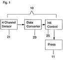
- FIG. 1 there is shown a control system generally designated 10 for a printing press 11 of the present invention.
- the control system 10 has a 4 channel sensor 21, a data converter 23 for processing information from the sensor 21, and a device 25 for controlling ink for the press 11.
- the 4 channel sensor 21 detects the energy reflected from a paper surface, such as the paper web for the press 11, in both the visible region and the infrared region of the electromagnetic spectrum.
- electromagnetic waves in the infrared region have a longer wave length than the visible spectrum, with the wave lengths of the electromagnetic waves in the region of visible light being approximately 400 to 700 nanometers (nm), and the wave lengths of the electromagnetic waves in the infrared region, including near infrared, being equal to or greater than 800 nm.
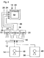
- the control system 10 has a support 12 for placement of a sheet of paper 14 with image or indicia 16 on the sheet 14 in a configuration beneath a pair of opposed lights 18 and 20 for illuminating the sheet 14,
- the system 10 has a first color video camera or sensor 22 having three channels for detecting attributes of the inks from the sheet 14 in the visible region of the electromagnetic spectrum such as red, green and blue, or cyan, magenta, and yellow, and for sending the sensed information over separate lines or leads 24, 26, and 28 to a suitable digital computer 30 or Central Processing unit having a randomly addressable memory (RAM) and a read only memory (ROM), with the computer or CPU 30 having a suitable display 32.
- RAM randomly addressable memory
- ROM read only memory
- the system 10 also has a black/white second video camera or sensor 34 having a filter 50 such that it senses the attributes of the inks in the infrared region of the electromagnetic spectrum, having a wave length greater than the wave length of the electromagnetic waves in the visible region of light.
- the camera or sensor 34 thus senses infrared information from the sheet 14, and transmits the sensed information over a lead 36 to the computer 30, such that the infrared information is stored in and processed by the computer 30.
- the normalized percentage of infrared (IR) reflection vs. the percentage of dot area is show in the chart of FIG. 7. It will be seen that the infrared reflectance of cyan, magenta, and yellow inks show no significant change as a function of percentage of dot area. However, the normalized infrared reflectance of the black ink displays a significant change as a function of percentage of dot area, and changes from a normalized value of 100% IR reflection for 0% dot area to approximately 18% IR reflection corresponding to 100% dot area. Hence, the black ink may be easily sensed and distinguished from other color inks in the infrared region of the electromagnetic waves.
- the sheet 14 may contain a printed image or indicia 16 which is obtained from a current press run of the press 11, termed a production or current copy.
- a sheet 38 containing a printed image or indicia 40, termed a reference copy, from a previous reference press run may be placed on the support 12 beneath the cameras 22 and 34 in order to sense the energy reflected from the sheet 38, and send the sensed information to the memory of the computer 30 for storage and processing in the computer 30, as will be described below.
- the cameras or sensors 22 and 34 may be used to sense both the current copy or sheet 14 and the reference copy or sheet 38.
- the information supplied by the cameras 22 and 34 is formed into digital information by a suitable analog to digital converter in a frame grabber board on the computer 30.
- the computer 30 operates on the digital information which is stored in its memory corresponding to the information sensed from the sheets 14 and 34 by the cameras or sensors 22 and 34.
- FIG. 3 there is shown a block diagram of the control system 10 for the printing press 11 of the present invention.
- the four inks (cyan, magenta, yellow, and black) of the four-color printing press 11 are first preset, after which a print is made by the press 11 with a current ink setting, thus producing a production or current printed copy, as shown.
- the color and black/white video cameras or sensors 22 and 34 of FIG. 2 serve as a four channel sensor 21 to capture an image of the current printed copy, and then place this information into the memory of the computer 30 after it has been formed into digital information.
- an "Ink Separation Process” 23 is used to convert the red, green, blue and IR images captured by the four channel sensor 21 into four separated cyan, magenta, yellow and black ink images, which represent the amount of corresponding ink presented on the live copy.
- the "Ink Separation Precess” 23 may utilize mathematic formulas, data look up tables or other suitable means to perform the data conversion task.
- the similar processes are also applied to the reference copy.
- the four channel sensor 21 is used to capture the red, green, blue and IR images from the reference copy.
- the "Ink Separation Process" 23 is utilized to obtain the cyan, magenta, yellow and black ink images, which represent the amount of corresponding ink presented on the reference copy.
- the ink images of the production copy are compared with the ink images of the reference copy by the computer 30 to detect the variation of ink distribution for each of the cyan, magenta, yellow and black inks.
- the determined differences in ink distribution are then processed by the computer 30 in order to obtain an indication for controlling the keys or other devices of the press 11 in an ink control process, and thus provide an indication of an ink adjustment to the press to obtain further copies which will have a closer match to the reference copy.
- the indication of ink changes may be automatically supplied to the press 11, or the operator may utilize the indications of ink color attributes to set the press 11, such as adjustments to ink input rate by using the keys.
- the four channel sensor 21 is utilized to sense not only attributes in three channels of the visible region, the fourth channel of the sensor 21 senses an attribute in the infrared region in order to determine the correct amount of inks, including black ink, to correctly reproduce the proof.
- the printing press control system uses the four channel detector or sensor 21 to detect the energy reflected from a paper surface, such as the sheets 14 and 38, or the paper web of the press 11, with three channels being in the visible region and one channel being in the infrared region of the electromagnetic spectrum.
- the control system 10 has a device 23 for converting the output of the sensing device 21 to a set of variables which represent the amount of ink presented on the paper for any of the cyan, magenta, yellow, and black inks, and a device 25 responsive to the converting device 23 for adjusting the four-color printing press 11 to maintain the color consistency.
- the bandwidth of the infrared channel may be between 800 nm and 1100 nm, which is a portion of the near infrared region, and which is compatible with a regular silicon detector, although the working wavelength of the infrared channel may be longer than 1100 nm.
- At least three distinct channels are utilized in the visible region which may correspond to red, green, and blue (RGB), or cyan, magenta, and yellow (CMY), or other colors.
- the bandwidth of each channel in the visible region may be less than 70 nm, more than 100 nm, or any value in between, with channels having a multiple peak in its passing band, such as magenta, being also included.
- the sensor device 21 may be constructed from either a single element detector, a one-dimensional (linear) detector, a two-dimensional (area) detector, or other suitable detector structure, as will be seen below.
- the sensor device may be constructed by adding an additional infrared channel to existing devices, adding an infrared channel to a RGB color camera or a densitometer, or by extending the working band into the infrared region, e.g., adding infrared capability to a spectrophotometer.
- the light source 18 and 20 used provides sufficient radiated energy in both the visible region and the infrared region, depending upon the sensor working band and sensitivity.
- All possible values which are output from the sensor device 21 may be used to form a vector space.
- all possible values output from the sensor device 21 with red, green, blue and infrared channels form a four dimensional vector space R-G-B-IR, with the vector space being termed a sensor space S 1 , with each output from the sensor device 21 being termed a vector in the sensor space S 1 , with the minimum number of dimensions required by the sensor structure being 4.
- a set S 1 of elements e 11 and e 12 being given, with the elements e 11 of the set S 1 being the vectors v 11 corresponding to the output from the sensor device 21 of sensing a production or current printed copy, and with the elements e 12 of the set S 1 being the vectors V 12 corresponding to the output from the sensor device 21 sensing a reference printed copy.
- the printed image on a production or current copy may be compared with the printed image on a reference copy in the sensor space, and if the difference between the live copy L.C. s and the reference copy R.C.
- s is within a predefined tolerance level delta, at least for all the channels in the visible region of the sensor space, such that, [ L.C. s - R.C. s ] ⁇ delta, the production or current copy is said to be acceptable by definition.
- a set of variables may be defined to represent the amount of ink presented in a given area.
- a set of variables C, M, Y, and K can be defined to represent or be a function of the amount of cyan, magenta, yellow, and black ink in a given area.
- This set of variables may correspond to the ink volume, average ink film thickness, dot size, or other quantities related to the amount of ink in a given area on the paper surface.
- the vector space formed by this set of variables is termed an ink space S 2 , with the ink space S 2 having a dimension of 4 for a four color printing press 11.
- a set S 2 of elements d 11 and d 12 are given, with the elements d 11 of the set S 2 being the vectors v j1 corresponding to the variables associated with the production or current copy in the ink space S 2 , and with the elements d 12 of the set S 2 being the vectors v j2 corresponding to the variables associated with the reference copy in the ink space s 2 .
- FIG. 9 there exists at least one transfer function or transformation phi which can map the elements d 11 and d 12 of the set S 2 or the four dimensional ink space, into the elements e 11 and e 12 of the set s 1 or the four dimensional sensor space, with the transformation phi being termed a forward transfer function, as shown in FIGS. 9 and 10. It is noted that the subsets in each set S 1 and S 2 may overlap or may be the same.
- the forward transfer function may be used in a soft proof system which can generate a proof image which can be stored in the system as a reference or can be displayed on a CRT screen.
- both the production image and the reference image in the sensor space or set S 1 can be mapped into the ink space or set S 2 by applying the reverse transfer function phi -1 point by point as shown in FIGS. 9 and 10.
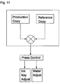
- the difference between the production image and the reference image in the ink space S 2 thus represents the difference of the ink distribution for each of the cyan, magenta, yellow, and black inks, as shown in FIG. 11.
- the difference between the live and reference images in the ink space S 2 indicates which printing unit should be adjusted, which direction, up or down, it should be adjusted, and the amount of ink which should be adjusted.
- a suitable press control formula may be developed to adjust press parameters, such as ink input rate in lithographic or letterpresses, ink consistency in flexographic or gravure presses, water input rate in lithographic presses, or temperature in any of the above, based on the differences between the production and the reference image in the ink space S 2 .
- the press adjustments can be achieved by the automatic control system 10, by press operator alone, or by the interaction between the automatic control system 10 and the press operator.
- the sensor device 21 may be used to monitor the printing web of the press 11 directly, i.e., on press sensing, or to monitor the prints collected from the folder of the press, i.e., off press sensing. If the digital images from the color separation processing, or the film/plate images are available, the image of the reference copy in the sensor device 21 can be generated electronically by the forward transfer function phi. The electronically generated reference may be used to set up the press 11 in order to reduce the make ready time.
- the color reproduction quality can be maintained through the entire press run, through different press runs on different presses, or at different times.
- a closed loop automatic color reproduction control system may be formed without an additional color control target.
- the variation of ink, paper, and other press parameters can be compensated such that the printed copies have the highest possible overall results in matching the reference copy.
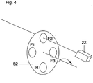
- the camera or sensor 22 may be associated with a rotating filter member 52 having filters which only transmit the desired colors F 1 , F 2 , and F 3 , such as red, green, and blue during rotation, such that the camera or sensor 22 senses and records the colors F 1 , F 2 , and F 3 , sequentially or separately from the printed material which may be taken either from the current press run or from the reference press run.
- the filter member 52 may have an infrared (IR) filter F 4 in order to sense and record the energy reflected form the printed material in the infrared region.
- IR infrared
- the camera or sensor 22 may comprise a charge coupled device (CCD) with built in filters which converts light energy reflected from the printed material into electric energy in a video camera, i.e. F 1 , F 2 , F 3 , and F 4 , (IR), such as the distinct colors red, green, and blue in the visible region, and the near infrared energy in the infrared region, in order to supply the information to the computer 30 for storage and processing, as previously discussed.
- CCD charge coupled device
- IR near infrared energy in the infrared region
- FIG. 6 Another embodiment of the camera or sensor 22 of the present invention is illustrated in FIG. 6, in which like reference numerals designate like parts.
- the camera or sensor 22 has a beam splitter in order to separate the incoming light reflected from the printed material into an infrared beam for a first CCD 1, F 1 such as red for a second CCD 2, F 2 such as green for a third CCD 3, and F 3 such as blue for a fourth CCD.
- suitable prisms, lenses, or mirrors may be utilized to accomplish the beam splitting of light in order to obtain the desired color attributes in the various charge coupled devices to supply the information to the computer 30 for storage and processing in the computer 30, in a manner as previously described.
- any other suitable camera or sensing device may be utilized to obtain the desired colors.
- a control system 10 for a printing press 11 which ascertains three distinct attributes, such as colors, in the visible region of electromagnetic waves and an attribute in the infrared region of the electromagnetic spectrum for the printed inks.
- the control system 10 utilizes these four attributes in a four channel device to indicate and control the ink colors for use in the press 11.
- the colors may be sensed from a sheet taken during a current press run, and from a sheet taken during a reference press run, after which the sensed information is utilized in order to modify ink settings of a press 11 in order to obtain repeatability of the same colors from the reference run to the current press run.
- a consistent quality of colors may be maintained by the printing press 11 irrespective of the number of runs after the reference run has been made, and may be continuously used during a press run if desired.
- a camera based color sensing device for a printing press control system usually comprises of a set of lamp fixtures and a camera assembly. In order to accurately control the printing process, this color sensing device should provide a position-invariant and time-invariant measurement.
- the lens has an uneven light transmittance from the center to the border.
- the amount of light produced by the lamp fixtures varies from time to time.
- the sensitivity of the image sensor may also drift due to temperature variation and aging. Device and calibration procedures are needed to provide a standard viewing condition for this camera based color sensing system.
- a four channel camera assembly 108 is used for capturing images.
- an integrated four channel camera such that shown in Fig. 5 or 6, has not yet become commercially available at the present time.
- the two-camera approach shown in Fig. 2 provides a convenient way to reconstruct this four channel camera 108.
- a color camera is used for capturing red, green and blue images and a monochrome camera for capturing near infrared images.
- Each of these four camera channels normally comprises a Charge Coupled Device (CCD) image sensor.
- CCD Charge Coupled Device
- the working wavelength range of this camera assembly is from 400 nm to about 1000 nm. This is about twice the range of the visible light spectrum.
- the light transmitting characteristics of the lens is wavelength related.
- a special lighting arrangement is often needed to ensure that a standard viewing condition can be established for each of these four camera channels, even if two cameras and two lenses are used. This standard viewing condition is also needed to maintain measurement consistency between two different color sensing systems.
- the preferred light source comprises a first and second groups of lamps 100 and 102, respectively, to provide light in both the visible region (400-700 nm) and the near infrared region (700-1000 nm). At least one of the two groups of lamps 100 or 102 operates only in a single region, either the visible or the near infrared region, but not in both.
- the first group of lamps has an output in both the visible and infrared regions. This covers the entire 400-1000 nm spectrum.
- the second group of lamps 102 has an output in the infrared region (700-1000 nm) only.
- a halogen lamp is rich in energy in the desired 400-1000 nanometer spectrum and can be used in the two lamp groups 100 and 102. Some halogen lamps have filters to reduce the undesirable energy output in wavelengths longer than 1000 nm.
- a lamp MR16 sold by General Electric with a Constant Color Coating is an example of one such lamp.
- energy output can be constrained to the desired spectral region by using optical filters.
- a tempered color temperature compensation filter such as a SCHOTT FG3 filter with a proper thickness is used in front of the first lamp group 100 to provide a standard D50 light source with energy extended into the near infrared region.
- Lamps in the second group 102 can be fitted with a tempered filter, such as a SCHOTT LP78 filter, to block visible light while passing infrared light longer than 780 nm.
- a DC power supply can be used to drive these halogen lamps.
- Xenon lamps can be used, as long as they provide enough energy in both the visible and near infrared regions. It is not necessary that the size of the lamp be small. Lamps with large physical dimensions can also be used. Linear lamps would be an example of the device where light output is present over a large area.
- a calibration target 106 with a uniform light reflectance in the visible and the near infrared region is positioned under a rectangular camera viewing area 104.
- a blank sheet of paper can be used as the calibration target 106 if it remains flat and smooth, and its material content is homogeneous without granularity. Since this type of paper is not prevalent and the quality is difficult to maintain, a special calibration target can be constructed.
- a uniform gray calibration target can be made with various paints and surface modifying agents so as to have a flat spectral curve from 400-1000 nm. The gloss of this target is similar to that of a blank sheet of paper used to print a reference or production copy.
- the calibration target 106 is positioned in the field of view 104 of a four channel camera 108 so that the target surface is near perpendicular to the optical axis of the camera 108.
- the light source is mounted 45 degrees with respect to the camera optical axis to reduce the direct reflection from the target. All remaining surfaces outside the viewing are painted black with a mat finish.
- a display lookup table is created to cause certain pixel values to become more prominent as viewed on a color monitor. This allows the operator to distinguish small changes in camera values so that the lamps can be adjusted to cause the light over that target surface to appear more uniform.
- the first group of lamps 100 is adjusted to minimize the unevenness in the green image. This can be done by pointing the lamps 100 to a different position, readjusting the reflector of the lamps if it exists, or altering the light distribution pattern by using a mesh screen material or neutral density filters. The unevenness is checked in the red and blue images. If the light distribution patterns in the red and blue images are substantially different than that in the green image, the spectral output of the individual lamps and filters should be checked and corrected if necessary. While keeping the first group of lamps 100 unchanged, the second group of lamps 102 is adjusted so that the unevenness of the infrared image is also minimized. Statistics for each image, like standard deviation and average value, can be used to assist this operation.
- Multiple images are captured from the calibration target 106 under this lighting condition.
- the images are averaged to remove individual pixel noise.
- a neighborhood averaging technique may be used to remove any high spatial frequency noise.
- the highest pixel value is found within each averaged image.
- An intermediate image is created by dividing this value by each of the pixel values in the averaged image.
- Each pixel in the intermediate image is then multiplied by a constant gain factor, e.g., 128 for an 8-bit image. This will create a light compensation image for each of the four channels.
- the compensation process can be started by multiplying an image of interest with the light compensation image.
- the result of this multiplication is then divided by the constant gain factor.
- the purpose of this operation is to raise pixel values in the darker areas to a level equal to those in the brightest area.
- the resulting image corresponds to the image of interest as if it had been viewed under a uniform light condition.
- the above compensation goal also can be achieved by lowering the pixel values in the brightest areas to a level equal to those in the darkest areas.
- a gray scale calibration target can be used.
- a gray scale calibration target 110 consists of 12 steps, each with different darkness.
- the darkest and lightest steps should represent the highest density encountered during the printing process and the whitest paper used, respectively.
- the number of steps included in this gray scale is based on the accuracy required. Normally, 10 through 30 steps should be sufficient.
- the material used to make this target should have a flat spectral curve.
- a desired camera value for the lightest step This value should be chosen high enough to provide a wide dynamic range, but be low enough to prevent camera saturation under typical viewing conditions.
- the sensing device has a known relation between the light input and the signal output, such as a linear or a logarithm relation.
- desired camera values for other steps can be calculated accordingly. Representative data showing averaged reflectance and desired camera values of a 12 step target are provided in Table 1.
- iris or camera gains so that the camera value obtained from the lightest step is as close to its desired value as possible. Lock the iris or camera gain settings to prevent any possible changes.
- this camera value related compensation provides a time-invariant viewing condition and greatly improves the system repeatability.
- a standard viewing condition is provided for the camera based color sensing system to provide improved results in the control system of the printing press.
Landscapes
- Engineering & Computer Science (AREA)
- Quality & Reliability (AREA)
- Spectrometry And Color Measurement (AREA)
- Inking, Control Or Cleaning Of Printing Machines (AREA)
Applications Claiming Priority (2)
| Application Number | Priority Date | Filing Date | Title |
|---|---|---|---|
| US493184 | 1995-06-20 | ||
| US08/493,184 US5767980A (en) | 1995-06-20 | 1995-06-20 | Video based color sensing device for a printing press control system |
Publications (2)
| Publication Number | Publication Date |
|---|---|
| EP0749833A2 true EP0749833A2 (de) | 1996-12-27 |
| EP0749833A3 EP0749833A3 (de) | 1997-06-11 |
Family
ID=23959233
Family Applications (1)
| Application Number | Title | Priority Date | Filing Date |
|---|---|---|---|
| EP96109381A Withdrawn EP0749833A3 (de) | 1995-06-20 | 1996-06-12 | Farbsensoranordnung auf Video-Basis für das Regelungssystem einer Druckmaschine und Verfahren zu deren Verwendung |
Country Status (7)
| Country | Link |
|---|---|
| US (1) | US5767980A (de) |
| EP (1) | EP0749833A3 (de) |
| JP (1) | JP4055866B2 (de) |
| KR (1) | KR970000566A (de) |
| CN (1) | CN1104332C (de) |
| AU (1) | AU694345B2 (de) |
| SG (1) | SG48456A1 (de) |
Cited By (10)
| Publication number | Priority date | Publication date | Assignee | Title |
|---|---|---|---|---|
| EP1584471A3 (de) * | 2004-04-09 | 2007-01-24 | Quad/Tech, Inc. | Verfahren und Vorrichtung um einen Druckträger einer Druckmaschine visuell zu inspizieren |
| DE102005037498A1 (de) * | 2005-08-09 | 2007-02-15 | Man Roland Druckmaschinen Ag | Qualitätskontrollsystem für eine Druckmaschine |
| DE102005037497A1 (de) * | 2005-08-09 | 2007-02-15 | Man Roland Druckmaschinen Ag | Kennzeichnungssystem und Qualitäts- und Kennzeichnungsverfahren für eine Bogendruckmaschine |
| DE102007031088A1 (de) * | 2007-07-04 | 2009-01-08 | Manroland Ag | Verfahren zur messtechnischen Erfassung eines bedruckten Bedruckstoffs |
| EP1889721A3 (de) * | 2006-08-16 | 2009-04-08 | manroland AG | Leitstand einer Druckmaschine |
| EP1714786A3 (de) * | 2005-04-22 | 2009-12-16 | Theta System Elektronik GmbH | Vorrichtung zur Inspektion von Druckerzeugnissen |
| WO2017198343A1 (en) * | 2016-05-20 | 2017-11-23 | Bobst Mex Sa | Quality control station with camera calibration system for sheet element processing machine |
| WO2018015193A1 (de) | 2016-07-19 | 2018-01-25 | Koenig & Bauer Ag | Inspektionssystem mit mehreren erfassungsbereichen |
| CN109444155A (zh) * | 2018-12-24 | 2019-03-08 | 劳弗尔视觉科技有限公司 | 一种消除物料阴影的检测装置和方法 |
| EP4306322A1 (de) | 2022-07-12 | 2024-01-17 | Janoschka AG | Verfahren zur prüfung von tiefdruckzylindern und tiefdruckplatten |
Families Citing this family (47)
| Publication number | Priority date | Publication date | Assignee | Title |
|---|---|---|---|---|
| US6748860B2 (en) * | 1994-04-15 | 2004-06-15 | Heidelberger Druckmaschinen Ag | Operating panel for a printing machine, inking control system for a printing machine, and inking control method |
| US6016161A (en) * | 1996-01-25 | 2000-01-18 | Medar, Inc. | Method and system for automatically calibrating a color-based machine vision system |
| US6043909A (en) * | 1996-02-26 | 2000-03-28 | Imagicolor Corporation | System for distributing and controlling color reproduction at multiple sites |
| US7728845B2 (en) * | 1996-02-26 | 2010-06-01 | Rah Color Technologies Llc | Color calibration of color image rendering devices |
| US6459425B1 (en) | 1997-08-25 | 2002-10-01 | Richard A. Holub | System for automatic color calibration |
| IT1284432B1 (it) * | 1996-03-22 | 1998-05-21 | De La Rue Giori Sa | Procedimento di controllo automatico della qualita' di stampa di un'immagine policroma |
| DE19650223A1 (de) * | 1996-12-04 | 1998-06-10 | Heidelberger Druckmasch Ag | Abtastvorrichtung zur bildelementweisen fotoelektrischen Ausmessung eines Messobjekts |
| AT4200U1 (de) * | 1998-12-02 | 2001-03-26 | Oebs Gmbh | Vorrichtung und anlagen zur prüfung winkelabhängiger farben |
| US6185001B1 (en) | 1999-02-01 | 2001-02-06 | The Standard Register Company | Printed document and method of determining the print quality of a printed document |
| FI112549B (fi) * | 1999-03-01 | 2003-12-15 | Honeywell Oy | Menetelmä prosessia tarkkailevilta kameroilta saatavan kuvainformaation synkronoimiseksi |
| JP2001045310A (ja) * | 1999-07-28 | 2001-02-16 | Canon Inc | 画像処理装置、方法および記録媒体 |
| US6376006B1 (en) * | 2000-01-07 | 2002-04-23 | Crown Cork & Seal Technologies Corporation | Closure lining and color detector |
| US6381343B1 (en) | 2000-04-07 | 2002-04-30 | Lotsadots, Inc. | Remote print press proofing system |
| US7102648B1 (en) | 2000-04-11 | 2006-09-05 | Rah Color Technologies Llc | Methods and apparatus for calibrating a color display |
| FR2807705B1 (fr) * | 2000-04-18 | 2002-12-13 | Atel As | Ensemble et procede d'impression sur un substrat plat |
| US6449045B1 (en) * | 2000-05-01 | 2002-09-10 | Xerox Corporation | System and method from reconstruction of spectral curves using measurements for a color sensor and statistical techniques |
| US7391475B2 (en) * | 2002-01-31 | 2008-06-24 | Hewlett-Packard Development Company, L.P. | Display image generation with differential illumination |
| US7280696B2 (en) * | 2002-05-20 | 2007-10-09 | Simmonds Precision Products, Inc. | Video detection/verification system |
| US7032508B2 (en) * | 2003-03-21 | 2006-04-25 | Quad/Tech, Inc. | Printing press |
| US7821675B2 (en) * | 2003-04-04 | 2010-10-26 | Angstrom Technologies, Inc. | Methods and ink compositions for invisibly printed security images having multiple authentication features |
| US20040213436A1 (en) * | 2003-04-25 | 2004-10-28 | Quad/Tech, Inc. | System and method for measuring color on a printing press |
| US8441700B2 (en) | 2003-04-25 | 2013-05-14 | Quad/Tech, Inc. | Image processing of a portion of multiple patches of a colorbar |
| US7627141B2 (en) | 2003-04-25 | 2009-12-01 | Quad/Tech, Inc. | System and method for measuring color on a printing press |
| US7383261B2 (en) * | 2004-01-16 | 2008-06-03 | Xerox Corporation | Reference database and method for determining spectra using measurements from an LED color sensor, and method of generating a reference database |
| JP2005311644A (ja) * | 2004-04-21 | 2005-11-04 | Fuji Xerox Co Ltd | 画像形成装置、校正方法及びそのプログラム |
| US7471385B2 (en) * | 2005-01-13 | 2008-12-30 | Xerox Corporation | Systems and methods for selecting a reference database for determining a spectrum of an object based on fluorescence of the object |
| US8045805B2 (en) * | 2005-03-15 | 2011-10-25 | Applied Visual Sciences, Inc. | Method for determining whether a feature of interest or an anomaly is present in an image |
| US7296518B2 (en) * | 2005-04-19 | 2007-11-20 | Sun Chemical Corporation | Methods for measurement and control of ink concentration and film thickness |
| US7077064B1 (en) | 2005-04-19 | 2006-07-18 | Sun Chemical Corporation | Methods for measurement and control of ink concentration and film thickness |
| US7679782B2 (en) * | 2006-03-09 | 2010-03-16 | Kabushiki Kaisha Toshiba | System and method for extracting grayscale data in accordance with a prescribed tolerance function |
| EP2179331A4 (de) | 2007-08-21 | 2011-11-16 | Angstrom Technologies Inc | System und verfahren für stabile emittierende tonerzusammensetzung |
| DE102007049679B4 (de) * | 2007-10-17 | 2013-10-17 | Robert Bosch Gmbh | Markierungssensor und Verfahren zum Auswerten von Markierungen |
| JP2010056672A (ja) * | 2008-08-26 | 2010-03-11 | Oki Data Corp | 画像処理装置 |
| WO2011009108A2 (en) * | 2009-07-17 | 2011-01-20 | Universal Robotics, Inc. | System and method for automatic calibration of stereo images |
| CN102029780B (zh) * | 2010-09-19 | 2012-04-25 | 中国印刷科学技术研究所 | 印刷色彩稳定性的控制方法及装置 |
| IT1403943B1 (it) * | 2011-02-17 | 2013-11-08 | Nuova Gidue Srl | Procedimento e dispositivo di controllo e gestione dei parametri di stampa di una macchina da stampa, particolarmente con piu' processi di stampa consecutivi. |
| US8780161B2 (en) * | 2011-03-01 | 2014-07-15 | Hewlett-Packard Development Company, L.P. | System and method for modifying images |
| US8605268B2 (en) * | 2011-03-02 | 2013-12-10 | Xerox Corporation | Multi-channel sensor for measuring colorants of prints |
| JP5959001B2 (ja) * | 2012-07-20 | 2016-08-02 | 株式会社小森コーポレーション | シート状物の検査装置 |
| US10574944B2 (en) * | 2013-03-08 | 2020-02-25 | Gelsight, Inc. | Continuous contact-based three-dimensional measurement |
| CN103604754B (zh) * | 2013-10-29 | 2016-03-02 | 杭州电子科技大学 | 一种报纸印刷的文字墨色的测量方法 |
| TWI527427B (zh) * | 2014-04-30 | 2016-03-21 | 虹光精密工業股份有限公司 | 具有影像處理功能的事務機 |
| EP3273854B1 (de) | 2015-03-26 | 2021-09-22 | Universidade de Coimbra | Systeme zur rechnergestützten chirurgie mit von einer frei beweglichen kamera aufgenommenen intraoperativen videos |
| WO2016168307A1 (en) * | 2015-04-13 | 2016-10-20 | Universidade De Coimbra | Methods and systems for camera characterization in terms of response function, color, and vignetting under non-uniform illumination |
| DE102016224307A1 (de) * | 2015-12-15 | 2017-06-22 | Heidelberger Druckmaschinen Ag | Verfahren zur Überprüfung eines Bildinspektionssystems |
| US10796499B2 (en) | 2017-03-14 | 2020-10-06 | Universidade De Coimbra | Systems and methods for 3D registration of curves and surfaces using local differential information |
| WO2021133245A1 (en) * | 2019-12-27 | 2021-07-01 | Viitar Pte. Ltd. | Computer-implemented method and non-transitory computer-readable memory for test result analysis and device for use with method |
Family Cites Families (165)
| Publication number | Priority date | Publication date | Assignee | Title |
|---|---|---|---|---|
| US2968988A (en) * | 1955-03-18 | 1961-01-24 | Crosfield J F Ltd | Apparatus for indicating changes in ink |
| US3376426A (en) * | 1966-11-04 | 1968-04-02 | Hurletron Inc | Color detection apparatus for multiple color printing |
| US3612753A (en) * | 1969-04-23 | 1971-10-12 | Ventures Res & Dev | Self-adaptive system for the reproduction of color |
| US3778541A (en) * | 1971-09-03 | 1973-12-11 | Itek Corp | System for analyzing multicolored scenes |
| US3806633A (en) * | 1972-01-18 | 1974-04-23 | Westinghouse Electric Corp | Multispectral data sensor and display system |
| US3958509A (en) * | 1974-06-13 | 1976-05-25 | Harris Corporation | Image scan and ink control system |
| WO1982000902A1 (en) * | 1980-09-10 | 1982-03-18 | Klie J | Method and circuit for partial correction of the drawing during the colour image reproduction |
| DE2920058C2 (de) * | 1979-05-18 | 1983-09-29 | Dr.-Ing. Rudolf Hell Gmbh, 2300 Kiel | Verfahren und Schaltungsanordnung zur partiellen elektronischen Retusche bei der Farbbildreproduktion |
| US4249217A (en) * | 1979-05-29 | 1981-02-03 | International Business Machines Corporation | Separated sensor array abutment |
| IT1135365B (it) | 1980-02-27 | 1986-08-20 | Roland Man Druckmasch | Procedimento per determinare singoli componenti cromatici in una stampa in plicromia per mezzo d'un densitometro |
| US4308553A (en) * | 1980-03-03 | 1981-12-29 | Xerox Corporation | Method and apparatus for making monochrome facsimiles of color images on color displays |
| US4472736A (en) * | 1980-03-11 | 1984-09-18 | Dainippon Ink And Chemicals Incorporated | Lithographic reproduction original classification and color separation tone curve adjustment |
| DE3024773A1 (de) * | 1980-06-30 | 1982-01-28 | Grapho-Metronic Meß- und Regeltechnik GmbH & Co, KG, 8000 München | Verfahren und einrichtung zur kontrolle und zum steuern der farbgebung einer mehrfarben-druckmaschine |
| JPS57102017A (en) * | 1980-12-17 | 1982-06-24 | Hitachi Ltd | Pattern detector |
| DE3109190C2 (de) * | 1981-03-11 | 1985-07-11 | Dr.-Ing. Rudolf Hell Gmbh, 2300 Kiel | Verfahren zur Reproduktion farbiger Vorlagen im Vierfarbendruck unter Farbrücknahme |
| US4505589A (en) * | 1981-04-03 | 1985-03-19 | Gretag Aktiengesellschaft | Process and apparatus for the colorimetric analysis of printed material |
| GB2115145B (en) * | 1981-07-29 | 1986-05-29 | Dainippon Printing Co Ltd | Method and device for inspecting printed matter |
| US4408231A (en) * | 1981-07-31 | 1983-10-04 | International Business Machines Corporation | Method and apparatus for calibrating a linear array scanning system |
| JPS5846341A (ja) * | 1981-09-16 | 1983-03-17 | Dainippon Screen Mfg Co Ltd | 多色印刷物再現色表示時における再現色変換方法 |
| JPS5848054A (ja) * | 1981-09-17 | 1983-03-19 | Kotobuki Seihan Insatsu Kk | オフセツト印刷用ps版の種類識別方式 |
| DE3309443A1 (de) * | 1982-05-29 | 1983-12-08 | Heidelberger Druckmaschinen Ag, 6900 Heidelberg | Verfahren zur ermittlung der flaechendeckung einer druckvorlage oder druckplatte fuer druckmaschinen |
| US4476487A (en) * | 1982-05-04 | 1984-10-09 | Dr. -Ing. Rudolf Hell Gmbh | Method and circuit arrangement for partial electronic retouch in color image reproduction |
| JPS58201011A (ja) * | 1982-05-19 | 1983-11-22 | Komori Printing Mach Co Ltd | 絵柄信号の判別方法 |
| DE3265413D1 (en) * | 1982-05-29 | 1985-09-19 | Hell Rudolf Dr Ing Gmbh | Method for tone-value-dependent colour removal in four color printing |
| US4481532A (en) * | 1982-06-28 | 1984-11-06 | R. R. Donnelley & Sons Company | Method of determining and storing color printing information |
| US4520504A (en) * | 1982-07-29 | 1985-05-28 | The United States Of America As Represented By The Secretary Of The Air Force | Infrared system with computerized image display |
| EP0106918B1 (de) * | 1982-10-22 | 1986-05-07 | DR.-ING. RUDOLF HELL GmbH | Verfahren und Einrichtung zur Herstellung von Farbauszügen für den Einzelfarbendruck |
| US4794648A (en) * | 1982-10-25 | 1988-12-27 | Canon Kabushiki Kaisha | Mask aligner with a wafer position detecting device |
| JPS5979674A (ja) * | 1982-10-28 | 1984-05-08 | Toshiba Corp | カラ−密着センサ |
| US4631578A (en) * | 1983-03-04 | 1986-12-23 | Canon Kabushiki Kaisha | Method of and apparatus for forming a color picture using a plurality of color correction processings |
| JPS59161976A (ja) * | 1983-03-05 | 1984-09-12 | Canon Inc | カラ−画像処理装置 |
| US4752822A (en) * | 1983-03-08 | 1988-06-21 | Canon Kabushiki Kaisha | Color halftone image processing apparatus producing various screen angles and having an adaptive color image data conversion look-up table and a small-capacity masking memory |
| US5191361A (en) | 1983-03-08 | 1993-03-02 | Canon Kabushiki Kaisha | Image reproducing system |
| JPS59163965A (ja) * | 1983-03-08 | 1984-09-17 | Canon Inc | カラ−システム |
| JPS6031143A (ja) * | 1983-07-29 | 1985-02-16 | Canon Inc | 色再現方式 |
| JPS6041875A (ja) * | 1983-08-17 | 1985-03-05 | Fuji Xerox Co Ltd | カラ−画像読取装置 |
| DE3468650D1 (en) * | 1983-11-04 | 1988-02-18 | Gretag Ag | Method and device for rating the printing quality and/or controlling the ink supply in an offset printing machine, and offset printing machine with such a device |
| ATE30638T1 (de) * | 1983-12-14 | 1987-11-15 | Hell Rudolf Dr Ing Gmbh | Verfahren und einrichtung zur herstellung von farbauszuegen fuer den einzelfarbendruck. |
| JPS60151632A (ja) * | 1984-01-19 | 1985-08-09 | Fuji Photo Film Co Ltd | 写真画像情報の較正方法 |
| US4583186A (en) * | 1984-03-26 | 1986-04-15 | Bremson Data Systems | Computerized video imaging system |
| JPS60224370A (ja) * | 1984-04-23 | 1985-11-08 | Canon Inc | カラ−画像読取り装置 |
| US4839721A (en) * | 1984-08-28 | 1989-06-13 | Polaroid Corporation | Method of and apparatus for transforming color image data on the basis of an isotropic and uniform colorimetric space |
| GB8422209D0 (en) * | 1984-09-03 | 1984-10-10 | Crosfield Electronics Ltd | Image retouching |
| US4678336A (en) * | 1984-09-28 | 1987-07-07 | Komori Printing Machinery Co., Ltd. | Apparatus for detecting image area of thin plate |
| DD227094B5 (de) | 1984-10-04 | 1996-02-22 | Roland Man Druckmasch | Verfahren zur farbmetrischen Auswertung von Druckprodukten |
| JPS61102253A (ja) * | 1984-10-26 | 1986-05-20 | Dainippon Screen Mfg Co Ltd | インキ供給量データファイル作成方法及びインキ供給量データ作成方法 |
| US4731661A (en) * | 1984-11-16 | 1988-03-15 | Sharp Kabushiki Kaisha | Color document reader with white balance adjuster for determining light emission periods for a plurality of different-colored light sources and corresponding integration times for a light sensor by reading a white reference area |
| DE3542884A1 (de) * | 1984-12-04 | 1986-06-05 | Canon K.K., Tokio/Tokyo | Farbbildleser |
| DE3605696A1 (de) * | 1985-02-21 | 1986-08-21 | Fuji Photo Film Co., Ltd., Minami-Ashigara, Kanagawa | Bildausleseverfahren und bildauslesevorrichtung |
| EP0194148A3 (de) * | 1985-03-06 | 1988-05-04 | Lockwood Graders (U.K.) Limited | Verfahren und Vorrichtung zur Erkennung von verfärbten Gebieten und Verfahren und Vorrichtung zum Sortieren von Gegenständen auf diese Weise |
| DE3578768D1 (de) * | 1985-03-14 | 1990-08-23 | Toppan Printing Co Ltd | Einrichtung zum ueberpruefen von abdruecken. |
| DE3613229A1 (de) * | 1985-04-20 | 1986-10-23 | Fuji Photo Film Co., Ltd., Minami-Ashigara, Kanagawa | Verfahren zum erfassen und verarbeiten von bildinformation |
| US4970584A (en) * | 1985-05-15 | 1990-11-13 | Ricoh Company, Ltd. | Method and apparatus for the compensation of color detection |
| US4758885A (en) * | 1985-06-17 | 1988-07-19 | Canon Kabushiki Kaisha | Method of processing color image |
| JPS62101178A (ja) * | 1985-10-29 | 1987-05-11 | Canon Inc | 画像情報処理装置 |
| US5182721A (en) | 1985-12-10 | 1993-01-26 | Heidelberger Druckmaschinen Aktiengesellschaft | Process and apparatus for controlling the inking process in a printing machine |
| US5130935A (en) * | 1986-03-31 | 1992-07-14 | Canon Kabushiki Kaisha | Color image processing apparatus for extracting image data having predetermined color information from among inputted image data and for correcting inputted image data in response to the extracted image data |
| IL78675A (en) | 1986-05-02 | 1993-02-21 | Scitex Corp Ltd | Color separation scanner |
| EP0259981B2 (de) * | 1986-08-13 | 1999-05-06 | Canon Kabushiki Kaisha | Verfahren und Vorrichtung zur Verarbeitung von Farbbildern |
| JPS6361239A (ja) * | 1986-09-01 | 1988-03-17 | Fuji Photo Film Co Ltd | カラ−フイルム検定装置のオフセツトドリフト補正方法 |
| JPS63276676A (ja) * | 1986-09-26 | 1988-11-14 | Olympus Optical Co Ltd | 画像間の対応領域の検出方式 |
| EP0266186B1 (de) * | 1986-10-29 | 1993-09-29 | Canon Kabushiki Kaisha | Farbbildlesegerät oder Farbbilderzeugungsgerät |
| US4839719A (en) * | 1987-01-30 | 1989-06-13 | Minolta Camera Kabushiki Kaisha | Color image reading apparatus with an improved sensor |
| DE3802681C2 (de) * | 1987-01-30 | 1997-01-09 | Fuji Photo Film Co Ltd | Verfahren zur Klassifizierung von Farbvorlagen und Vorrichtung hierfür |
| JPS63191041A (ja) * | 1987-02-03 | 1988-08-08 | Komori Printing Mach Co Ltd | 濃度測定位置合わせ方法 |
| US4947348A (en) * | 1987-03-25 | 1990-08-07 | Kollmorgen Corporation | Densitometer method and system for identifying and analyzing printed targets |
| US4941038A (en) * | 1987-05-11 | 1990-07-10 | The Mead Corporation | Method for color image processing |
| GB2206261B (en) * | 1987-06-22 | 1992-02-05 | Konishiroku Photo Ind | Multicolour image forming method and apparatus |
| WO1989000317A1 (fr) * | 1987-07-06 | 1989-01-12 | Dai Nippon Insatsu Kabushiki Kaisha | Procede et appareil permettant la correction de couleurs |
| FI78025C (fi) * | 1987-08-31 | 1989-06-12 | Valtion Teknillinen | Foerfarande foer kvalitetskontroll av tryckning. |
| EP0310829A3 (de) * | 1987-09-14 | 1990-02-28 | Toppan Printing Co., Ltd. | Vorrichtung zur Simulierung vor dem Ausdrucken |
| JPH0785572B2 (ja) * | 1987-09-22 | 1995-09-13 | 大日本スクリーン製造株式会社 | カラー原画の再現色表示における色成分変換方法 |
| GB8722406D0 (en) * | 1987-09-23 | 1987-10-28 | Crosfield Electronics Ltd | Reproduction of coloured images |
| JP2688055B2 (ja) * | 1987-11-11 | 1997-12-08 | 株式会社リコー | 画像形成装置 |
| US4967379A (en) * | 1987-12-16 | 1990-10-30 | Gretag Aktiengesellschaft | Process for the ink control or regulation of a printing machine by comparing desired color to obtainable color data |
| DE58901780D1 (de) * | 1988-01-14 | 1992-08-13 | Gretag Ag | Verfahren und vorrichtung zur farbregelung einer druckmaschine. |
| JPH01228376A (ja) * | 1988-03-09 | 1989-09-12 | Minolta Camera Co Ltd | 階調表現方法 |
| DE3812099C2 (de) * | 1988-04-12 | 1995-01-26 | Heidelberger Druckmasch Ag | Verfahren zur Farbsteuerung einer Offsetdruckmaschine |
| US5081527A (en) * | 1988-04-12 | 1992-01-14 | Minolta Camera Kabushiki Kaisha | Digital image forming apparatus |
| US4922337B1 (en) * | 1988-04-26 | 1994-05-03 | Picker Int Inc | Time delay and integration of images using a frame transfer ccd sensor |
| US4884130A (en) * | 1988-04-29 | 1989-11-28 | Minnesota Mining And Manufacturing Company | Method of describing a color in a triaxial planar vector color space |
| US4959790A (en) * | 1988-06-28 | 1990-09-25 | F & S Corporation Of Columbus, Georgia | Apparatus and method for producing color corrected reproduction of colored original images |
| JP2728886B2 (ja) * | 1988-07-20 | 1998-03-18 | キヤノン株式会社 | 画像処理装置 |
| JPH0250859A (ja) * | 1988-08-11 | 1990-02-20 | Dainippon Screen Mfg Co Ltd | 色分解条件設定方法および装置 |
| US5101448A (en) * | 1988-08-24 | 1992-03-31 | Hitachi, Ltd. | Method and apparatus for processing a document by utilizing an image |
| US4899214A (en) * | 1988-09-02 | 1990-02-06 | Itek Graphic Corp. | Low cost color scanner |
| US4949172A (en) * | 1988-09-26 | 1990-08-14 | Picker International, Inc. | Dual-mode TDI/raster-scan television camera system |
| US4958221A (en) * | 1988-11-08 | 1990-09-18 | Minolta Camera Kabushiki Kaisha | Digital color copying machine comprising a test mode for making a color adjustment |
| US5121196A (en) * | 1988-11-18 | 1992-06-09 | Konica Corporation | Color processing method and apparatus with a color patch |
| US4977448A (en) * | 1988-12-16 | 1990-12-11 | Matsushita Electric Industrial Co., Ltd. | Color image processing apparatus having exact color reproduction capability |
| DE3903981C2 (de) * | 1989-02-10 | 1998-04-09 | Heidelberger Druckmasch Ag | Verfahren zur Regelung der Farbfüllung bei einer Druckmaschine |
| US5128748A (en) * | 1989-02-15 | 1992-07-07 | Hitachi, Ltd. | Image processing system and apparatus for processing color documents |
| JP2895086B2 (ja) * | 1989-02-28 | 1999-05-24 | コニカ株式会社 | 色推定方法 |
| JPH0695723B2 (ja) | 1989-03-15 | 1994-11-24 | 松下電器産業株式会社 | 色修正装置 |
| US5216498A (en) | 1989-03-22 | 1993-06-01 | Konica Corporation | Image processing apparatus capable of detecting marked region |
| US5029107A (en) * | 1989-03-31 | 1991-07-02 | International Business Corporation | Apparatus and accompanying method for converting a bit mapped monochromatic image to a grey scale image using table look up operations |
| US4910593A (en) * | 1989-04-14 | 1990-03-20 | Entech Engineering, Inc. | System for geological defect detection utilizing composite video-infrared thermography |
| US5107332A (en) * | 1989-05-17 | 1992-04-21 | Hewlett-Packard Company | Method and system for providing closed loop color control between a scanned color image and the output of a color printer |
| US4967264A (en) * | 1989-05-30 | 1990-10-30 | Eastman Kodak Company | Color sequential optical offset image sampling system |
| EP0402079B1 (de) * | 1989-06-06 | 1994-09-14 | Victor Company Of Japan, Ltd. | Druckverfahren für Probe- und Flachdruck unter Nutzung eines elektrophotographischen Aufzeichnungsmittels |
| DE59003421D1 (de) * | 1989-07-14 | 1993-12-16 | Gretag Ag | Verfahren zur Bestimmung der Farbmasszahldifferenzen zwischen zwei mit hilfe einer Druckmaschine gedruckten Rasterfeldern sowie Verfahren zur Farbsteuerung oder Farbregelung des Druckes einer Druckmaschine. |
| DE3924989A1 (de) | 1989-07-28 | 1991-02-07 | Roland Man Druckmasch | Vorrichtung zur durchfuehrung einer umfassenden qualitaetskontrolle an druckbogen |
| US5053866A (en) * | 1989-08-02 | 1991-10-01 | Eastman Kodak Company | Method and an associated apparatus for calibrating a color digital hardcopy device |
| US5166789A (en) | 1989-08-25 | 1992-11-24 | Space Island Products & Services, Inc. | Geographical surveying using cameras in combination with flight computers to obtain images with overlaid geographical coordinates |
| US5045937A (en) * | 1989-08-25 | 1991-09-03 | Space Island Products & Services, Inc. | Geographical surveying using multiple cameras to obtain split-screen images with overlaid geographical coordinates |
| US5282064A (en) | 1989-08-31 | 1994-01-25 | Canon Kabushiki Kaisha | Apparatus for simultaneous reading of reflective and light conductive portions of an original |
| US5302833A (en) | 1989-10-26 | 1994-04-12 | Hamar Laser Instrument, Inc. | Rotational orientation sensor for laser alignment control system |
| US5047842A (en) * | 1989-11-03 | 1991-09-10 | The Trustees Of Princeton University | Color image display with a limited palette size |
| US5003494A (en) * | 1989-12-18 | 1991-03-26 | Eastman Kodak Company | Data storage system for an electronic color printer |
| US5521722A (en) | 1990-01-31 | 1996-05-28 | Thomas De La Rue Limited | Image handling facilitating computer aided design and manufacture of documents |
| US5182571A (en) | 1990-02-26 | 1993-01-26 | Spectra, Inc. | Hot melt ink jet transparency |
| JPH03263993A (ja) | 1990-03-14 | 1991-11-25 | Hitachi Denshi Ltd | レジストレーション検出装置 |
| EP0451106B1 (de) | 1990-04-06 | 1994-06-15 | GRETAG Aktiengesellschaft | Vorrichtung zur Analyse von Druckkontrollfeldern |
| DE4012608A1 (de) | 1990-04-20 | 1991-10-24 | Roland Man Druckmasch | Verfahren und vorrichtung zur bestimmung von passerdifferenzen an druckbildstellen eines mehrfarbenoffsetdruckes |
| US5166755A (en) | 1990-05-23 | 1992-11-24 | Nahum Gat | Spectrometer apparatus |
| US5068912A (en) | 1990-06-04 | 1991-11-26 | Unisys Corp. | Track gauges for aligning and focussing the imaging system in a high speed document handling system |
| DE4023320A1 (de) | 1990-07-21 | 1992-01-23 | Polygraph Contacta Gmbh | Verfahren zur erfassung und steuerung der qualitaet von druckerzeugnissen |
| US5509115A (en) | 1990-08-08 | 1996-04-16 | Peerless Systems Corporation | Method and apparatus for displaying a page with graphics information on a continuous synchronous raster output device |
| US5148288A (en) * | 1990-08-29 | 1992-09-15 | Savitar, Inc. | Standardized color calibration of electronic imagery |
| US5157506A (en) * | 1990-08-29 | 1992-10-20 | Savitar, Inc. | Standardized color calibration of electronic imagery |
| US5181081A (en) | 1990-09-06 | 1993-01-19 | Wea Manufacturing, Inc. | Print scanner |
| US5345320A (en) | 1990-11-29 | 1994-09-06 | Minolta Camera Kabushiki Kaisha | Color image data processing apparatus comprising monochrome pixel detector |
| US5227871A (en) | 1990-11-30 | 1993-07-13 | Canon Kabushiki Kaisha | Image processing apparatus capable of discriminating a predetermined image |
| US5359677A (en) | 1990-12-11 | 1994-10-25 | Sharp Kabushiki Kaisha | Image reader and facsimile machine using such image reader |
| US5272518A (en) | 1990-12-17 | 1993-12-21 | Hewlett-Packard Company | Colorimeter and calibration system |
| US5172224A (en) | 1990-12-18 | 1992-12-15 | Eastman Kodak Company | Printer calibration method using electronically-decoupled color and tone scale adjustments |
| US5175772A (en) | 1991-01-02 | 1992-12-29 | Motorola, Inc. | Automated test for displays using display patterns |
| US5479189A (en) | 1991-02-28 | 1995-12-26 | Chesavage; Jay | 4 channel color display adapter and method for color correction |
| US5295003A (en) | 1991-03-13 | 1994-03-15 | Lee Aldric K | Color conversion system for monochromatic optical scanner |
| JPH04304073A (ja) | 1991-03-30 | 1992-10-27 | Toshiba Corp | 画像処理装置 |
| US5200817A (en) | 1991-08-29 | 1993-04-06 | Xerox Corporation | Conversion of an RGB color scanner into a colorimetric scanner |
| US5216504A (en) | 1991-09-25 | 1993-06-01 | Display Laboratories, Inc. | Automatic precision video monitor alignment system |
| JP3251959B2 (ja) | 1991-10-17 | 2002-01-28 | 株式会社リコー | 画像形成装置 |
| US5317425A (en) | 1992-02-10 | 1994-05-31 | Eastman Kodak Company | Technique for use in conjunction with an imaging system for providing an appearance match between two images and for calibrating the system thereto |
| JP3449744B2 (ja) | 1992-03-05 | 2003-09-22 | ソニー エレクトロニクス インコーポレイテッド | フィルム・ビデオ変換デジタル映像処理方法及び装置 |
| US5363318A (en) | 1992-03-23 | 1994-11-08 | Eastman Kodak Company | Method and apparatus for adaptive color characterization and calibration |
| DE4305693C2 (de) | 1992-04-06 | 1996-12-19 | Hell Ag Linotype | Verfahren zur Farbkalibrierung |
| US5224421A (en) | 1992-04-28 | 1993-07-06 | Heidelberg Harris, Inc. | Method for color adjustment and control in a printing press |
| US5459678A (en) | 1992-07-02 | 1995-10-17 | Feasey; Michael F. | Method and calibration apparatus for calibrating computer monitors used in the printing and textile industries |
| US5404156A (en) | 1992-07-25 | 1995-04-04 | Fuji Xerox Co., Ltd. | Method and apparatus for forming a full-color image |
| US5303028A (en) | 1992-08-24 | 1994-04-12 | Eastman Kodak Company | Spectrometer apparatus for calibrating color imaging apparatus |
| US5282671A (en) | 1992-09-03 | 1994-02-01 | Funk Sonya E | Swing arm chair apparatus |
| US5412577A (en) | 1992-10-28 | 1995-05-02 | Quad/Tech International | Color registration system for a printing press |
| US5404158A (en) | 1992-11-12 | 1995-04-04 | Xerox Corporation | Ink jet printer maintenance system |
| US5357448A (en) | 1993-02-02 | 1994-10-18 | Quad/Tech, Inc. | Method and apparatus for controlling the printing of an image having a plurality of printed colors |
| US5386299A (en) | 1993-03-12 | 1995-01-31 | Ncr Corporation | Method and appartus for automatically calibrating cameras used for document scanning |
| US5329383A (en) | 1993-04-06 | 1994-07-12 | Eastman Kodak Company | Method and apparatus for producing color internegatives with a digital printer |
| US5392360A (en) | 1993-04-28 | 1995-02-21 | International Business Machines Corporation | Method and apparatus for inspection of matched substrate heatsink and hat assemblies |
| US5488492A (en) | 1993-06-04 | 1996-01-30 | Asahi Kogaku Kogyo Kabushiki Kaisha | Apparatus for adjusting color tone of image to be recorded |
| DE4321177A1 (de) | 1993-06-25 | 1995-01-05 | Heidelberger Druckmasch Ag | Vorrichtung zur parallelen Bildinspektion und Farbregelung an einem Druckprodukt |
| GB2282565B (en) | 1993-09-22 | 1996-10-16 | Rockwell International Corp | Device for obtaining registration in a multi-colour printer press |
| JPH07111561A (ja) | 1993-10-12 | 1995-04-25 | Matsushita Electric Ind Co Ltd | 原稿読み取り装置 |
| JPH07115495A (ja) | 1993-10-15 | 1995-05-02 | Matsushita Electric Ind Co Ltd | 原稿読取装置 |
| DE4431270C2 (de) | 1993-10-21 | 1997-01-16 | Roland Man Druckmasch | Verfahren zur Steuerung der Farbführung einer autotypisch arbeitenden Druckmaschine |
| US5416613A (en) | 1993-10-29 | 1995-05-16 | Xerox Corporation | Color printer calibration test pattern |
| US5509086A (en) | 1993-12-23 | 1996-04-16 | International Business Machines Corporation | Automatic cross color elimination |
| US5384621A (en) | 1994-01-04 | 1995-01-24 | Xerox Corporation | Document detection apparatus |
| DE4401534C1 (de) | 1994-01-20 | 1995-03-16 | Heidelberger Druckmasch Ag | Abmusterungseinrichtung zur visuellen Auflichtbeurteilung von flexiblen Vorlagen |
| US5543940A (en) | 1994-02-02 | 1996-08-06 | Electronics For Imaging | Method and apparatus for converting color scanner signals into colorimetric values |
| US5452112A (en) | 1994-03-25 | 1995-09-19 | Eastman Kodak Company | Color image reproduction system field calibration method and apparatus |
| US5528377A (en) | 1994-03-29 | 1996-06-18 | E. I. Du Pont De Nemours And Company | Extended density color printing |
| US5493518A (en) | 1994-04-14 | 1996-02-20 | Cone Mills Corporation | Method and apparatus for simulating colored material |
| US5424553A (en) | 1994-05-16 | 1995-06-13 | Eastman Kodak Company | Method for aligning a lenticular material for printing |
| US5483360A (en) | 1994-06-06 | 1996-01-09 | Xerox Corporation | Color printer calibration with blended look up tables |
| US5491568A (en) | 1994-06-15 | 1996-02-13 | Eastman Kodak Company | Method and apparatus for calibrating a digital color reproduction apparatus |
-
1995
- 1995-06-20 US US08/493,184 patent/US5767980A/en not_active Expired - Lifetime
-
1996
- 1996-05-15 AU AU52272/96A patent/AU694345B2/en not_active Ceased
- 1996-05-16 SG SG1996010027A patent/SG48456A1/en unknown
- 1996-06-12 EP EP96109381A patent/EP0749833A3/de not_active Withdrawn
- 1996-06-14 CN CN96102277A patent/CN1104332C/zh not_active Expired - Fee Related
- 1996-06-20 JP JP16023796A patent/JP4055866B2/ja not_active Expired - Fee Related
- 1996-06-20 KR KR1019960022627A patent/KR970000566A/ko not_active Withdrawn
Cited By (18)
| Publication number | Priority date | Publication date | Assignee | Title |
|---|---|---|---|---|
| EP1584471A3 (de) * | 2004-04-09 | 2007-01-24 | Quad/Tech, Inc. | Verfahren und Vorrichtung um einen Druckträger einer Druckmaschine visuell zu inspizieren |
| EP1714786A3 (de) * | 2005-04-22 | 2009-12-16 | Theta System Elektronik GmbH | Vorrichtung zur Inspektion von Druckerzeugnissen |
| US8237828B2 (en) | 2005-04-22 | 2012-08-07 | Theta System Elektronik Gmbh | Device for inspection of print products |
| DE102005037498A1 (de) * | 2005-08-09 | 2007-02-15 | Man Roland Druckmaschinen Ag | Qualitätskontrollsystem für eine Druckmaschine |
| DE102005037497A1 (de) * | 2005-08-09 | 2007-02-15 | Man Roland Druckmaschinen Ag | Kennzeichnungssystem und Qualitäts- und Kennzeichnungsverfahren für eine Bogendruckmaschine |
| EP1889721A3 (de) * | 2006-08-16 | 2009-04-08 | manroland AG | Leitstand einer Druckmaschine |
| US7876441B2 (en) | 2006-08-16 | 2011-01-25 | Man Roland Druckmaschinen Ag | Control station for a printing press |
| DE102007031088A1 (de) * | 2007-07-04 | 2009-01-08 | Manroland Ag | Verfahren zur messtechnischen Erfassung eines bedruckten Bedruckstoffs |
| WO2017198343A1 (en) * | 2016-05-20 | 2017-11-23 | Bobst Mex Sa | Quality control station with camera calibration system for sheet element processing machine |
| US11117778B2 (en) | 2016-05-20 | 2021-09-14 | Bobst Mex Sa | Quality control station with camera calibration system for sheet element processing machine |
| WO2018015193A1 (de) | 2016-07-19 | 2018-01-25 | Koenig & Bauer Ag | Inspektionssystem mit mehreren erfassungsbereichen |
| DE102016213111A1 (de) | 2016-07-19 | 2018-01-25 | Koenig & Bauer Ag | Inspektionssystem mit mehreren Erfassungsbereichen |
| DE102016213111B4 (de) | 2016-07-19 | 2018-08-09 | Koenig & Bauer Ag | Inspektionssystem mit mehreren Erfassungsbereichen |
| US10525697B2 (en) | 2016-07-19 | 2020-01-07 | Koenig & Bauer Ag | Inspection system having a plurality of detection zones |
| CN109444155A (zh) * | 2018-12-24 | 2019-03-08 | 劳弗尔视觉科技有限公司 | 一种消除物料阴影的检测装置和方法 |
| EP4306322A1 (de) | 2022-07-12 | 2024-01-17 | Janoschka AG | Verfahren zur prüfung von tiefdruckzylindern und tiefdruckplatten |
| DE102023115096A1 (de) | 2022-07-12 | 2024-01-18 | Janoschka AG | Verfahren zur Prüfung von Tiefdruckzylindern und Tiefdruckplatten |
| DE102023115096B4 (de) | 2022-07-12 | 2024-07-25 | Janoschka AG | Verfahren zur Prüfung von Tiefdruckzylindern und Tiefdruckplatten |
Also Published As
| Publication number | Publication date |
|---|---|
| EP0749833A3 (de) | 1997-06-11 |
| AU5227296A (en) | 1997-01-09 |
| KR970000566A (ko) | 1997-01-21 |
| CN1104332C (zh) | 2003-04-02 |
| US5767980A (en) | 1998-06-16 |
| JP4055866B2 (ja) | 2008-03-05 |
| JPH0920003A (ja) | 1997-01-21 |
| AU694345B2 (en) | 1998-07-16 |
| CN1138525A (zh) | 1996-12-25 |
| SG48456A1 (en) | 1998-04-17 |
Similar Documents
| Publication | Publication Date | Title |
|---|---|---|
| US5767980A (en) | Video based color sensing device for a printing press control system | |
| US5903712A (en) | Ink separation device for printing press ink feed control | |
| US5812705A (en) | Device for automatically aligning a production copy image with a reference copy image in a printing press control system | |
| US4884130A (en) | Method of describing a color in a triaxial planar vector color space | |
| US8437041B2 (en) | Print imaging system | |
| US5841955A (en) | Control system for a printing press | |
| US20130250322A1 (en) | Color information processing method, color information processing apparatus, and color information processing system | |
| US5816151A (en) | Device for alignment of images in a control system for a printing press | |
| NZ525412A (en) | Spectral color control method for printing ink supply | |
| US5764386A (en) | Method and system for automatically monitoring the colors of an object at a vision station | |
| US5805280A (en) | Control system for a printing press | |
| JP3011907B2 (ja) | 印刷機制御用の設定値検出方法 | |
| EP0658428B1 (de) | Druckereisteuerungssystem | |
| JP2019128286A (ja) | 印刷物検査方法および印刷物検査装置 | |
| EP0795400A1 (de) | Vorrichtung zum automatischen Ausrichten des Bildes eines Fortdruckexemplars zum Bild eines Referenzexemplars im Kontrollsystem einer Druckpresse | |
| JPH07205410A (ja) | 印刷機用の制御システム | |
| JPH09254456A (ja) | 印刷機制御システム用の画像整合装置 |
Legal Events
| Date | Code | Title | Description |
|---|---|---|---|
| PUAI | Public reference made under article 153(3) epc to a published international application that has entered the european phase |
Free format text: ORIGINAL CODE: 0009012 |
|
| AK | Designated contracting states |
Kind code of ref document: A2 Designated state(s): DE GB |
|
| PUAL | Search report despatched |
Free format text: ORIGINAL CODE: 0009013 |
|
| RAP1 | Party data changed (applicant data changed or rights of an application transferred) |
Owner name: GOSS GRAPHIC SYSTEMS, INC. |
|
| AK | Designated contracting states |
Kind code of ref document: A3 Designated state(s): DE GB |
|
| 17P | Request for examination filed |
Effective date: 19971204 |
|
| 17Q | First examination report despatched |
Effective date: 19990714 |
|
| STAA | Information on the status of an ep patent application or granted ep patent |
Free format text: STATUS: THE APPLICATION IS DEEMED TO BE WITHDRAWN |
|
| 18D | Application deemed to be withdrawn |
Effective date: 20000125 |