EP0749837B1 - Dispositif pour tenir propre les buses d'une tête à jet d'encre - Google Patents
Dispositif pour tenir propre les buses d'une tête à jet d'encre Download PDFInfo
- Publication number
- EP0749837B1 EP0749837B1 EP96250111A EP96250111A EP0749837B1 EP 0749837 B1 EP0749837 B1 EP 0749837B1 EP 96250111 A EP96250111 A EP 96250111A EP 96250111 A EP96250111 A EP 96250111A EP 0749837 B1 EP0749837 B1 EP 0749837B1
- Authority
- EP
- European Patent Office
- Prior art keywords
- ink
- suction
- arrangement according
- printing
- cleaning module
- Prior art date
- Legal status (The legal status is an assumption and is not a legal conclusion. Google has not performed a legal analysis and makes no representation as to the accuracy of the status listed.)
- Expired - Lifetime
Links
Images


Classifications
-
- B—PERFORMING OPERATIONS; TRANSPORTING
- B41—PRINTING; LINING MACHINES; TYPEWRITERS; STAMPS
- B41J—TYPEWRITERS; SELECTIVE PRINTING MECHANISMS, i.e. MECHANISMS PRINTING OTHERWISE THAN FROM A FORME; CORRECTION OF TYPOGRAPHICAL ERRORS
- B41J2/00—Typewriters or selective printing mechanisms characterised by the printing or marking process for which they are designed
- B41J2/005—Typewriters or selective printing mechanisms characterised by the printing or marking process for which they are designed characterised by bringing liquid or particles selectively into contact with a printing material
- B41J2/01—Ink jet
- B41J2/135—Nozzles
- B41J2/165—Prevention or detection of nozzle clogging, e.g. cleaning, capping or moistening for nozzles
- B41J2/16517—Cleaning of print head nozzles
- B41J2/16535—Cleaning of print head nozzles using wiping constructions
- B41J2/16544—Constructions for the positioning of wipers
-
- B—PERFORMING OPERATIONS; TRANSPORTING
- B41—PRINTING; LINING MACHINES; TYPEWRITERS; STAMPS
- B41J—TYPEWRITERS; SELECTIVE PRINTING MECHANISMS, i.e. MECHANISMS PRINTING OTHERWISE THAN FROM A FORME; CORRECTION OF TYPOGRAPHICAL ERRORS
- B41J2/00—Typewriters or selective printing mechanisms characterised by the printing or marking process for which they are designed
- B41J2/005—Typewriters or selective printing mechanisms characterised by the printing or marking process for which they are designed characterised by bringing liquid or particles selectively into contact with a printing material
- B41J2/01—Ink jet
- B41J2/135—Nozzles
- B41J2/165—Prevention or detection of nozzle clogging, e.g. cleaning, capping or moistening for nozzles
- B41J2/16505—Caps, spittoons or covers for cleaning or preventing drying out
- B41J2/16508—Caps, spittoons or covers for cleaning or preventing drying out connected with the printer frame
-
- B—PERFORMING OPERATIONS; TRANSPORTING
- B41—PRINTING; LINING MACHINES; TYPEWRITERS; STAMPS
- B41J—TYPEWRITERS; SELECTIVE PRINTING MECHANISMS, i.e. MECHANISMS PRINTING OTHERWISE THAN FROM A FORME; CORRECTION OF TYPOGRAPHICAL ERRORS
- B41J2/00—Typewriters or selective printing mechanisms characterised by the printing or marking process for which they are designed
- B41J2/005—Typewriters or selective printing mechanisms characterised by the printing or marking process for which they are designed characterised by bringing liquid or particles selectively into contact with a printing material
- B41J2/01—Ink jet
- B41J2/135—Nozzles
- B41J2/165—Prevention or detection of nozzle clogging, e.g. cleaning, capping or moistening for nozzles
- B41J2/16517—Cleaning of print head nozzles
- B41J2/1652—Cleaning of print head nozzles by driving a fluid through the nozzles to the outside thereof, e.g. by applying pressure to the inside or vacuum at the outside of the print head
- B41J2/16523—Waste ink transport from caps or spittoons, e.g. by suction
-
- B—PERFORMING OPERATIONS; TRANSPORTING
- B41—PRINTING; LINING MACHINES; TYPEWRITERS; STAMPS
- B41J—TYPEWRITERS; SELECTIVE PRINTING MECHANISMS, i.e. MECHANISMS PRINTING OTHERWISE THAN FROM A FORME; CORRECTION OF TYPOGRAPHICAL ERRORS
- B41J2/00—Typewriters or selective printing mechanisms characterised by the printing or marking process for which they are designed
- B41J2/005—Typewriters or selective printing mechanisms characterised by the printing or marking process for which they are designed characterised by bringing liquid or particles selectively into contact with a printing material
- B41J2/01—Ink jet
- B41J2/135—Nozzles
- B41J2/165—Prevention or detection of nozzle clogging, e.g. cleaning, capping or moistening for nozzles
- B41J2/16585—Prevention or detection of nozzle clogging, e.g. cleaning, capping or moistening for nozzles for paper-width or non-reciprocating print heads
Definitions
- the invention relates to an arrangement for keeping the nozzles of an ink print head clean, in particular an ink print head with large numbers of nozzles, which is designed in a stacked construction from individual ink print modules.
- Such ink printheads are intended for use in small, fast printers, which in turn are part of modern machines for franking mail or for printing addresses or for product labeling.
- printing is carried out as a single print in one pass through the recording medium. Due to this much larger printing width - approximately one inch - the number of ink nozzles to be arranged one below the other is considerably larger than in the case of ink print heads for office printers.
- EP-A-0 285 155 and EP-A-0 041 706 show an arrangement according to the preamble of claim 1.
- the devices for carrying out these measures are either arranged outside the print area of the ink print head or are arranged on the print head in such a way that the distance from the recording medium is thereby determined.
- a portable, movable ink printhead is required. This generally does not apply to franking machines, since here the mail is moved past the rigidly arranged ink print head.
- the distance to the recording medium is increased so much that the print quality suffers as a result of the greater impact of misalignments, drop speed differences and the given recording medium speed.
- a cover for the nozzles of a vacuum ink printhead which works with fast-drying inks is also known, compare EP 0 173 939 A1.
- the cover is intended on the one hand to prevent the ink from drying out at the nozzle ends during the printing pauses, and on the other hand to ensure that the ink meniscus is neither touched nor pushed back.
- the cover has a circumferential sealing element and a membrane, which form a pressure chamber when the cover is placed on the nozzle surface.
- the inherent tension of the membrane is chosen to be smaller than the surface tension of the ink menisci. In this relatively small pressure chamber, the air quickly becomes saturated with moisture as a result of the ink solvents initially evaporating, so that drying of the nozzles is avoided over shorter printing pauses.
- Another known device for cleaning the nozzle surface of an ink print head has a wiping element which is movably arranged in front of the nozzle surface and, in addition to the ink nozzles, a nozzle from which cleaning fluid is ejected against a deflector orifice and from it is redirected to the nozzle surface.
- the wiping element consists of a belt which contains a plurality of cutouts lying next to one another in the belt direction and which is transported past the nozzle surface in one direction. Depending on the position of the belt, the nozzles are released - cutout - or covered.
- the tape is designed as an endless tape and contained in a tape cassette with a drive.
- the tape lies with one of its cutouts in front of the nozzle openings and releases them for ink ejection.
- cleaning liquid is first discharged dropwise through the cleaning nozzle.
- the belt is then moved so far in its transport direction that, instead of the cutout, the following belt section comes in front of the nozzle surface and covers it.
- the edge of the cutout wipes over the nozzle surface and cleans it of any accumulated dirt.
- the wiping element can be kept sufficiently thin so that the distance from the recording medium is sufficiently small. However, as is evident, this device is only used for rough cleaning of the nozzle surface. A smearing of the nozzle openings when the tape slides past is not excluded, nor is it possible for nozzles to dry out.
- the purpose of the invention is to increase the reliability of ink print heads of the type described in the introduction with little effort.
- the invention has for its object to find a solution with which all the nozzles of an ink print head can be quickly cleaned in the printing breaks and are protected against drying out.
- cleaning should be possible when ink residues are deposited on the nozzle surface and the masses of the cleaning device to be moved should be small.
- the cleaning device should have no influence on the distance between the ink print head and the recording medium and its transport speed.
- the direct arrangement of a cleaning module on the ink print head which can consist of one or more ink printing modules, and the inclusion of the sealing cap in the cleaning process lead to a surprisingly small, compact arrangement with only small moving masses.
- the ink print head is designed with angled nozzle rows, for example in the "non-interlaced design", the anyway free corner space can be used for the cleaning module.
- the interruption of the printing operation for cleaning can be limited to the shortest possible time, since the sealing cap is freed of ink residues in the state pivoted away from the ink print head via the lateral suction channel, so that printing operation is possible here.
- the design of the lever carrying the wiper lip with the two outer lugs ensures that the wiper lip always slides over the nozzle surface with the same placement force.
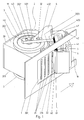
- an ink print head 2 contains three ink print modules 21 and a cleaning module 22 which is lined up parallel to the ink print modules 21.
- the front surface 201 of the inkjet print head 2 protrudes into a recess 10 in a guide plate 1.
- the record carrier (not shown) or the mail item is guided past the guide plate 1 in the direction of the arrow.
- the ink printing modules 21 and the cleaning module 22 are accommodated together in the housing 20 of the ink printing head 2.
- a pin 2021 is formed on the top surface 202 of the housing 20.
- a pin 2031 - not visible here - is formed on the bottom surface 203.
- a gear 3 is rotatably fitted onto each pin 2021, 2031.
- the gear wheel 3 has an outer ring gear 31 and within the latter a driver pin 32.
- a bow-shaped lever 4 with its two legs 40 is attached to both pins 2021, 2031 and to the driver pin 32.
- the lever 4 is provided in the region of its legs 40 with a first slot 401 for the pin 2021 or pin 2031 and with a second slot 402 for the driver pin 32. Both elongated holes 401, 402 are aligned one behind the other.
- a guide strip 2022 is also formed on the top surface 202.
- a guide strip 2032 is formed on the bottom surface 203 - not visible here.
- Both guide strips 2022, 2032 serve to guide the bow-shaped lever 4, which has 40 lugs 403 in the inner region of its legs, which bear non-positively on the outer contour of the guide strips 2022, 2032.
- the pressing force is generated by means of a compression spring 43, which is arranged between the pins 2021 or 2031 and the outer end of the elongated hole 401.
- the bow-shaped lever 4 carries a sealing cap 5 in an articulated manner in the middle of the connecting piece 41 between the legs 40.
- eyes 411 are formed on the connecting piece 41 for receiving an axis 42.
- On the axis 42 a hook-shaped lever and a spring 63 are rotatably arranged.
- the spring 63 is supported on the one hand on the connecting piece 41 and on the other hand on the lever 6, see also FIG. 4.
- the lever 6 carries at its point of rotation opposite end a wiper lip 62 and is provided at the corners of the front edge with lugs 61 which are slightly shorter than the width of the wiper lip 62.
- the lever 6 is pressed by the spring 63 against the front surface 201 such that the lugs 61 on the front surface rest and the wiper lip 62 is bent, see also detail Fig. 3rd Due to the overlying lugs 61, the wiper lip 62 always has the same curvature and thus a constant contact pressure thereof.
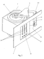
- the ink print head 2 contains three ink print modules 21 and a cleaning module 22, which is arranged transversely under the title print modules 21; otherwise conditions are analogous to those in FIG. 1.
- the sealing cap 5 is removed here. As a result, a universal joint 44 is clearly visible, which is fastened in the connecting piece 41 of the bow-shaped lever 4 and is used for the articulated connection thereof to the sealing cap 5.
- the drive 9 for the gear 3 and thus via the bow-shaped lever 4, the universal joint 44, the coupling to the sealing cap 5 is shown schematically.
- the drive 9 can consist of an actuator with a gear.
- the connection of the ink print head 2 or the cleaning module 22 can be seen via a connecting hose 227 to an external suction pump 7.
- the suction pump 7 is in turn connected via a hose 70 to a suction tank 8, which can be exchangeable.
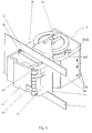
- the first kink 20221 in the guide strip 2022 serves for the defined locking of the nose 403 of the bow-shaped lever 4.
- the sealing cap 5 is pulled by the spring 43 against the front surface 201 in this end position.
- FIG. 4 shows the situation when the sealing cap 5 is pivoted in front of the front surface 201.
- the second kink 20222 in the guide strip 2022 for the other end position can be clearly seen here, as can the suction openings 2230 in the side surface 204 of the housing 20 of the ink print head 2.
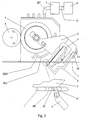
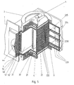
- FIG. 5 the conditions according to FIG. 4 inside the ink print head 2 are disclosed by the angular section.
- Three suction channels 222 run from the front side 220 - see also FIG. 1 - of the Cleaning module 22 to the exit.
- Three further suction channels 223 open on the one hand with the suction openings 2230 in the side surface 204 of the ink print head 2 and on the other hand in a common connecting channel 225 which leads to a suction pump 7 which cannot be recognized.
- the nozzle openings 211 of the ink pressure modules 21 are covered by the sealing cap 5 with the suction pad 52.
- the suction pad 52 is mounted in a seal 51 and this in turn is mounted in a trough 53 which is attached to an end plate 54 in which the universal joint 44 engages.
- the lever 6 with the wiper lip 62 is omitted for reasons of clarity. 6 shows the ink print head 2 with the sealing cap 5 pivoted into the second end position.
- the nose 403 of the lever 4 is in this case latched into the second kink 20222 of the guide strip 2022 and the sealing cap 5 lies against the side surface 204.
- the bow-shaped lever 4 slides with its nose 403 onto the outer contour when moving out of the bevels of the kinks 20221 or 22222 and the sealing cap 5 is lifted off the ink print head 2, consequently avoiding grinding on the surfaces 201 and 204, respectively .
- FIG. 7 shows a cleaning module 22, the suction channels 222 opening on the front are combined by a common connecting channel 224, in which a suction pump in the form of a microstructure pump 226 is integrated. Only a hose 70 to the suction tank 8 is then required on the output side. Analogously, the laterally opening suction channels are combined to form a common connecting channel 225, in which a microstructure pump 226 is also integrated.
- the structure of the sealing cap 5 is illustrated in FIG. 8.
- the suction pad 52 is adapted to the rows of nozzles 211, see also FIG. 2, and is provided with grooves 520 for this purpose, so that direct contact is avoided.
- the suction pad 52 is adapted to the structure of the seal 511, which is provided with chambers 510.
- a chamber 510 is assigned to each ink pressure module 21 and each suction channel opening at the front. From the bottom of each chamber 510, an opening 511 leads through an associated opening 531 into the trough 53 receiving the seal 51 to connecting channels 541.
- the connecting channels 541 are in the End plate 54 is molded in such a way that a connection is established between the part of the sealing cap 5 assigned to the ink ejection area and the part of the sealing cap 5 assigned to the ink suction area.
- the tub 53 and the end plate 54 can be combined into one part.
Landscapes
- Engineering & Computer Science (AREA)
- Environmental & Geological Engineering (AREA)
- Ink Jet (AREA)
Claims (16)
- Arrangement afin de maintenir la propreté des buses d'une tête d'impression à encre comprenant un grand nombre de buses; la tête d'impression à encre se composant d'un module d'impression à encre ou de plusieurs modules d'impression à encre composés en construction à pilage et munie d'un capot étanche (5) arrangé d'une manière ajustable ainsi d'une lèvre essuyante (62),
caractérisé par les caractéristiques suivantes:• à côté du/des module/s d'impression à encre (21), il y a un module de nettoyage (22) qui se trouve à la tête d'impression à encre (2),• le capot étanche (5) est articulé à la tête d'impression à encre (2), cinématiquement accouplé avec la lèvre essuyante (62) et formé de sorte que les surfaces frontales (201, 220) de tous les modules d'impression à encre (21) et du module à nettoyage (22) soient couvrables en même temps. - Arrangement selon la revendication No. 1, caractérisé en ce que le module de nettoyage (22) se succède au/aux module/s d'impression à encre (21).
- Arrangement selon la revendication No. 1, caractérisé en ce que le module de nettoyage (22) est arrangé à travers des modules d'impression à encre (21) et collant à eux.
- Arrangement selon la revendication No. 1, caractérisé en ce que le module de nettoyage (22) est muni au moins d'un seul canal d'aspiration (222) et en ce qu'au côté de sortie il est rattaché au moins à une seule pompe aspirante (7), suivi d'un réservoir d'aspiration (8).
- Arrangement selon la revendication No. 1, caractérisé en ce que le module de nettoyage (22) est muni au moins d'un seul canal d'aspiration (222) et au moins d'une seule pompe à microstructure (226) et en ce qu'au côté de sortie il est rattaché à un réservoir d'aspiration (8).
- Arrangement selon les revendications Nos. 4 à 5, caractérisé en ce qu'au moins un seul canal d'aspiration (222) aboutit à la surface frontale (220) et en ce qu'au mois un seul canal d'aspiration (223) aboutit à une face latérale contiguë (204, 221) à la tête d'impression à encre (2).
- Arrangement selon la revendication No. 6, caractérisé en ce que plusieurs canaux d'aspiration (222, 223) débouchant au même endroit sont ensuite rassemblés à un canal de jonction (224, 225) commun, qui est rattaché à une pompe d'aspiration (7) à son côté de sortie.
- Arrangement selon la revendication No. 6, caractérisé en ce que plusieurs canaux d'aspiration (222, 223) débouchant au même endroit sont ensuite rassemblés à un canal de jonction (224, 225) commun où une pompe à microstructure (226) est intégrée qui est rattachée à un réservoir d'aspiration (8) à son côté de sortie.
- Arrangement selon la revendication No. 6, caractérisé en ce que le nombre des canaux d'aspiration (222, 223) débouchant au même endroit correspond au nombre des modules d'impression à encre (21).
- Arrangement selon la revendication No. 1, caractérisé en ce que le capot étanche (5) est muni d'un bourrage (51) en matériau élastique et d'un coussin d'aspiration (52).
- Arrangement selon les revendications Nos. 9 et 10, caractérisé en ce que le bourrage (51) est réparti en plusieurs chambres (510), dépendant du nombre des canaux d'aspiration (222, 223) et des modules d'impression à encre (21).
- Arrangement selon la revendication No.10, caractérisé en ce qu'au moins un seul canal d'aspiration (541) rattachant la zone d'éjection d'encre à la zone d'aspiration d'encre est façonné dans le capot étanche (5) derrière le coussin d'aspiration (52).
- Arrangement selon la revendication No.10, caractérisé en ce que dans la zone attribuée aux embouchures des buses (211) il y a des rainures (520) façonnées dans le coussin d'aspiration (52).
- Arrangement selon la revendication No.1, caractériséen ce qu'une bande de guidage (2022, 2032) et un tourillon (2021, 2031) sont à la fois façonnés dans la zone de recouvrement (202) et dans la zone de fond (203) de la boîte (20) de la tête d'impression à encre (2),en ce qu'une roue dentée (3) est logée d'une manière pivotante sur chaque tourillon (2021, 2031) et que cette roue dentée est munie d'une couronne dentée extérieure (31) et d'un tenon (32) situé en dedans de la couronne dentée (31),en ce qu'un levier en étrier (4) est d'une part logé d'une manière élastiquement décalable sur les tourillons (2021, 2031, 32) enveloppant la tête d'impression à encre (2), et collé en décalable adhérence aux bandes de guidage (2022, 2032) et qu'il porte d'autre part un joint universel (44), auquel le capot étanche (5) est suspendu, et qu'il est en plus muni d'un arbre (42) sur lequel un levier croché (6) est logé d'une manière élastiquement pivotante, l'autre bout duquel est rattaché à la lèvre essuyante (62) et à la surface frontale et aux bords extérieurs duquel deux taquets (61) sont façonnés qui sont un peu plus courts que la largeur de la lèvre essuyante (62).
- Arrangement selon la revendication No.14, caractériséen ce que les branches (40) du levier en étrier (4) sont munis d'un premier trou oblong (401) pour les tourillons (2021, 2031) et qu'un ressort à pression (43) est arrangé entre le bout extérieur du trou oblong (401) et le tourillon (2021, 2031),en ce que les branches (40) du levier en étrier (4) sont en plus munis d'un deuxième trou oblong (402) pour le tenon (32), le deuxième trou oblong (402) étant aligné avec le premier trou oblong (401) eten ce que des taquets (403) sont façonnés au levier en étrier (4) dans la zone intérieure des branches (40) et collés en adhérence à l'extérieur des bandes de guidage (2023, 2033).
- Arrangement selon les revendications Nos. 14 et 15, caractérisé en ce que chaque bout de la bande de guidage (2023, 2033) est coudé (20221, 20222, 20321, 20322) où le taquet (403) du levier en étrier (4) peut être encliqueté.
Applications Claiming Priority (2)
| Application Number | Priority Date | Filing Date | Title |
|---|---|---|---|
| DE19522594 | 1995-06-19 | ||
| DE19522594A DE19522594C2 (de) | 1995-06-19 | 1995-06-19 | Vorrichtung zur Reinhaltung der Düsen eines Tintendruckkopfes |
Publications (2)
| Publication Number | Publication Date |
|---|---|
| EP0749837A1 EP0749837A1 (fr) | 1996-12-27 |
| EP0749837B1 true EP0749837B1 (fr) | 1997-10-29 |
Family
ID=7764925
Family Applications (1)
| Application Number | Title | Priority Date | Filing Date |
|---|---|---|---|
| EP96250111A Expired - Lifetime EP0749837B1 (fr) | 1995-06-19 | 1996-05-21 | Dispositif pour tenir propre les buses d'une tête à jet d'encre |
Country Status (3)
| Country | Link |
|---|---|
| US (1) | US5883648A (fr) |
| EP (1) | EP0749837B1 (fr) |
| DE (2) | DE19522594C2 (fr) |
Families Citing this family (32)
| Publication number | Priority date | Publication date | Assignee | Title |
|---|---|---|---|---|
| US6015211A (en) * | 1996-06-21 | 2000-01-18 | Brother Kogyo Kabushiki Kaisha | Portable printing device with shutter for covering print head |
| JP2874687B2 (ja) * | 1997-03-27 | 1999-03-24 | 日本電気株式会社 | インクカートリッジおよびインクジェット記録装置 |
| DE19726642C1 (de) * | 1997-06-18 | 1998-09-03 | Francotyp Postalia Gmbh | Vorrichtung zur Positionierung eines Tintendruckkopfes und einer Reinigungs- und Dichtvorrichtung |
| FR2768078B1 (fr) * | 1997-09-10 | 1999-11-26 | Neopost Ind | Station de maintenance pour tete d'impression a jet d'encre de machine a affranchir |
| JP3280308B2 (ja) | 1998-04-23 | 2002-05-13 | ブラザー工業株式会社 | 記録ヘッドおよびその製造方法 |
| GB0113094D0 (en) * | 2001-05-30 | 2001-07-18 | 3M Innovative Properties Co | Inkjet maintenance unit |
| US6659586B2 (en) * | 2001-09-05 | 2003-12-09 | Hewlett-Packard Development Company, L.P. | System and method for servicing non-scanning printhead |
| EP1486333B1 (fr) * | 2002-02-26 | 2010-08-25 | Shima Seiki Mfg., Ltd | Dispositif d'impression |
| US8011299B2 (en) * | 2002-07-01 | 2011-09-06 | Inca Digital Printers Limited | Printing with ink |
| US20040160472A1 (en) * | 2003-02-14 | 2004-08-19 | Najeeb Khalid | Retractable high-speed ink jet print head and maintenance station |
| FR2858581B1 (fr) * | 2003-08-06 | 2005-11-04 | Neopost Ind | Dispositif de nettoyage au vol de buses d'ejection d'encre |
| US20050099451A1 (en) * | 2003-11-04 | 2005-05-12 | Videojet Technologies Inc. | Method and apparatus for reducing debris accumulation in an ink jet printhead |
| EP1604828B1 (fr) * | 2004-06-11 | 2007-03-07 | B.V. Korthofah | Ensemble de tête d'impression comprenant un membre de fermeture mobile |
| EP1827839B1 (fr) * | 2004-12-06 | 2009-02-18 | Silverbrook Research Pty. Ltd | Mecanisme de recouvrement a deux etapes pour imprimantes a jet d'encre |
| US7284820B2 (en) | 2004-12-06 | 2007-10-23 | Silverbrook Research Pty Ltd | Two-stage capping mechanism for inkjet printers |
| US7322669B2 (en) * | 2004-12-06 | 2008-01-29 | Silverbrook Research Pty Ltd | Inkjet printer with protector for a printhead capping facility |
| US7341328B2 (en) | 2004-12-06 | 2008-03-11 | Silverbrook Research Pty Ltd | Inkjet printer with two-stage capping mechanism |
| US7246875B2 (en) | 2004-12-06 | 2007-07-24 | Silverbrook Research Pty Ltd | Protector for a printhead capping facility |
| DE102005052150B4 (de) * | 2005-11-02 | 2007-09-20 | Francotyp-Postalia Gmbh | Vorrichtung zur Reinigung eines Tintendruckkopfes |
| JP2008213219A (ja) * | 2007-03-01 | 2008-09-18 | Canon Inc | インクジェット記録装置 |
| JP5577827B2 (ja) * | 2010-04-28 | 2014-08-27 | ブラザー工業株式会社 | インクジェット記録装置 |
| JP5477981B2 (ja) * | 2012-03-22 | 2014-04-23 | 富士フイルム株式会社 | 液体吐出装置及びメンテナンス方法 |
| JP2013220551A (ja) * | 2012-04-13 | 2013-10-28 | Seiko Epson Corp | 液体噴射装置 |
| GB2532279B (en) * | 2014-11-17 | 2021-03-03 | Postjet Systems Ltd | Printing apparatus |
| JP6818437B2 (ja) | 2016-05-27 | 2021-01-20 | 理想科学工業株式会社 | インクジェット印刷装置 |
| US10744773B2 (en) * | 2017-01-25 | 2020-08-18 | Kyocera Document Solutions Inc. | Recording head recovery system, head cleaning mechanism, and inkjet recording apparatus having the same |
| JP6921662B2 (ja) * | 2017-07-07 | 2021-08-18 | キヤノン株式会社 | インクジェット記録装置 |
| CN107284032A (zh) * | 2017-08-02 | 2017-10-24 | 中国建筑设计院有限公司 | 一种用于全自动数码蓝图打印机的打印喷头保护装置 |
| CN113710495B (zh) * | 2019-04-03 | 2023-05-09 | 株式会社理光 | 液体排出装置和液体排出设备 |
| JP7545632B2 (ja) * | 2020-03-23 | 2024-09-05 | 株式会社リコー | 液体吐出装置 |
| JP7545649B2 (ja) * | 2020-03-23 | 2024-09-05 | 株式会社リコー | 液体吐出装置 |
| KR102798784B1 (ko) * | 2023-05-08 | 2025-04-23 | 주식회사 비전프린팅 | 잔존잉크 제거기능이 구비된 인쇄장치 |
Family Cites Families (14)
| Publication number | Priority date | Publication date | Assignee | Title |
|---|---|---|---|---|
| DE3021913A1 (de) * | 1980-06-11 | 1981-12-17 | Siemens AG, 1000 Berlin und 8000 München | Schwenkbare tintenabweisblende fuer den screibkopf einer tintenschreibeinrichtung |
| US4367479A (en) * | 1980-11-03 | 1983-01-04 | Exxon Research And Engineering Co. | Method and apparatus for purging and/or priming an ink jet |
| US4450454A (en) * | 1980-11-20 | 1984-05-22 | Epson Corporation | Small size ink jet printer |
| US4417259A (en) * | 1981-02-04 | 1983-11-22 | Sanyo Denki Kabushiki Kaisha | Method of preventing ink clogging in ink droplet projecting device, an ink droplet projecting device, and an ink jet printer |
| US4558332A (en) * | 1982-04-02 | 1985-12-10 | Canon Kabushiki Kaisha | Ink jet printer |
| US4684963A (en) * | 1984-06-08 | 1987-08-04 | Seiko Epson Kabushiki Kaisha | Nozzle cover assembly for an ink-on-demand type ink jet printer |
| DE3432620A1 (de) * | 1984-09-05 | 1986-03-13 | Agfa-Gevaert Ag, 5090 Leverkusen | Deckel fuer die duesen eines unterdrucktintendruckkopfes |
| JPS63242643A (ja) * | 1987-03-31 | 1988-10-07 | Canon Inc | 液体噴射記録装置 |
| EP0285155A1 (fr) * | 1987-04-02 | 1988-10-05 | Siemens Aktiengesellschaft | Méthode pour le nettoyage de la zone de projection des tuyères dans les imprimantes par projection d'encre et dispositif pour la mise en oeuvre de la méthode |
| JPH0216056A (ja) * | 1988-07-05 | 1990-01-19 | Canon Inc | インクジェット記録装置 |
| DE3825045A1 (de) * | 1988-07-21 | 1990-01-25 | Siemens Ag | Vorrichtung zum reinigen der duesenflaeche eines tintendruckkopfes |
| DE3825046A1 (de) * | 1988-07-21 | 1990-01-25 | Siemens Ag | Vorrichtung zum abdecken und reinigen der duesenflaeche eines tintendruckkopfes |
| DE4000416C2 (de) * | 1990-01-09 | 1993-12-02 | Siemens Ag | Verfahren und Vorrichtung zur automatischen Betriebssicherstellung einer Tintendruckeinrichtung |
| DE4225799A1 (de) * | 1992-07-31 | 1994-02-03 | Francotyp Postalia Gmbh | Tintenstrahldruckkopf und Verfahren zu seiner Herstellung |
-
1995
- 1995-06-19 DE DE19522594A patent/DE19522594C2/de not_active Expired - Fee Related
-
1996
- 1996-05-21 EP EP96250111A patent/EP0749837B1/fr not_active Expired - Lifetime
- 1996-05-21 DE DE59600038T patent/DE59600038D1/de not_active Expired - Fee Related
- 1996-06-06 US US08/659,299 patent/US5883648A/en not_active Expired - Fee Related
Also Published As
| Publication number | Publication date |
|---|---|
| US5883648A (en) | 1999-03-16 |
| DE19522594C2 (de) | 1999-02-04 |
| DE19522594A1 (de) | 1997-01-02 |
| DE59600038D1 (de) | 1997-12-04 |
| EP0749837A1 (fr) | 1996-12-27 |
Similar Documents
| Publication | Publication Date | Title |
|---|---|---|
| EP0749837B1 (fr) | Dispositif pour tenir propre les buses d'une tête à jet d'encre | |
| EP0749836B1 (fr) | Dispositif pour tenir propre les buses d'une tête à jet d'encre | |
| DE602004005389T2 (de) | Tintenstrahldrucker mit von Tintenabsorbierungskörper versehenem Druckkopfholder | |
| DE69623500T2 (de) | Abdeckeinrichtung eines Tintenstrahldruckkopfes | |
| DE60300063T2 (de) | Tintenstrahlaufzeichnungsgerät | |
| DE69509942T2 (de) | Schutzkappe für einen Tintenstrahlschreiber | |
| DE60316744T2 (de) | Verfahren und Gerät zur Wartung eines Tintenstrahldruckkopfes | |
| DE60035712T2 (de) | Druckknopfabdeckanordnung | |
| DE69810684T2 (de) | Tintenstrahlaufzeichnungsgerät und Tintenabsaugungsverfahren für den Aufzeichnungskopf | |
| DE3889298T2 (de) | Vorrichtung zur Wiederherstellung der Tintenabstrahlfähigkeit bei einem Tintenstrahlaufzeichnungsgerät. | |
| DE69321783T2 (de) | Wischmechanismus für einen Tintenstrahlaufzeichnungskopf und damit versehener Aufzeichnungskopf | |
| DE69404528T2 (de) | Feuchtwischpflegevorrichtung für Farbstrahldrucker ganzer Breite | |
| DE69605409T2 (de) | Reinigungsfluidvorrichtung und verfahren für eine kontinuierlich druckende tintenstrahldüse | |
| DE69027651T2 (de) | Papierzufuhrvorrichtung | |
| DE69723948T2 (de) | Flüssigkeitsausstossgerät und Reinigungsanordnung dafür | |
| DE2607313C3 (de) | Schutz- und Reinigungsvorrichtung für Schreibköpfe in Tintenschreibeinrichtungen | |
| DE102004017801B4 (de) | Wartungsstationsarchitektur und Verfahren für einen Trommeldrucker | |
| DE69502980T2 (de) | Abdeckverfahren für Farbstrahlaufzeichnungsvorrichtung | |
| DE60221473T2 (de) | Schreiberwischverfahren und -anordnung mit Laufband | |
| DE69502654T2 (de) | Modulare Wischeinheit für Tintenstrahldrucker | |
| DE69800782T2 (de) | Tintenstrahldruckkopf mit Tintenzuführkanal | |
| DE60306443T2 (de) | Reinigungsgerät für Tintenstrahldruckkopf | |
| DE10241393A1 (de) | Druckkopfservicestation | |
| DE69832039T2 (de) | Tintenstrahlaufzeichnungskopf und tintenstrahlaufzeichnungsgerät | |
| DE69507730T2 (de) | Feuchtwischer für einen Tintenstrahldruckkopf |
Legal Events
| Date | Code | Title | Description |
|---|---|---|---|
| PUAI | Public reference made under article 153(3) epc to a published international application that has entered the european phase |
Free format text: ORIGINAL CODE: 0009012 |
|
| AK | Designated contracting states |
Kind code of ref document: A1 Designated state(s): CH DE FR GB IT LI |
|
| GRAG | Despatch of communication of intention to grant |
Free format text: ORIGINAL CODE: EPIDOS AGRA |
|
| 17P | Request for examination filed |
Effective date: 19970123 |
|
| 17Q | First examination report despatched |
Effective date: 19970311 |
|
| GRAH | Despatch of communication of intention to grant a patent |
Free format text: ORIGINAL CODE: EPIDOS IGRA |
|
| GRAH | Despatch of communication of intention to grant a patent |
Free format text: ORIGINAL CODE: EPIDOS IGRA |
|
| GRAA | (expected) grant |
Free format text: ORIGINAL CODE: 0009210 |
|
| AK | Designated contracting states |
Kind code of ref document: B1 Designated state(s): CH DE FR GB IT LI |
|
| REG | Reference to a national code |
Ref country code: CH Ref legal event code: NV Representative=s name: ROTTMANN, ZIMMERMANN + PARTNER AG Ref country code: CH Ref legal event code: EP |
|
| GBT | Gb: translation of ep patent filed (gb section 77(6)(a)/1977) |
Effective date: 19971112 |
|
| REF | Corresponds to: |
Ref document number: 59600038 Country of ref document: DE Date of ref document: 19971204 |
|
| ITF | It: translation for a ep patent filed | ||
| ET | Fr: translation filed | ||
| PLBE | No opposition filed within time limit |
Free format text: ORIGINAL CODE: 0009261 |
|
| STAA | Information on the status of an ep patent application or granted ep patent |
Free format text: STATUS: NO OPPOSITION FILED WITHIN TIME LIMIT |
|
| 26N | No opposition filed | ||
| REG | Reference to a national code |
Ref country code: GB Ref legal event code: IF02 |
|
| REG | Reference to a national code |
Ref country code: CH Ref legal event code: PUE Owner name: DIGITAL GRAPHICS INCORPORATION Free format text: FRANCOTYP-POSTALIA AKTIENGESELLSCHAFT & CO.#TRIFTWEG 21-26#16547 BIRKENWERDER (DE) -TRANSFER TO- DIGITAL GRAPHICS INCORPORATION#517, DEOKE-DON YANGJU-SHI#KYUNGGI-DO, 482-050 (KR) |
|
| REG | Reference to a national code |
Ref country code: FR Ref legal event code: TP |
|
| PGFP | Annual fee paid to national office [announced via postgrant information from national office to epo] |
Ref country code: FR Payment date: 20050530 Year of fee payment: 10 |
|
| PGFP | Annual fee paid to national office [announced via postgrant information from national office to epo] |
Ref country code: CH Payment date: 20050531 Year of fee payment: 10 |
|
| REG | Reference to a national code |
Ref country code: GB Ref legal event code: 732E |
|
| PG25 | Lapsed in a contracting state [announced via postgrant information from national office to epo] |
Ref country code: LI Free format text: LAPSE BECAUSE OF NON-PAYMENT OF DUE FEES Effective date: 20060531 Ref country code: CH Free format text: LAPSE BECAUSE OF NON-PAYMENT OF DUE FEES Effective date: 20060531 |
|
| PGFP | Annual fee paid to national office [announced via postgrant information from national office to epo] |
Ref country code: IT Payment date: 20060531 Year of fee payment: 11 Ref country code: GB Payment date: 20060531 Year of fee payment: 11 Ref country code: DE Payment date: 20060531 Year of fee payment: 11 |
|
| REG | Reference to a national code |
Ref country code: CH Ref legal event code: PL |
|
| REG | Reference to a national code |
Ref country code: FR Ref legal event code: ST Effective date: 20070131 |
|
| GBPC | Gb: european patent ceased through non-payment of renewal fee |
Effective date: 20070521 |
|
| PG25 | Lapsed in a contracting state [announced via postgrant information from national office to epo] |
Ref country code: FR Free format text: LAPSE BECAUSE OF NON-PAYMENT OF DUE FEES Effective date: 20060531 Ref country code: DE Free format text: LAPSE BECAUSE OF NON-PAYMENT OF DUE FEES Effective date: 20071201 |
|
| PG25 | Lapsed in a contracting state [announced via postgrant information from national office to epo] |
Ref country code: GB Free format text: LAPSE BECAUSE OF NON-PAYMENT OF DUE FEES Effective date: 20070521 |
|
| PG25 | Lapsed in a contracting state [announced via postgrant information from national office to epo] |
Ref country code: IT Free format text: LAPSE BECAUSE OF NON-PAYMENT OF DUE FEES Effective date: 20070521 |