EP0749855A1 - Radial LKW-Reifen - Google Patents
Radial LKW-Reifen Download PDFInfo
- Publication number
- EP0749855A1 EP0749855A1 EP96304503A EP96304503A EP0749855A1 EP 0749855 A1 EP0749855 A1 EP 0749855A1 EP 96304503 A EP96304503 A EP 96304503A EP 96304503 A EP96304503 A EP 96304503A EP 0749855 A1 EP0749855 A1 EP 0749855A1
- Authority
- EP
- European Patent Office
- Prior art keywords
- bead
- tyre
- carcass
- point
- rim
- Prior art date
- Legal status (The legal status is an assumption and is not a legal conclusion. Google has not performed a legal analysis and makes no representation as to the accuracy of the status listed.)
- Granted
Links
- 239000011324 bead Substances 0.000 claims abstract description 160
- 229920001971 elastomer Polymers 0.000 claims description 44
- 239000005060 rubber Substances 0.000 claims description 44
- 230000003247 decreasing effect Effects 0.000 description 12
- 230000007423 decrease Effects 0.000 description 11
- 230000020169 heat generation Effects 0.000 description 8
- 241000254043 Melolonthinae Species 0.000 description 7
- 230000003014 reinforcing effect Effects 0.000 description 7
- 238000000926 separation method Methods 0.000 description 6
- 229910000831 Steel Inorganic materials 0.000 description 5
- 238000012856 packing Methods 0.000 description 5
- 239000010959 steel Substances 0.000 description 5
- 230000002829 reductive effect Effects 0.000 description 4
- 238000005452 bending Methods 0.000 description 2
- 239000000945 filler Substances 0.000 description 2
- 238000004519 manufacturing process Methods 0.000 description 2
- 230000007935 neutral effect Effects 0.000 description 2
- 229920001875 Ebonite Polymers 0.000 description 1
- 239000004677 Nylon Substances 0.000 description 1
- 229920000297 Rayon Polymers 0.000 description 1
- 238000013459 approach Methods 0.000 description 1
- 239000004760 aramid Substances 0.000 description 1
- 229920003235 aromatic polyamide Polymers 0.000 description 1
- 230000004323 axial length Effects 0.000 description 1
- 150000001875 compounds Chemical class 0.000 description 1
- 239000012141 concentrate Substances 0.000 description 1
- 230000008094 contradictory effect Effects 0.000 description 1
- 238000010586 diagram Methods 0.000 description 1
- 230000000694 effects Effects 0.000 description 1
- 239000000835 fiber Substances 0.000 description 1
- 238000007689 inspection Methods 0.000 description 1
- 230000000670 limiting effect Effects 0.000 description 1
- 229920001778 nylon Polymers 0.000 description 1
- 230000036961 partial effect Effects 0.000 description 1
- 229920000728 polyester Polymers 0.000 description 1
- 239000002964 rayon Substances 0.000 description 1
- 230000000717 retained effect Effects 0.000 description 1
- 230000008961 swelling Effects 0.000 description 1
Images


Classifications
-
- B—PERFORMING OPERATIONS; TRANSPORTING
- B60—VEHICLES IN GENERAL
- B60C—VEHICLE TYRES; TYRE INFLATION; TYRE CHANGING; CONNECTING VALVES TO INFLATABLE ELASTIC BODIES IN GENERAL; DEVICES OR ARRANGEMENTS RELATED TO TYRES
- B60C15/00—Tyre beads, e.g. ply turn-up or overlap
- B60C15/02—Seating or securing beads on rims
-
- B—PERFORMING OPERATIONS; TRANSPORTING
- B60—VEHICLES IN GENERAL
- B60C—VEHICLE TYRES; TYRE INFLATION; TYRE CHANGING; CONNECTING VALVES TO INFLATABLE ELASTIC BODIES IN GENERAL; DEVICES OR ARRANGEMENTS RELATED TO TYRES
- B60C15/00—Tyre beads, e.g. ply turn-up or overlap
-
- B—PERFORMING OPERATIONS; TRANSPORTING
- B60—VEHICLES IN GENERAL
- B60C—VEHICLE TYRES; TYRE INFLATION; TYRE CHANGING; CONNECTING VALVES TO INFLATABLE ELASTIC BODIES IN GENERAL; DEVICES OR ARRANGEMENTS RELATED TO TYRES
- B60C15/00—Tyre beads, e.g. ply turn-up or overlap
- B60C15/02—Seating or securing beads on rims
- B60C15/024—Bead contour, e.g. lips, grooves, or ribs
-
- B—PERFORMING OPERATIONS; TRANSPORTING
- B60—VEHICLES IN GENERAL
- B60C—VEHICLE TYRES; TYRE INFLATION; TYRE CHANGING; CONNECTING VALVES TO INFLATABLE ELASTIC BODIES IN GENERAL; DEVICES OR ARRANGEMENTS RELATED TO TYRES
- B60C3/00—Tyres characterised by the transverse section
- B60C3/04—Tyres characterised by the transverse section characterised by the relative dimensions of the section, e.g. low profile
-
- B—PERFORMING OPERATIONS; TRANSPORTING
- B60—VEHICLES IN GENERAL
- B60C—VEHICLE TYRES; TYRE INFLATION; TYRE CHANGING; CONNECTING VALVES TO INFLATABLE ELASTIC BODIES IN GENERAL; DEVICES OR ARRANGEMENTS RELATED TO TYRES
- B60C9/00—Reinforcements or ply arrangement of pneumatic tyres
- B60C9/02—Carcasses
- B60C9/0292—Carcass ply curvature
-
- Y—GENERAL TAGGING OF NEW TECHNOLOGICAL DEVELOPMENTS; GENERAL TAGGING OF CROSS-SECTIONAL TECHNOLOGIES SPANNING OVER SEVERAL SECTIONS OF THE IPC; TECHNICAL SUBJECTS COVERED BY FORMER USPC CROSS-REFERENCE ART COLLECTIONS [XRACs] AND DIGESTS
- Y10—TECHNICAL SUBJECTS COVERED BY FORMER USPC
- Y10T—TECHNICAL SUBJECTS COVERED BY FORMER US CLASSIFICATION
- Y10T152/00—Resilient tires and wheels
- Y10T152/10—Tires, resilient
- Y10T152/10495—Pneumatic tire or inner tube
- Y10T152/10819—Characterized by the structure of the bead portion of the tire
-
- Y—GENERAL TAGGING OF NEW TECHNOLOGICAL DEVELOPMENTS; GENERAL TAGGING OF CROSS-SECTIONAL TECHNOLOGIES SPANNING OVER SEVERAL SECTIONS OF THE IPC; TECHNICAL SUBJECTS COVERED BY FORMER USPC CROSS-REFERENCE ART COLLECTIONS [XRACs] AND DIGESTS
- Y10—TECHNICAL SUBJECTS COVERED BY FORMER USPC
- Y10T—TECHNICAL SUBJECTS COVERED BY FORMER US CLASSIFICATION
- Y10T152/00—Resilient tires and wheels
- Y10T152/10—Tires, resilient
- Y10T152/10495—Pneumatic tire or inner tube
- Y10T152/10819—Characterized by the structure of the bead portion of the tire
- Y10T152/10837—Bead characterized by the radial extent of apex, flipper or chafer into tire sidewall
-
- Y—GENERAL TAGGING OF NEW TECHNOLOGICAL DEVELOPMENTS; GENERAL TAGGING OF CROSS-SECTIONAL TECHNOLOGIES SPANNING OVER SEVERAL SECTIONS OF THE IPC; TECHNICAL SUBJECTS COVERED BY FORMER USPC CROSS-REFERENCE ART COLLECTIONS [XRACs] AND DIGESTS
- Y10—TECHNICAL SUBJECTS COVERED BY FORMER USPC
- Y10T—TECHNICAL SUBJECTS COVERED BY FORMER US CLASSIFICATION
- Y10T152/00—Resilient tires and wheels
- Y10T152/10—Tires, resilient
- Y10T152/10495—Pneumatic tire or inner tube
- Y10T152/10819—Characterized by the structure of the bead portion of the tire
- Y10T152/10846—Bead characterized by the chemical composition and or physical properties of elastomers or the like
-
- Y—GENERAL TAGGING OF NEW TECHNOLOGICAL DEVELOPMENTS; GENERAL TAGGING OF CROSS-SECTIONAL TECHNOLOGIES SPANNING OVER SEVERAL SECTIONS OF THE IPC; TECHNICAL SUBJECTS COVERED BY FORMER USPC CROSS-REFERENCE ART COLLECTIONS [XRACs] AND DIGESTS
- Y10—TECHNICAL SUBJECTS COVERED BY FORMER USPC
- Y10T—TECHNICAL SUBJECTS COVERED BY FORMER US CLASSIFICATION
- Y10T152/00—Resilient tires and wheels
- Y10T152/10—Tires, resilient
- Y10T152/10495—Pneumatic tire or inner tube
- Y10T152/10855—Characterized by the carcass, carcass material, or physical arrangement of the carcass materials
Definitions
- the present invention relates to a pneumatic tyre, more particularly a heavy duty radial tyre for use mounted on a 15 degree drop centre rim, which has an improved bead structure.
- heavy duty radial tyres such as truck/bus tyres are mounted on a tapered rim such as a 15 degree drop centre rim located and retained thereon by tyre inner pressure, such that the bead bottom of the tyre tightly fits on to the bead seat of the rim and a large engaging force is then obtained.
- heavy duty radial tyres are usually used under a heavy load condition such that the tyre deflects more than 15%. Accordingly, in comparison with the tyres in other fields such as passenger tyres, a particularly high structural durability is required for the bead portions.
- reinforcing layers called bead fillers and the like are disposed. Also to increase bead rigidity, a hard rubber compound is used. Therefore, the bead portions are very resistant to bending deformation.
- an object of the present invention to provide a heavy duty radial tyre, which is improved in the bead seating, rim mounting operation so as to prevent the bead portions from rim chafing and also improved in resistance to a ply edge looseness failure to increase the bead durability.
- the present inventors discovered that the above-mentioned contradictory problems can be solved by specifically limiting the position and size of the bead core disposed in the tyre bead portions, and the present invention resulted.
- a heavy duty radial tyre to be mounted on a 15 degree drop centre rim comprises a tread portion, a pair of sidewall portions, a pair of bead portions with a bead core therein, a carcass comprising a main portion extending between the bead portions and a pair of turnup portions turned up around the bead cores from the axially inside to the outside of the tyre, and a belt disposed radially outside the carcass and inside the tread portion, wherein in a mounted state when the tyre is mounted on a standard rim and inflated to an air pressure of 0.5 ksc, but not loaded, the inside diameter BC the bead cores at the radially innermost point thereof is not more than the diameter BT at the bead heel point.
- the bead heel point is the intersecting point between the bottom line and axially outer surface line of the bead portion.
- the bead core comes close to the bead seat of the rim, and movement of the carcass and rubber around the bead core under heavy load conditions is decreased, and thus bead deformation is also decreased. Therefore, danger of ply looseness is avoided, and the bead portion is greatly improved in durability. Accordingly, the conventional bead reinforcing layer can be removed, and the tyre weight can be reduced.
- the difference between the diameters BC and BT is at least 2 mm, whereby the bead deformation is more effectively reduced, and the bead toe can be prevented from being lifted up.
- the minimum distance between the carcass and bead seat is at least 1.5 mm in order to prevent the carcass cords from being exposed.
- the bead bottom is inclined or tapered towards the axial inside at an inclination angle ⁇ of from 1.0 to 1.9 times the inclined angle ⁇ of the tapered bead seat of the rim.
- the angle ⁇ is less than 1.0 times the angle ⁇ , the rim engaging force can not be effectively increased, and the resistance to rim chafing is decreased.
- angle ⁇ is more than 1.9 times the angle ⁇ , it becomes necessary to greatly compress the bead bottom part when the tyre is mounted on a rim.
- the cross section of the bead core may have a side adjacent to the bead seat which is substantially parallel to the bead seat.
- the bead core has a radially inner surface tapered at substantially same angle as the bead seat.
- the axial distance BP of the axially inner end of this tapered inner surface from the heel point is set in the range of from 1.3 to 2.1 times the maximum width BW of the bead core measured in the direction parallel to the bead seat.
- the inclination of the carcass in the bead portion is optimised, and the thickness of the bead portion is decreased to lessen the heat generation. If the distance BP is less than 1.3 times the width BW, the bead toe is liable to be lifted under an extremely heavy load condition. If more than 2.1 times, it becomes difficult to reduce deformation of the bead portion.
- a straight line drawn to pass through a point P2 at which the carcass main portion starts to contact the bead core and a point P3 at which the carcass main portion and a radially extending straight line passing the axially inner end of the radially inner surface of the bead core intersect each other is inclined at angle ⁇ of from 45 to 60 degrees with respect to the tyre axial direction.
- the angle ⁇ is less than 45 degrees, the bead core excessively shifts towards the axially inner side, and as a result, the rubber thickness of the bead portion axially outside of the bead core is excessively increased to increase the heat generation in the region. If more than 60 degrees, the rubber thickness is excessively increased axially inside the bead core, thus it is not preferable.
- the carcass main portion is substantially straight.
- the carcass cord path is minimised, and the carcass line closely resembles that in the loaded state, and the axially outward swelling of the carcass when loaded is gone.
- the deformation of the bead portion is greatly reduced.
- the bead apex rubber volume is further decreased and the compressive stress in the turnup portion can be greatly decreased because the turnup portion approaches the stress neutral line. Furthermore, as the bead deformation decreases, it becomes possible to eliminate the conventionally used bead reinforcing layers. Therefore, the volume of the bead portion can be greatly decreased to decrease heat generation, and the bead durability is further improved.
- Fig.1 shows a heavy duty radial tyre 1 according to the present invention in its mounted state X where the tyre is mounted on a standard rim, that is, a 15 degree drop centre rim J and inflated to a profiling inner pressure of 0.5 ksc.
- the radial tyre 1 has a pair of axially spaced bead portions 2 with a bead core 6 therein, a pair of sidewall portions 3 each extending radially outwardly from each of the bead portions 2, and a tread portion 4 extending between the radially outer ends of the sidewall portions 3.
- the tyre 1 comprises a carcass 5 having a main portion 5A extending between the bead portions 2 through the tread portion 4 and sidewall portions 3 and a pair of turnup portions 5B turned up around the bead cores 6 from the axially inside to outside of the tyre, a belt 7 disposed radially outside the carcass 5 and inside the tread portion 4, a tread rubber disposed radially outside the belt 7 defining the tread portion, and a pair of sidewall rubbers 17 disposed axially outside the carcass defining the axially outer surface of the sidewall portions 3.
- the belt 7 in this embodiment comprises four plies of steel cords disposed to cross each other.
- the steel cords of the radially innermost ply 7A are laid at an angle of from 50 to 70 degrees with respect to the tyre equator C
- the steel cords of each of the three outer plies 7B, 7C, 7D are laid at an angle of not more than 30 degrees with respect to the tyre equator C.
- Fig.2 shows the bead portion 2 in the demounted state Y in which the tyre 1 is not mounted on a rim.
- the bead portion 2 has a bead bottom 10 tapered towards the axial inside of the tyre.
- the taper angle ⁇ with respect to an axial line L is set in the range of from 1.0 to 1.9 times, preferably 1.2 to 1.9 times the taper angle ⁇ of the tapered bead seat J1 of the rim J.
- the bead core 6 has a hexagonal sectional shape to withstand a heavy load, and one side 11 thereof is substantially parallel with the bead seat J1 in the mounted state X. That is, as the bead core 6 is a ring body, it has an axially inwardly tapered face 11 corresponding to the side 11.
- the axial length BP measured from the axially inner edge 11A of the tapered face 11 to the bead heel point 13 is set in the range of from 1.3 to 2.1 times the width BW of the bead core 6 measured parallel with the bead seat J1.
- the bead heel point 13 is defined as the intersection between the extension line of the axial outer surface 12 and the extension line of the bead bottom 10.
- the axial outer surface 12 of the bead portion 2 contacts the axially inner surface of the rim flange J2.
- the inside diameter BC of the bead core 6 at the radially innermost point 6a thereof is not more than the inside diameter BT at the heel point 13, more preferably not more than the inside diameter BT minus 2 mm.
- the carcass 5 comprises at least one ply of rubberised cords arranged radially at an angle of from 90 to 70 degrees with respect to the tyre equator C to have a radial or semiradial radial ply structure.
- organic fibre cords e.g. polyester, aromatic polyamide, nylon, rayon and the like or steel cords can be used.
- the carcass 5 in this embodiment consists of one ply 5a of steel cords arranged at 90 degrees with respect to the tyre equator C.
- a bead apex rubber 9 extending and tapering radially outwardly from the bead core 6 is disposed.
- the main portion 5A of the carcass 5 substantially directly abuts the axially inner surface of the bead apex rubber 9.
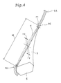
- the carcass line of the main portion 5A that is, the carcass centre line of the main portion 5A is substantially straight in the region K between the above-mentioned lower point P2 and an upper point P1 at which the main portion 5A contacts with the radially outer edge 9E of the bead apex rubber 9.
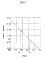
- substantially straight carcass line means that its maximum deviation V from the straight line N (of which length is M) drawn from the upper point P1 to the lower point P2, measured normally to the straight line N, is not more than 0.02 times the length M. In conventional tyres, the deviation V is at least 0.055 times the length M and the carcass line is curved, not straight.
- the carcass line is substantially straight in the above-mentioned region K, the carcass is prevented from protruding outwardly when the tyre is loaded, and deformation of the bead portion 2 is decreased. Further, the thickness of the bead apex rubber 9 is lessened, and the carcass turnup portion 5B comes close to the neutral stress line. As a result, the compressive stress acting on the turnup portions 5B is greatly decreased. In this invention, therefore, it becomes possible to eliminate conventional bead reinforcing cord layers disposed around the bead cores and/or axially inside and outside the carcass s turnup portions.
- the contact pressure between the bead portion 2 and rim flange is excessively increased when a tyre load of more than 3 times the standard load and the like is applied, and the durability of the bead portion 2 greatly decreases.
- the deviation V is under -0.02M (axially outward)
- the carcass cord tension decreases, the carcass cords are waved or undulated in the tread crown part and the buttress part 15, which has a bad effect on the tyre profile when the tyre is normally inflated and decreases the uneven wear resistance.
- a cushion rubber (shown in Fig.2) having a thickness T of not less than 1.6 mm and a hardness different from the bead apex rubber 9 is disposed, thereby preventing ply separation due to the sharing force caused by the tyre deflection during running.
- the carcass line in the tread portion 4 is defined by a single radius of curvature R1 having its centre on the tyre equatorial plane.
- the carcass line radially outside the maximum tyre width points 16 is defined by a single radius of curvature R2 having a centre on a straight line Q drawn to extend between the two maximum tyre width points 16 in the sidewall portions, and the carcass line radially inside the maximum tyre width points 16 is defined by a single radius of curvature R3 having a centre on the above-mentioned axial line Q.
- the radius R1 is larger than the radius R2, and the radius R2 is substantially equal to the radius R3.
- the upper point P1 the curved part of the single radius of curvature R3 and the substantially straight part in the region K are smoothly connected with each other without forming any inflection point.
- Such a stress concentration is avoided by substantially aligning the boundary with the outer edge 9E or the point P1. Thus, it is not necessary to use any of the reinforcing layer or to increase the rubber volume.
- the turnup portions 5B of the carcass 5 has a concave part substantially directly contacting the axially outside surface of the bead apex rubber 9.
- the carcass line of this concave part has a single radius of curvature R4 whose centre is outside the tyre.
- the radius R4 is smaller than the radius R3.
- the height H9 of the radially outer edge 9E of the bead apex rubber is in the range of from 0.1 to 0.3 times the height Hk of the radially outer surface of the carcass 5 at the tyre equator, each from the bead base line L0 passing the two heel points 13. If the bead apex height H9 is less than 0.1 Hk, the carcass 5 is bent abruptly near the bead apex rubber 9, which is liable to cause air-retention problems in manufacturing the tyre and carcass cord cutting during running. If the bead apex height H9 is more than 0.3 Hk, heat generation increases to deteriorate the bead durability, and the tyre weight is increased.
- the height H9 is preferably not more than 0.25 Hk, more preferably not more than 0.20 Hk.
- the radius of curvature R3 is preferably in the range of 0.75 to 1.15 times the carcass height Hk. If R3 is less than 0.75 Hk, the volume of the bead portion 2 increases to increase the tyre weight, and also the heat generation during running increases to decrease the durability. If R3 is more than 1.15 Hk, the manufacturing of the tyre becomes difficult.
- the bead portion 2 is provided with a radially extending side packing rubber 19 and a chafer rubber 20.
- the side packing rubber 19 is disposed between the turnup portion 5B of the carcass 5 and a radially inner part of the sidewall rubber 17.
- the chafer rubber 20 extends from the axially inside to outside of the bead core and covers the axially outside of the tapered radially inner edge part of the side packing rubber 19.
- the axially outer part of the chafer rubber 20 is overlap-jointed with the tapered radially inner edge part of the sidewall rubber 17 as shown in Fig.2.
- the chafer rubber 20 defines the bottom surface 10 and the axial outer surface 12 of the bead portion.
- the bead apex height H9, the height H5 of the axially outer edge of the turnup portion 5B, and the height H20 of the radially outer edge of the chafer rubber 20, each from the bead base line L0, are H20 ⁇ H9 ⁇ H5.
- the 100% modulus MS of the sidewall rubber 17 is 10 to 20 kgf/cm 2 .
- the 100% modulus MP of the side packing rubber 19 is 14 to 47 kgf/cm 2 .
- the 100% modulus MA of the bead apex rubber 9 is 14 to 84 kgf/cm 2 .
- the 100% modulus MC of the chafer rubber 20 is 55 to 71 kgf/cm 2 .
- the 100% modulus MT of the topping rubber for the carcass 5 is 37 to 47 kgf/cm 2 .
- the bead rigidity is optimised to effectively spread stress in the bead portion 2 into a wide range. Therefore, the carcass cords are prevented from being bent around the radially outer edge of the bead apex 9, and their fatigue and separation failure can be avoided.
- the sidewall rubber 17 can be expanded or compressed relatively easily, accompanying bending deformation of the carcass 5.
- the resistance to rim chafing is improved by the high modulus chafer rubber 20.
- separation from the carcass 5 is prevented, and stress transfer to the bead portion 2 can be avoided.
- MA is more than 84 kgf/cm 2
- MP is more than 47 kgf/cm 2
- MS is more than 20 kgf/cm 2
- MC is more than 71 kgf/cm 2
- the bead rigidity becomes excessively high, and the strength of the carcass cords decrease around the radially outer edge of the bead apex 9, and ply looseness occurs.
- MA and MP are less than 14 kgf/cm 2 , MS is less than 10 kgf/cm 2 and MC is less than 55 kgf/cm 2 , the a required minimum rigidity for the bead portion 2 can not be obtained, and thus running performance of the tyre greatly decreases.
- the bead apex rubber 9 and side packing rubber 19 are disposed in the bead portion, these rubber layers are required to have a higher rigidity than the sidewall rubber 17. Therefore, it is more preferable that the 100% modulus MA is not less than 64 kgf/cm 2 , and the 100% modulus MP is not less than 37 kgf/cm 2 .
- the carcass 5 can follow the deformation of the bead portion 2, and ply looseness, separation failure can be prevented.
- the above-mentioned standard rim is a rim officially approved for the tyre by for example JATMA (Japan), TRA (USA), ETRTO (Europe) and the like, and the standard inner pressure and standard load are the maximum air pressure and maximum tyre load for the tyre specified by the same associations.
- Example tyres 1 to 20 produced less heat and were improved in the bead durability and rim mounting and decreased in the tyre weight in comparison with the conventional tyre and reference tyres.
- a heavy duty radial tyre can be improved in the rim mounting and resistance to rim chafing, and the tyre weight can be reduced.
Landscapes
- Engineering & Computer Science (AREA)
- Mechanical Engineering (AREA)
- Tires In General (AREA)
Applications Claiming Priority (9)
| Application Number | Priority Date | Filing Date | Title |
|---|---|---|---|
| JP15168495 | 1995-06-19 | ||
| JP15168495 | 1995-06-19 | ||
| JP151684/95 | 1995-06-19 | ||
| JP16380995 | 1995-06-29 | ||
| JP16380995A JP2724291B2 (ja) | 1995-06-29 | 1995-06-29 | 重荷重用タイヤ |
| JP163809/95 | 1995-06-29 | ||
| JP8066277A JP2781542B2 (ja) | 1995-06-19 | 1996-03-22 | 重荷重用ラジアルタイヤ |
| JP66277/96 | 1996-03-22 | ||
| JP6627796 | 1996-03-22 |
Publications (2)
| Publication Number | Publication Date |
|---|---|
| EP0749855A1 true EP0749855A1 (de) | 1996-12-27 |
| EP0749855B1 EP0749855B1 (de) | 2000-03-08 |
Family
ID=27299077
Family Applications (1)
| Application Number | Title | Priority Date | Filing Date |
|---|---|---|---|
| EP96304503A Expired - Lifetime EP0749855B1 (de) | 1995-06-19 | 1996-06-18 | Radial LKW-Reifen |
Country Status (3)
| Country | Link |
|---|---|
| US (1) | US5772811A (de) |
| EP (1) | EP0749855B1 (de) |
| DE (1) | DE69606922T2 (de) |
Cited By (10)
| Publication number | Priority date | Publication date | Assignee | Title |
|---|---|---|---|---|
| EP0818331A3 (de) * | 1996-07-08 | 1998-12-09 | Bridgestone Corporation | Radiale LKW-Reifen |
| FR2787744A1 (fr) * | 1998-12-24 | 2000-06-30 | Michelin Soc Tech | Bourrelet de pneumatique radial |
| EP0982158A3 (de) * | 1998-08-24 | 2001-06-13 | Bridgestone Corporation | Radiale lkw-luftreifen |
| WO2002030689A1 (en) * | 2000-10-10 | 2002-04-18 | Societe De Technologie Michelin | Tire bead with angled anchoring zone |
| WO2002030687A3 (en) * | 2000-10-10 | 2002-07-25 | Michelin Soc Tech | Tire having a carcass portion in the shape of a truncated cone |
| EP0947358A4 (de) * | 1997-07-01 | 2003-03-19 | Sumitomo Rubber Ind | Radialreifen für schwerfahrzeuge |
| US6736178B2 (en) * | 1998-04-10 | 2004-05-18 | Sumitomo Rubber Industries, Ltd. | Pneumatic tire with specified bead portion |
| EP2403725B1 (de) * | 2009-03-04 | 2013-08-28 | Compagnie Generale Des Etablissements Michelin | Reifen für schwerfahrzeug |
| JP2016002961A (ja) * | 2014-06-19 | 2016-01-12 | 株式会社ブリヂストン | タイヤ |
| EP3828008A1 (de) * | 2019-11-26 | 2021-06-02 | Sumitomo Rubber Industries, Ltd. | Luftreifen |
Families Citing this family (18)
| Publication number | Priority date | Publication date | Assignee | Title |
|---|---|---|---|---|
| JP3158058B2 (ja) * | 1996-05-28 | 2001-04-23 | 住友ゴム工業株式会社 | 重荷重用ラジアルタイヤ |
| EP0997325B1 (de) * | 1998-10-29 | 2003-08-20 | Sumitomo Rubber Industries Ltd. | Reifen |
| JP3431847B2 (ja) * | 1998-12-22 | 2003-07-28 | 住友ゴム工業株式会社 | 空気入りタイヤ |
| JP3325004B2 (ja) * | 1999-10-21 | 2002-09-17 | 住友ゴム工業株式会社 | 空気入りタイヤ |
| JP2001191764A (ja) * | 2000-01-14 | 2001-07-17 | Bridgestone Corp | 空気入りタイヤ |
| US6513561B1 (en) | 2000-01-27 | 2003-02-04 | Bridgestone/Firestone North American Tire, Llc | Pneumatic tire having multiple modulus body cord to reduce rolling resistance |
| US6595256B1 (en) | 2000-09-22 | 2003-07-22 | Bridgestone/Firestone North American Tire, Llc | Pneumatic tire having a body cord insert that reduces the rolling resistance of the tire |
| US20050006017A1 (en) * | 2000-10-10 | 2005-01-13 | Michelin Recherche Et Technique S.A. | Tire having a carcass portion in the shape of a truncated cone |
| WO2002085647A1 (en) * | 2001-04-16 | 2002-10-31 | Sumitomo Rubber Industries, Ltd | Pneumatic tire |
| JP2002337516A (ja) * | 2001-05-21 | 2002-11-27 | Sumitomo Rubber Ind Ltd | 空気入りタイヤ |
| JP4041479B2 (ja) * | 2004-08-06 | 2008-01-30 | 住友ゴム工業株式会社 | 重荷重用タイヤ |
| JP4966687B2 (ja) | 2007-02-15 | 2012-07-04 | 株式会社ブリヂストン | 空気入りタイヤ |
| FR2969038B1 (fr) * | 2010-12-21 | 2012-12-28 | Michelin Soc Tech | Pneumatique dont l'armature de carcasse est renforcee par une couche d'elements de renforcement dans la zone du bourrelet |
| JP5702421B2 (ja) * | 2013-03-28 | 2015-04-15 | 株式会社ブリヂストン | 重荷重用空気入りタイヤ |
| AU2017228601B2 (en) * | 2016-09-25 | 2023-03-23 | The Yokohama Rubber Co., Ltd. | Heavy duty tyre |
| JP7380014B2 (ja) * | 2019-09-26 | 2023-11-15 | 住友ゴム工業株式会社 | 空気入りタイヤ |
| JP7501072B2 (ja) * | 2020-04-21 | 2024-06-18 | 住友ゴム工業株式会社 | 空気入りタイヤ |
| DE102024207563A1 (de) * | 2024-08-08 | 2026-02-12 | Continental Reifen Deutschland Gmbh | Fahrzeugreifen |
Citations (5)
| Publication number | Priority date | Publication date | Assignee | Title |
|---|---|---|---|---|
| GB2187146A (en) * | 1986-02-20 | 1987-09-03 | Bridgestone Corp | Pneumatic radial tire |
| DE4136528A1 (de) * | 1990-11-07 | 1992-05-14 | Sumitomo Rubber Ind | Schlauchloser radialreifen fuer schwerlastbetrieb |
| EP0533425A1 (de) * | 1991-09-17 | 1993-03-24 | Sumitomo Rubber Industries Limited | Radialer Reifen für LKW |
| JPH05185811A (ja) * | 1991-07-16 | 1993-07-27 | Bridgestone Corp | 重荷重用空気入りラジアルタイヤ |
| JPH06312605A (ja) * | 1993-04-30 | 1994-11-08 | Bridgestone Corp | 空気入りラジアルタイヤ |
Family Cites Families (1)
| Publication number | Priority date | Publication date | Assignee | Title |
|---|---|---|---|---|
| JPH05345507A (ja) * | 1992-06-16 | 1993-12-27 | Yokohama Rubber Co Ltd:The | 重荷重用空気入りタイヤ |
-
1996
- 1996-06-13 US US08/662,497 patent/US5772811A/en not_active Expired - Fee Related
- 1996-06-18 EP EP96304503A patent/EP0749855B1/de not_active Expired - Lifetime
- 1996-06-18 DE DE69606922T patent/DE69606922T2/de not_active Expired - Fee Related
Patent Citations (5)
| Publication number | Priority date | Publication date | Assignee | Title |
|---|---|---|---|---|
| GB2187146A (en) * | 1986-02-20 | 1987-09-03 | Bridgestone Corp | Pneumatic radial tire |
| DE4136528A1 (de) * | 1990-11-07 | 1992-05-14 | Sumitomo Rubber Ind | Schlauchloser radialreifen fuer schwerlastbetrieb |
| JPH05185811A (ja) * | 1991-07-16 | 1993-07-27 | Bridgestone Corp | 重荷重用空気入りラジアルタイヤ |
| EP0533425A1 (de) * | 1991-09-17 | 1993-03-24 | Sumitomo Rubber Industries Limited | Radialer Reifen für LKW |
| JPH06312605A (ja) * | 1993-04-30 | 1994-11-08 | Bridgestone Corp | 空気入りラジアルタイヤ |
Non-Patent Citations (2)
| Title |
|---|
| PATENT ABSTRACTS OF JAPAN vol. 017, no. 610 (M - 1508) 10 November 1993 (1993-11-10) * |
| PATENT ABSTRACTS OF JAPAN vol. 94, no. 011 * |
Cited By (16)
| Publication number | Priority date | Publication date | Assignee | Title |
|---|---|---|---|---|
| EP0818331A3 (de) * | 1996-07-08 | 1998-12-09 | Bridgestone Corporation | Radiale LKW-Reifen |
| US5979527A (en) * | 1996-07-08 | 1999-11-09 | Bridgestone Corporation | Heavy duty pneumatic radial tires with at least three bead portion rubbers |
| EP0947358A4 (de) * | 1997-07-01 | 2003-03-19 | Sumitomo Rubber Ind | Radialreifen für schwerfahrzeuge |
| US6736178B2 (en) * | 1998-04-10 | 2004-05-18 | Sumitomo Rubber Industries, Ltd. | Pneumatic tire with specified bead portion |
| US6276417B1 (en) | 1998-08-24 | 2001-08-21 | Bridgestone Corporation | Heavy duty pneumatic radial tires with specified bead core compression ratio |
| EP0982158A3 (de) * | 1998-08-24 | 2001-06-13 | Bridgestone Corporation | Radiale lkw-luftreifen |
| WO2000038938A3 (fr) * | 1998-12-24 | 2002-09-26 | Michelin Soc Tech | Bourrelet de pneumatique radial |
| FR2787744A1 (fr) * | 1998-12-24 | 2000-06-30 | Michelin Soc Tech | Bourrelet de pneumatique radial |
| WO2002030689A1 (en) * | 2000-10-10 | 2002-04-18 | Societe De Technologie Michelin | Tire bead with angled anchoring zone |
| WO2002030687A3 (en) * | 2000-10-10 | 2002-07-25 | Michelin Soc Tech | Tire having a carcass portion in the shape of a truncated cone |
| CN1326714C (zh) * | 2000-10-10 | 2007-07-18 | 米其林技术公司 | 具有截锥形胎体部分的轮胎 |
| EP2403725B1 (de) * | 2009-03-04 | 2013-08-28 | Compagnie Generale Des Etablissements Michelin | Reifen für schwerfahrzeug |
| US9744813B2 (en) | 2009-03-04 | 2017-08-29 | Compagnie Generale Des Etablissements Michelin | Tire for a heavy vehicle |
| JP2016002961A (ja) * | 2014-06-19 | 2016-01-12 | 株式会社ブリヂストン | タイヤ |
| EP3828008A1 (de) * | 2019-11-26 | 2021-06-02 | Sumitomo Rubber Industries, Ltd. | Luftreifen |
| US11904640B2 (en) | 2019-11-26 | 2024-02-20 | Sumitomo Rubber Industries, Ltd. | Pneumatic tyre |
Also Published As
| Publication number | Publication date |
|---|---|
| DE69606922T2 (de) | 2000-11-16 |
| EP0749855B1 (de) | 2000-03-08 |
| US5772811A (en) | 1998-06-30 |
| DE69606922D1 (de) | 2000-04-13 |
Similar Documents
| Publication | Publication Date | Title |
|---|---|---|
| EP0749855B1 (de) | Radial LKW-Reifen | |
| US7909077B2 (en) | Heavy duty tire | |
| US7152647B2 (en) | Pneumatic tire | |
| EP0810106B1 (de) | Radialer LKW-Reifen | |
| US6913052B2 (en) | Tire with composite ply structure and method of manufacture | |
| US8448683B2 (en) | Heavy duty pneumatic tire | |
| EP0911188B1 (de) | Notlaufreifen | |
| US6273162B1 (en) | Pneumatic tire with specified bead portion | |
| JP2781542B2 (ja) | 重荷重用ラジアルタイヤ | |
| US5885388A (en) | Pneumatic tire with swelled bead core inner surface | |
| US5200006A (en) | Pneumatic tire with uniform ground pressure at the tread face | |
| CA1126635A (en) | Pneumatic safety tire | |
| US6478064B1 (en) | Heavy duty radial tire with chafer height greater than bead apex height | |
| EP0844110A2 (de) | Luftreifen | |
| EP0850788A1 (de) | Radialer Luftreifen | |
| US6736178B2 (en) | Pneumatic tire with specified bead portion | |
| US6752186B1 (en) | Pneumatic tire | |
| US7077182B2 (en) | Run-flat tire | |
| US6131632A (en) | Heavy duty radial tire with specified belt cushion rubber | |
| EP0881102B1 (de) | LKW-Reifen | |
| EP0689949B1 (de) | Radiale Luftreifen | |
| JP2005145446A (ja) | 空気入りタイヤ | |
| GB2198996A (en) | Radial tyres | |
| EP0557101B1 (de) | Radialer LKW-Luftreifen | |
| EP0698513B1 (de) | Radialer Luftreifen |
Legal Events
| Date | Code | Title | Description |
|---|---|---|---|
| PUAI | Public reference made under article 153(3) epc to a published international application that has entered the european phase |
Free format text: ORIGINAL CODE: 0009012 |
|
| AK | Designated contracting states |
Kind code of ref document: A1 Designated state(s): DE FR GB |
|
| 17P | Request for examination filed |
Effective date: 19970521 |
|
| GRAG | Despatch of communication of intention to grant |
Free format text: ORIGINAL CODE: EPIDOS AGRA |
|
| 17Q | First examination report despatched |
Effective date: 19981218 |
|
| GRAG | Despatch of communication of intention to grant |
Free format text: ORIGINAL CODE: EPIDOS AGRA |
|
| GRAH | Despatch of communication of intention to grant a patent |
Free format text: ORIGINAL CODE: EPIDOS IGRA |
|
| GRAH | Despatch of communication of intention to grant a patent |
Free format text: ORIGINAL CODE: EPIDOS IGRA |
|
| GRAA | (expected) grant |
Free format text: ORIGINAL CODE: 0009210 |
|
| AK | Designated contracting states |
Kind code of ref document: B1 Designated state(s): DE FR GB |
|
| REF | Corresponds to: |
Ref document number: 69606922 Country of ref document: DE Date of ref document: 20000413 |
|
| ET | Fr: translation filed | ||
| PLBE | No opposition filed within time limit |
Free format text: ORIGINAL CODE: 0009261 |
|
| STAA | Information on the status of an ep patent application or granted ep patent |
Free format text: STATUS: NO OPPOSITION FILED WITHIN TIME LIMIT |
|
| 26N | No opposition filed | ||
| REG | Reference to a national code |
Ref country code: GB Ref legal event code: IF02 |
|
| PGFP | Annual fee paid to national office [announced via postgrant information from national office to epo] |
Ref country code: GB Payment date: 20090617 Year of fee payment: 14 Ref country code: DE Payment date: 20090615 Year of fee payment: 14 |
|
| GBPC | Gb: european patent ceased through non-payment of renewal fee |
Effective date: 20100618 |
|
| REG | Reference to a national code |
Ref country code: FR Ref legal event code: ST Effective date: 20110228 |
|
| PG25 | Lapsed in a contracting state [announced via postgrant information from national office to epo] |
Ref country code: DE Free format text: LAPSE BECAUSE OF NON-PAYMENT OF DUE FEES Effective date: 20110101 |
|
| PG25 | Lapsed in a contracting state [announced via postgrant information from national office to epo] |
Ref country code: FR Free format text: LAPSE BECAUSE OF NON-PAYMENT OF DUE FEES Effective date: 20100630 |
|
| PG25 | Lapsed in a contracting state [announced via postgrant information from national office to epo] |
Ref country code: GB Free format text: LAPSE BECAUSE OF NON-PAYMENT OF DUE FEES Effective date: 20100618 |
|
| PGFP | Annual fee paid to national office [announced via postgrant information from national office to epo] |
Ref country code: FR Payment date: 20090611 Year of fee payment: 14 |