EP0749856A2 - Dispositif de climatisation - Google Patents
Dispositif de climatisation Download PDFInfo
- Publication number
- EP0749856A2 EP0749856A2 EP96110048A EP96110048A EP0749856A2 EP 0749856 A2 EP0749856 A2 EP 0749856A2 EP 96110048 A EP96110048 A EP 96110048A EP 96110048 A EP96110048 A EP 96110048A EP 0749856 A2 EP0749856 A2 EP 0749856A2
- Authority
- EP
- European Patent Office
- Prior art keywords
- air
- opening degree
- temperature
- defrosting
- refrigerant
- Prior art date
- Legal status (The legal status is an assumption and is not a legal conclusion. Google has not performed a legal analysis and makes no representation as to the accuracy of the status listed.)
- Withdrawn
Links
Images



Classifications
-
- B—PERFORMING OPERATIONS; TRANSPORTING
- B60—VEHICLES IN GENERAL
- B60H—ARRANGEMENTS OF HEATING, COOLING, VENTILATING OR OTHER AIR-TREATING DEVICES SPECIALLY ADAPTED FOR PASSENGER OR GOODS SPACES OF VEHICLES
- B60H1/00—Heating, cooling or ventilating devices
- B60H1/00642—Control systems or circuits; Control members or indication devices for heating, cooling or ventilating devices
- B60H1/00814—Control systems or circuits characterised by their output, for controlling particular components of the heating, cooling or ventilating installation
- B60H1/00878—Control systems or circuits characterised by their output, for controlling particular components of the heating, cooling or ventilating installation the components being temperature regulating devices
- B60H1/00899—Controlling the flow of liquid in a heat pump system
- B60H1/00907—Controlling the flow of liquid in a heat pump system where the flow direction of the refrigerant changes and an evaporator becomes condenser
-
- B—PERFORMING OPERATIONS; TRANSPORTING
- B60—VEHICLES IN GENERAL
- B60H—ARRANGEMENTS OF HEATING, COOLING, VENTILATING OR OTHER AIR-TREATING DEVICES SPECIALLY ADAPTED FOR PASSENGER OR GOODS SPACES OF VEHICLES
- B60H1/00—Heating, cooling or ventilating devices
- B60H1/32—Cooling devices
- B60H1/3204—Cooling devices using compression
- B60H1/3205—Control means therefor
- B60H1/3207—Control means therefor for minimizing the humidity of the air
-
- B—PERFORMING OPERATIONS; TRANSPORTING
- B60—VEHICLES IN GENERAL
- B60H—ARRANGEMENTS OF HEATING, COOLING, VENTILATING OR OTHER AIR-TREATING DEVICES SPECIALLY ADAPTED FOR PASSENGER OR GOODS SPACES OF VEHICLES
- B60H1/00—Heating, cooling or ventilating devices
- B60H1/00642—Control systems or circuits; Control members or indication devices for heating, cooling or ventilating devices
- B60H1/00814—Control systems or circuits characterised by their output, for controlling particular components of the heating, cooling or ventilating installation
- B60H1/00878—Control systems or circuits characterised by their output, for controlling particular components of the heating, cooling or ventilating installation the components being temperature regulating devices
- B60H2001/00935—Control systems or circuits characterised by their output, for controlling particular components of the heating, cooling or ventilating installation the components being temperature regulating devices comprising four way valves for controlling the fluid direction
Definitions
- the present invention relates to an automotive air conditioner which controls air heating degree of a condenser disposed in an air passage by an opening degree of an electric expansion valve and blows the heated air in the condenser from a defroster air outlet in the defrosting operation mode.
- the first temperature sensor is located on a refrigerant pipe at the center of a heat exchanger which functions as a condenser of a refrigerating cycle
- the second temperature sensor is located on the refrigerant pipe of an outlet of the condenser.
- the supercooling degree of a condensed liquid refrigerant in the condenser is calculated by difference between the temperatures detected by each of the temperature sensors, and the opening degree of an electronic expansion valve is so controlled that the calculated supercooling degree is kept in a certain range.
- the air conditioner in which the air in the air passage for directing air into a passenger compartment is heated by the heat of condensation of the condenser, for example, in the automotive air conditioner in which the condenser is disposed in the air passage
- the air conditioner when the supercooling degree of the certain range is so set that the coefficient of performance of the refrigerating cycle becomes as large as possible, and when the opening degree of the electronic expansion valve is so controlled that the supercooling degree is kept in the certain range, the air conditioner is operated with economical electric power in the regular cooling and heating mode, however, the air conditioning capacity is not enough in defrosting the windshield. As a result, the air conditioning operation for defrosting the windshield cannot be performed.
- an outside air introduction mode is generally used for defrosting.
- a low temperature outside (fresh) air is introduced at the intake side of the condenser, so that the load on the condenser becomes large. Therefore, the above-described problem is likely to occur.
- an object of the present invention to provide an air conditioning apparatus, in which the air in the air passage for directing into the passenger compartment is heated by the heat of condensation of the condenser and the heating degree in the condenser is further controlled by an opening degree of an electric expansion valve, capable of increasing the defrosting effect when the defrosting the windshield is needed as compared with the case where the defrosting operation is not needed.
- refrigerant in a refrigerating cycle is compressed by a compressor, is condensed in a condenser, is decompressed and expanded in an expansion valve, is evaporated in an evaporator, then, is returned into the compressor and the refrigerant is compressed.
- defrosting instruction signals generating means does not generate a defrosting instruction signal
- the opening degree of an electric expansion valve becomes a first opening degree.
- the defrosting instruction signal generating means generates the defrosting instruction signal, that is, in defrosting mode, the opening degree of the electric expansion valve becomes the second opening degree which is less than the first opening degree.
- the defrosting means that the cloud of a vehicle windshield is prevented beforehand, it is needless to say, it means that generated cloud thereof is removed, as well as means that the ice of the outer surface of the vehicle windshield is thawed.
- the opening degree of the electric expansion valve becomes small and the pressure of the refrigerant in the condenser becomes high.
- the refrigerant temperature in the condenser becomes high, so that the air in the air passage is more heated by heat of the condensation by the condenser, therefore, the temperature of air which is blown from a defroster air outlet toward the inside surface of the vehicle windshield becomes high.
- the opening degree of the electric expansion valve is made smaller than the ordinary mode, and the temperature of air blown from the defroster outlet is made high, so that the present invention can obtain a higher defrosting effect.
- the first opening degree may be set to an opening degree in which the coefficient of performance of the refrigerating cycle is maximized.
- the defrosting effect of the windshield is increased in the defrosting mode for defrosting the windshield, further, in the ordinary operation mode other than defrosting of the windshield, the refrigerating cycle is so driven that the coefficient of performance is maximized, so that the power saving effect of the refrigerating cycle can be increased.
- the first opening degree may be an opening degree in which the supercooling degree of the liquid refrigerant in the condenser becomes a predetermined value.
- the first opening degree may be an opening degree in which the heating degree detected by the heating degree detecting means becomes a predetermined value.
- the second opening degree may be an opening degree in which the heating degree determined by the heating degree determining means is larger than a predetermined value.
- the defrosting of the windshield can be sufficiently performed when the air in the air passage which is heated by the heat of the condensation by the condenser is blown from the defroster air outlet toward the inside surface of the vehicle windshield.
- the second opening degree may be an opening degree in which the discharge refrigerant temperature detected by the discharge temperature detecting means becomes a predetermined value.
- the defrosting of the windshield can be sufficiently performed when the air in the air passage which is heated by the heat of condensation by the condenser is blown from the defroster air outlet toward the inside surface of the windshield.
- the opening degree of the electric expansion valve becomes an opening degree in which the discharge refrigerant temperature becomes the above-described predetermined value, so that the defrosting of the windshield can be sufficiently performed. That is, the discharge refrigerant temperature only increases to the above-described predetermined value, and the discharge refrigerant temperature is not increased more than necessary, therefore, the consumed electric power of the electric motor can be made minimized.
- the second opening degree may be an opening degree in which the electric current detected by electric current detecting means becomes a predetermined value.
- the amount of the heat generated by the inverter is controlled, so that the inverter can be normally kept on operating.
- the warm air can be blown to the inside surface of the windshield as long as inverter can be normally operated.
- the opening degree of the electric expansion valve becomes the first opening degree.
- the opening degree of the electric expansion valve becomes the second opening degree.
- the opening degree of the electric expansion valve specially becomes the second opening degree. That is, even if there is the defrosting instruction signal, however, when the outside air temperature is more than the predetermined value, the opening degree of the electric expansion valve becomes the first opening degree.
- the increase of the consumed electric power of the compressor accompanied with the opening degree of the electric expansion valve changing to the second opening degree can be minimized.
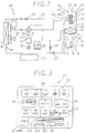
- FIGS. 1 through 14 A first embodiment in which the present invention is applied to an air conditioner for electric vehicles will now be described with reference to FIGS. 1 through 14.
- an air conditioning duct 2 in an air conditioning unit 1 forms an air passage therein for introducing air into a passenger compartment.
- an inside/outside air switching means 3 and air blowing means 4 are provided on one side, and a plurality of air outlets 14 through 16 is formed so as to open to the passenger compartment on the other side.
- the inside/outside air switching means 3 is provided with an inside/outside air switching door 7 within a inside/outside air switching box to selectively open/close the inside air inlet 5 for taking in the air from the inside of the passenger compartment (i.e., inside air) and an outside air inlet 6 for taking in air from the outside of the passenger compartment (i.e., outside air), both the inlets 5 and 6 being formed in the inside/outside air selected box and the inside/outside air selecting door 7 being driven by a dedicated driving means (e.g., servo motor, not illustrated).
- a dedicated driving means e.g., servo motor, not illustrated.
- the air blowing means 4 generates air flow in the air conditioning duct 2 from the inside air inlet 5 or outside air inlet 6 to the air outlets 14 through 16.
- a multiblade fan 9 is located in a scroll casing 8 and the multiblade fan 9 is driven by a blower motor 10.
- An indoor cooling heat exchanger 11 is located in the air conditioning duct 2 on the downstream side from the multiblade fan 9.
- the indoor cooling heat exchanger 11 forms a part of a refrigerating cycle 20 (described later) and functions when the operation is in a cooling mode (described later) as an evaporator for dehumidifying and cooling the air in the air conditioning duct 2 by the endothermic action of the refrigerant flowing therethrough.
- a heating mode however, the refrigerant does not flow into the indoor cooling heat exchanger 11.
- an indoor heating heat exchanger 12 is located in the air conditioning duct 2 on the downstream side from the indoor cooling heat exchanger 11.
- the indoor heating heat exchanger 12 forms a part of a refrigerating cycle 20 and functions when the operation is in a heating mode (described later) as a condenser for heating the air in the air conditioning duct 2 by the radiative action of the refrigerant flowing therethrough. When the operation is in the cooling mode, however, the refrigerant does not flow into the indoor heating heat exchanger 12.
- an air mix door 13 is located in a position adjacent to the indoor heating heat exchanger 12 in the air conditioning duct 2 to regulate the flow amount of the air supplied from the multiblade fan 9 to flow through the indoor heating heat exchanger 12 and the flow amount of the air supplied from the multiblade fan 9 to bypass the indoor heating heat exchanger 12.
- the above-described air outlets 14 through 16 are specifically a defroster air outlet 14 for blowing the conditioned air toward the inside surface of the vehicle windshield, a face air outlet 15 for blowing the conditioned air toward the upper half of the bodies of the driver and passengers in the passenger compartment, and a foot air outlet 16 for blowing the conditioned air toward the lower half of the driver and passengers in the passenger compartment.
- the refrigerating cycle 20 is a heat pump type cycle in which the inside of the passenger compartment is cooled or heated by the indoor cooling heat exchanger 11 and the indoor heating heat exchanger 12.
- the refrigerating cycle 20 includes a refrigerant compressor 21, an outdoor heat exchanger 22, a cooling pressure reducer 23 (cooling expansion valve), a heating pressure reducer 24 (heating expansion valve), accumulator 25 and a four-way valve 26 which selects the flow of the refrigerant, all of which is mutually connected with a refrigerant pipe 27.
- the reference numeral 28 denotes a solenoid valve
- the reference numeral 29 denotes an outdoor fan.
- the above-described outdoor heat exchanger functions as a condenser when the operation is in a cooling mode (described later).
- the refrigerant compressor 21 When the refrigerant compressor 21 is driven by an electric motor 30, the refrigerant compressor 21 takes in, compresses and exhaust the refrigerant.
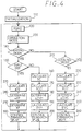
- the electric motor 30 is arranged integrally with the refrigerant compressor 21 in a sealed-up casing. The rotational speed of the electric motor 30 continuously varies by the control of an inverter 31. Power supply to the inverter 31 is controlled by an electronic control unit (ECU) 40 (FIG. 2).
- ECU electronice control unit
- both the cooling pressure reducer 23 and the heating pressure reducer 24 are electric type expansion valves in which each valve opening degree varies by control of the electronic control unit 40 (FIG. 2).
- signals are input from an outside air temperature sensor 41 for detecting the temperature of the outside air, an inlet temperature sensor 42 for detecting the temperature of the air of inlet side of the indoor heating heat exchanger 12 (specifically, inlet side of the indoor cooling heat exchanger 11), a discharge pressure sensor 43 for detecting the pressure of the refrigerant discharged from the refrigerant compressor 21, and a cooling outlet temperature sensor 44 for detecting the temperature of the refrigerant after passing through the outdoor heat exchanger 22.
- signals are input from a heating outlet temperature sensor 45 for detecting the refrigerant temperature of the refrigerant after passing through the indoor heating heat exchanger 12, a post-evaporator sensor 46 for detecting air cooling degree of the indoor cooling heat exchanger 11 (specifically, the temperature of the air immediately after passing through the indoor cooling heat exchanger 11), and a discharge temperature sensor 47 for detecting the temperature of the refrigerant discharged from the compressor 21.
- Signals from each lever and switch of a control panel 51 which is located at the front of the passenger compartment is also input into the ECU 40.
- the discharge pressure sensor 43 is located in a discharge pipe between the compressor 21 and the four-way valve 26. Further, the cooling outlet temperature sensor 44 is covered with a heat insulation material or the like, so that the error in the detection of the refrigerant temperature becomes small, then the cooling outlet temperature sensor 44 is closely fixed by a clamp or the like on the surface of the outlet pipe of the outdoor heat exchanger 22. Similarly, the heating outlet temperature sensor 45 is covered with a heat insulation material or the like, so that the error in the detection of the refrigerant temperature becomes small, then the heating outlet temperature sensor 45 is closely fixed by a clamp or the like on the surface of the outlet pipe of the indoor heating heat exchanger 12.
- the control panel 51 is provided with a blow mode setting switch 52 for setting blow mode, an air flow amount setting switch 53 for setting the flow amount of the air blown into the passenger compartment, an inside/outside air switching switch 54 for setting the inside/outside air mode, an operation mode setting switch 55 for setting the operation mode of the refrigerating cycle 20, a temperature setting lever 56 for setting the temperature of the air blown into the passenger compartment, and a power saving switch 57 for setting the power saving mode of the consumed electric power of the electric motor 30.
- a blow mode setting switch 52 for setting blow mode
- an air flow amount setting switch 53 for setting the flow amount of the air blown into the passenger compartment
- an inside/outside air switching switch 54 for setting the inside/outside air mode
- an operation mode setting switch 55 for setting the operation mode of the refrigerating cycle 20
- a temperature setting lever 56 for setting the temperature of the air blown into the passenger compartment
- a power saving switch 57 for setting the power saving mode of the consumed electric power of the electric motor 30.
- the blow mode setting switch 52 includes a face switch 52a selecting a face mode which blows the conditioned air from the face air outlet 15, a bi-level switch 52b selecting a bi-level mode which blows the conditioned air from the face air outlet 15 and the foot air outlet 16, a foot switch 52c selecting a foot mode which blows the conditioned air from the foot air outlet 16, a foot defroster switch 52d selecting a foot defroster mode which blows the conditioned air from the foot air outlet 16 and defroster air outlet 14, and a defroster switch 52e selecting a defroster mode which blows the conditioned air from the defroster air outlet 14.
- the defroster switch 52e is a switch which instructs prevention of cloud, defogging, and defrosting of the vehicle windshield.
- the operation mode setting switch 55 includes a stop switch 55a for stopping the operation of the compressor 21, a cooling switch 55b for setting the operation mode of the refrigerating cycle 20 to the cooling operation mode, a heating switch 55c for setting the operation mode of the refrigerating cycle 20 to the heating operation mode, and the like.
- the above-described temperature setting lever 56 sets a target temperature in the passenger compartment by a driver or a passenger in the passenger compartment. According to the setting position of the temperature setting lever 56, in the cooling operation mode, the ECU 40 determines the target value of the air cooling degree of the indoor cooling heat exchanger 11 (specifically, the temperature of the air immediately after passing through the indoor cooling heat exchanger 11). Further, according to the setting position of the temperature setting lever 56, in the heating operation mode, the ECU 40 determines the target value of the air heating degree of the indoor heating heat exchanger 12 (specifically, the temperature of the refrigerant discharged from the compressor 21).
- the ECU 40 controls the inverter 31 in such a way that the detected value of the post-evaporator sensor 46 is controlled to the target value in the cooling operation mode and the detected value of the discharge pressure sensor is controlled to the target value in the heating operation mode. Further, when the defroster switch 52e is input, the ECU 40 controls the servo motors to be set to the defroster mode.
- a well-known microcomputer which includes CPU, ROM, RAM and other components is incorporated in the ECU 40.
- the signal from each of the sensors 41 through 47 and the signals from the control panel 51 are input respectively into the microcomputer through an input circuit (not shown) in the ECU 40.
- This microcomputer executes a specified process (described herein later). Based on the results of the execution, the microcomputer controls the blower motor 10, the cooling pressure reducer 23, the heating pressure reducer 24, the solenoid valve 28, outdoor fan 29, the inverter 31, and the servo motors 32 through 34. Here, electric power is supplied to the ECU 40 from a battery (not shown).
- the microcomputer starts up the compressor 21 and controls the four-way valve 26 and the solenoid valve 28 in such a way that the refrigerating cycle 20 is set to the cooling operation mode.
- the refrigerant flows through the compressor 21, the outdoor heat exchanger 22, the cooling pressure reducer 23, the indoor cooling heat exchanger 11, the accumulator 25, and the compressor 21 in this order.
- the microcomputer starts up the compressor 21 and controls the four-way valve 26 and the solenoid valve 28 in such a way that the refrigerating cycle 20 is set to the cooling operation mode.
- the refrigerant flows through the compressor 21, the indoor heating heat exchanger 12, the heating pressure reducer 24, the outdoor heat exchanger 22, the solenoid valve 28, the accumulator 25, and the compressor 21 in this order.
- the routine shown in FIG. 4 starts.
- the initialization is performed.
- the step 120 the signals from the sensors 41 through 47 and the control panel 51 are read respectively.
- the operation mode of the refrigerating cycle 20 is determined. For example, when the cooling switch 55b is input, the refrigerating cycle 20 is determined to be the cooling operation mode, when the heating switch 55b is input, the refrigerating cycle 20 is determined to be the heating operation mode.
- step 140 it is determined whether or not the operation mode determined in the step 130 is in the heating operation mode. Further, in the step 150, it is determined whether or not the defroster switch 52e is in the on position.
- the steps 270 through 300 which is the main feature of the present invention, are performed.
- the determination is NO in any one of the steps 140 and 150, the steps 160 through 200 or the steps 210 through 260 are performed.
- the supercooling degree (SC) of the condensate refrigerant of the indoor heating heat exchanger 12 is firstly calculated by the following equation (1) in the step 160.
- SC f(Pd)-Tcs
- the f(Pd) is a condensed temperature which is calculated by detected value of the discharge pressure sensor 43
- Tcs is a detected value of the heating outlet temperature sensor 45.
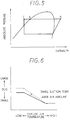
- the discharge refrigerant pressure which is detected by the discharge pressure sensor 43 is a pressure at the point "A” in the Mollier diagram (FIG. 5) of the refrigerating cycle 20. That is, the discharge refrigerant pressure is a pressure at the point "B".
- the condensed temperature at the point "B” is obtained by the map which shows the relationship between the condensed temperature and the refrigerant pressure (not shown) which is stored in ROM.
- the condensed temperature at the point "B” is the above-described f(Pd).
- the refrigerant temperature detected by the heating outlet temperature sensor 45 is a temperature at the point "C" in FIG. 5.
- SC the difference between the refrigerant temperature of the point "B” and the refrigerant temperature at the point "C" in FIG. 5 is calculated, that is, SC is calculated.
- the target value (SCO) of the supercooling degree is so calculated that the efficiency of refrigerating cycle 20 becomes as large as possible, to improve the power saving effect.
- the SCO is calculated by the signals from the outside air temperature sensor 41, the inlet temperature sensor 42, and the air flow amount setting switch 53. As shown in FIG. 6, the lower the outside air temperature and the inlet side air temperature of the indoor heating heat exchanger 12 and the larger air flow amount passing through the indoor heating heat exchanger 12 are, the larger SCO is.
- the outside air introduction mode is generally used for defrosting.
- the lower the outside air temperature is, the lower the inlet side air temperature of the indoor heating heat exchanger 12 is. That is, the temperature of the air passing through the indoor heating heat exchanger 12 becomes low.
- What the temperature of the air passing through the indoor heating heat exchanger 12 is low means that the difference between the temperature of the refrigerant in the indoor heating heat exchanger 12 and the temperature of the air passing through the indoor heating heat exchanger 12 is large, that is, the heat radiation ability Q is large.
- the SCO when the temperature of the air of the inlet side of the indoor heating heat exchanger 12 is low, if the SCO is calculated as a larger value, the increase of the heat radiation ability Q becomes larger than that of the power W so that the coefficient of performance (COP) becomes large.
- the SCO when the temperature of the air of the inlet side of the indoor heating heat exchanger 12 is high, if the SCO is calculated as a larger value, the COP becomes small. That is, as shown by the solid line in FIG. 7, when the temperature of the outside air is high, the SC having the largest COP becomes small. When the temperature of the outside air is low, the SC having the largest COP becomes large.
- the chain line with one dot in FIG. 7 is a line of connecting the points in which the COP becomes the largest.
- the SCO is calculated as a larger value, as compared with when the temperature of the outside air or the temperature of the inlet side is high,
- the basic pressure of high-pressure is lower as compared with a small flow amount of the air. Therefore, when the SCO is calculated as a larger value to increase the ability Q, although the power W becomes large, however, the basic power W is small. As a result, the coefficient of performance becomes large. Thus, when the flow amount of the air flowing through the indoor heating heat exchanger 12 is large, the SCO is calculated as a larger value.
- the upper limit EVH1 and the lower limit EVH2 of the ⁇ EVH are determined to prevent the hunting of the SC.
- the expansion valve opening degree EVH is calculated by adding the ⁇ EVH to the present expansion valve opening degree.
- the heating pressure reducer 24 is so controlled that the real opening degree becomes to the EVH. Then, it is returned to the step 120.
- the process is jumped to the step 210, then it is determined whether or not the operation mode which is determined in the step 130 is the cooling operation mode.
- the determination is NO in the step 210, that is, when the operation mode is not the heating operation mode and the cooling operation mode, it is returned to the step 120.
- the determination is YES in the step 210, the supercooling degree SC of the condensed liquid refrigerant in the outdoor heat exchanger 22 is calculated by the following equation (2) in the next step 220.
- SC f(Pd)-Tos wherein, Tos is a detected value of the cooling outlet temperature sensor 44.
- the target value (SCO) of the supercooling degree is calculated. As shown in FIG. 9, the higher the temperature of the fresh air or the larger the flow amount of the air flowing through the indoor cooling heat exchanger 11 is, the larger SCO is.
- the compressor 21 for cooling the passenger compartment is more operated to ensure the cooling ability.
- the high-pressure becomes high, so that the temperature of the refrigerant in the outdoor heat exchanger 22 becomes high.
- the difference of the temperature between the refrigerant temperature and the outside air temperature becomes large. That is, the heat radiation ability Q in the outdoor heat exchanger 22 becomes large.
- the SCO is calculated as a larger value, and as a result, the power W of the compressor 21 becomes large, the heat radiation ability Q becomes larger than the power W of the compressor 21. Therefore, when the temperature of the outside air is high, the coefficient of performance (COP) becomes large as compared with the case when the outside air is low, the SCO is calculated as a larger value.
- the SCO is calculated as a larger value, and as a result, the power W becomes large, the heat radiation ability Q becomes larger than the power W. Therefore, in such a case, the SCO is calculated as a larger value.
- secondly increase and decrease value ⁇ EVH of the valve opening degree of the cooling pressure reducer 23 according to the deviation ⁇ SC is calculated by the map in FIG. 10 which is stored in ROM.
- the upper limit EVH1 and the lower limit EVH2 of the ⁇ EVH are determined to prevent the hunting of the SC.
- the expansion valve opening degree EVH is calculated by adding the ⁇ EVH to the present expansion valve opening degree.
- the cooling pressure reducer 23 is so controlled that the real opening degree becomes to the EVH. Then, it is returned to the step 120.
- a deviation of the discharge temperature ⁇ Td is calculated by the following equation (3) in the step 270.
- Td1 is an discharge refrigerant temperature which is detected by the discharge temperature sensor 47
- T1 is a setting temperature which is set in advance as an enough temperature to perform the defrosting of the front windshield glass.
- the discharge refrigerant temperature is more than the T1
- the warm air passing through the indoor heating heat exchanger 12 is blown from the defroster air outlet 14 toward the inside surface of the front windshield glass, so that the defrosting of the front windshield glass can be sufficiently performed.
- the increase and decrease value ⁇ KF of a valve opening degree of the heating pressure reducer 24 according to the deviation ⁇ Td of the discharge temperature which is calculated in the step 270 is determined by searching from the map in FIG. 11 which is stored in ROM.
- the opening degree KF of the heating expansion valve is calculated by adding the ⁇ KF to the present expansion valve opening degree.
- the heating pressure reducer 24 is so controlled that the real opening degree becomes to the opening degree KF. Then, it is returned to the step 120.
- the map in FIG. 11 is so prepared that the increase and decrease value ⁇ KF becomes less than zero when the deviation ⁇ Td of the discharge temperature is less than zero, and the ⁇ KF equals 0 when the ⁇ Td equals 0.
- the opening degree of the heating pressure reducer 24 becomes small until the ⁇ Td becomes zero, that is, until the discharge refrigerant temperature of the compressor 21 becomes the setting temperature T1.
- the opening degree of the heating pressure reducer 24 becomes small.
- the opening degree (the second opening) of the heating pressure reducer 24 in the defrosting is smaller than the opening degree (the first opening) of the heating pressure reducer 24 in the ordinary heating mode.
- the SC becomes large as described above, the COP is decreased, however, on the other hand, the discharge refrigerant pressure and the discharge air temperature in the passenger compartment become high. That is, in the first embodiment, in the defrosting, the SC is increased until the discharge refrigerant temperature of the compressor 21 becomes to the setting temperature T1. As a result, the discharge air temperature becomes high.
- the opening degree (the second opening degree) of the heating pressure reducer 24 in the defrosting is larger than the opening degree (the first opening degree) of the heating pressure reducer 24 in the ordinary heating mode.
- FIG. 13 an experimental data when the outside air temperature is 0°C and the heat abstraction ability Q is 3.15KW are shown, and in FIG. 14, an experimental data when the outside air temperature is -18°C is shown.
- the opening degree of the pressure reducer 23 or 24 is so controlled that the COP is maximized.
- the defroster switch 52e is input in the defrosting mode, even if the heating pressure reducer 24 is so controlled that the COP becomes a little smaller, the discharge air temperature is made high. Therefore, in the first embodiment, while performing the power saving operation in the ordinary operation mode, the defrosting of the front windshield glass can be sufficiently performed.
- the opening degree of the heating pressure reducer 24 when the defroster switch 52e is input is not controlled to be excessively small to increase the defrosting effect, the opening degree is made small until the discharge refrigerant temperature Td1 becomes to the setting temperature T1. Therefore, the increase of the consumed electric power of the compressor accompanied with the decrease of the opening degree of the pressure reducer can be minimized as needed.
- the setting temperature T1 in the step 270 is so set that the defrosting of the front windshield glass can be sufficiently performed.
- the amount of electric current input to the inverter 31 or the amount of the electric current output from the inverter 31 is detected, the setting temperature T1 in the step 270 may be so set that the amount of the electric current becomes to a predetermined value.
- the predetermined amount of the electric current in the second embodiment is a temperature in which the amount of heat generated by the inverter 31 becomes an upper limit of the tolerance.
- the amount of the heat generated by the inverter 31 is controlled, so that the inverter 31 can be normally kept on operating.
- the opening degree (the second opening degree) of the heating pressure reducer 24 in the defrosting is smaller than the opening degree (the first opening degree) of the heating pressure reducer 24 in the ordinary heating mode.
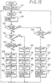
- a step 155 is further performed between the step 150 and the step 270 in the above embodiment.
- the process of the steps 270 through 300 may be performed.
- the opening degree of the pressure reducer is so controlled that the supercooling degree SC becomes the target supercooling degree.
- means for detecting the air heating degree in the indoor heating heat exchanger 12 is further provided, and in the ordinary operation mode in which the operation for the prevention of the cloud, defogging, or defrosting is not operated, the opening degree of the pressure reducer (the first opening) may be so controlled that the COP is maximized based on the detected value of the detecting means.
- the opening degree of the pressure reducer (the second opening degree) may be so controlled that the detected value of the detecting means corresponds to a predetermined temperature where the operation for the prevention of cloud, the defogging, or the defrosting of the front windshield glass can be performed, or the discharge refrigerant temperature becomes the setting temperature T1 as shown in the first embodiment, or the electric current supplied to the inverter 31 becomes the predetermined value as shown in the second embodiment, or which are combined with each other.
- the opening degree (the second opening degree) of the heating pressure reducer 24 in the defrosting mode becomes smaller than the opening degree (the first opening) of the heating pressure reducer 24 in the ordinary heating mode.
- the condenser (indoor heating heat exchanger 12) is located in the air conditioning duct 2, the air in the air conditioning duct 2 is directly heated by the heat of the condensation of the condenser.
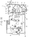
- the condenser is constructed by a refrigerant water heat exchanger 21 which heat exchanges with warm water in a warm water circuit, the heat of the condensation heat generated in the refrigerant water heat exchanger 21 is supplied to the warm water in the warm water circuit 10 to heat the warm water.
- the air in the air conditioning duct 2 may be heated by flowing the warm water into a warm water type heat exchanger 11 which is located in the air conditioning duct 2.
- the reference numeral 33 denotes a fuel type heater
- the reference numeral 32 denotes a water pump
- the reference numeral 34 denotes a warm pipe
- the reference numerals 26 and 27 denote solenoid valves.
- the setting temperature T1 used in the step 270 may be set as a temperature in which the compressor 21 can be preserved.
- the increase and decrease value of the valve opening degree may be calculated based on the pressure deviation of high-pressure.
- the defrosting effect can be increased to the extent that an abnormal high pressure is not applied the indoor heating heat exchanger 12 or the heating pressure reducer 24.
- the defrosting instruction signals generating means may be constructed with such as a sensor for outputting a signal when the cloud degree of the front windshield glass is more than a predetermined value.
- the present invention is applied to an air conditioner for electric vehicles.
- the present invention may be applied to an air conditioner for engine driving vehicles and for rooms in a house or building.
Landscapes
- Physics & Mathematics (AREA)
- Thermal Sciences (AREA)
- Engineering & Computer Science (AREA)
- Mechanical Engineering (AREA)
- Air-Conditioning For Vehicles (AREA)
Applications Claiming Priority (4)
| Application Number | Priority Date | Filing Date | Title |
|---|---|---|---|
| JP157622/95 | 1995-06-23 | ||
| JP15762295 | 1995-06-23 | ||
| JP91440/96 | 1996-04-12 | ||
| JP8091440A JPH0966736A (ja) | 1995-06-23 | 1996-04-12 | 車両用空調装置 |
Publications (2)
| Publication Number | Publication Date |
|---|---|
| EP0749856A2 true EP0749856A2 (fr) | 1996-12-27 |
| EP0749856A3 EP0749856A3 (fr) | 1999-01-27 |
Family
ID=26432880
Family Applications (1)
| Application Number | Title | Priority Date | Filing Date |
|---|---|---|---|
| EP96110048A Withdrawn EP0749856A3 (fr) | 1995-06-23 | 1996-06-21 | Dispositif de climatisation |
Country Status (3)
| Country | Link |
|---|---|
| US (1) | US5669231A (fr) |
| EP (1) | EP0749856A3 (fr) |
| JP (1) | JPH0966736A (fr) |
Cited By (2)
| Publication number | Priority date | Publication date | Assignee | Title |
|---|---|---|---|---|
| FR2957850A1 (fr) * | 2010-03-26 | 2011-09-30 | Valeo Systemes Thermiques | Dispositif de chauffage, ventilation et/ou climatisation pour vehicule automobile |
| CN110375466A (zh) * | 2018-04-13 | 2019-10-25 | 开利公司 | 用于空气源热泵系统的制冷剂泄露的检测装置和方法 |
Families Citing this family (29)
| Publication number | Priority date | Publication date | Assignee | Title |
|---|---|---|---|---|
| US5996360A (en) * | 1997-11-27 | 1999-12-07 | Denso Corporation | Refrigerant cycle system |
| EP1148307B1 (fr) * | 2000-04-19 | 2004-03-17 | Denso Corporation | Chauffe-eau avec pompe à chaleur |
| US6370903B1 (en) | 2001-03-14 | 2002-04-16 | Visteon Global Technologies, Inc. | Heat-pump type air conditioning and heating system for fuel cell vehicles |
| US6658871B1 (en) | 2001-04-23 | 2003-12-09 | Airsept, Inc. | Electronic evaporator dryer for eliminating odors in vehicle air conditioning systems |
| JP2003326959A (ja) * | 2002-05-09 | 2003-11-19 | Denso Corp | 車両用空調装置 |
| JP2005224075A (ja) * | 2004-02-09 | 2005-08-18 | Sanyo Electric Co Ltd | インバータ装置 |
| US8152485B2 (en) * | 2005-01-10 | 2012-04-10 | Hsia-Yuan Hsu | DC brushless motor pump |
| US20060153714A1 (en) * | 2005-01-10 | 2006-07-13 | Hsiang-Yuan Hsu | Brushless motor pump |
| JP3900186B2 (ja) * | 2005-02-10 | 2007-04-04 | 松下電器産業株式会社 | ヒートポンプ給湯機 |
| JP2007225169A (ja) * | 2006-02-22 | 2007-09-06 | Denso Corp | 空調装置 |
| JP4948374B2 (ja) * | 2007-11-30 | 2012-06-06 | 三菱電機株式会社 | 冷凍サイクル装置 |
| JP5042058B2 (ja) * | 2008-02-07 | 2012-10-03 | 三菱電機株式会社 | ヒートポンプ式給湯用室外機及びヒートポンプ式給湯装置 |
| JP4497234B2 (ja) * | 2008-07-29 | 2010-07-07 | ダイキン工業株式会社 | 空気調和装置 |
| JP5404487B2 (ja) * | 2010-03-23 | 2014-01-29 | 三菱電機株式会社 | 多室形空気調和機 |
| FR2957851B1 (fr) * | 2010-03-26 | 2012-04-13 | Valeo Systemes Thermiques | Dispositif de chauffage, ventilation et/ou climatisation pour vehicule automobile |
| JP5005122B2 (ja) | 2010-04-23 | 2012-08-22 | パナソニック株式会社 | 車両用空調装置 |
| JP5510418B2 (ja) * | 2011-09-05 | 2014-06-04 | 株式会社デンソー | 車両用空調装置 |
| EP2787305B1 (fr) * | 2011-11-29 | 2019-09-04 | Mitsubishi Electric Corporation | Dispositif de réfrigération/climatisation |
| JP5962377B2 (ja) * | 2012-09-21 | 2016-08-03 | 株式会社デンソー | 電動車両用空調装置 |
| JP6052028B2 (ja) * | 2013-04-03 | 2016-12-27 | 株式会社デンソー | モータ制御装置 |
| JP6228066B2 (ja) * | 2014-04-18 | 2017-11-08 | サンデンホールディングス株式会社 | 冷凍装置 |
| CN104329776B (zh) * | 2014-11-17 | 2017-09-29 | 国家电网公司 | 电动汽车的空调控制方法及装置 |
| JP6680191B2 (ja) | 2016-11-16 | 2020-04-15 | 株式会社デンソー | 車両用空調装置 |
| JP6900186B2 (ja) * | 2016-12-21 | 2021-07-07 | サンデン・オートモーティブクライメイトシステム株式会社 | 車両用空気調和装置 |
| JP2018103879A (ja) * | 2016-12-27 | 2018-07-05 | サンデン・オートモーティブクライメイトシステム株式会社 | 車両用空気調和装置 |
| US11267318B2 (en) * | 2019-11-26 | 2022-03-08 | Ford Global Technologies, Llc | Vapor injection heat pump system and controls |
| CN113074452A (zh) * | 2021-03-19 | 2021-07-06 | 海信(山东)空调有限公司 | 空调器的除霜控制方法、空调器和存储介质 |
| US12023983B2 (en) * | 2021-03-24 | 2024-07-02 | Ford Global Technologies, Llc | Methods and systems for instant cabin heat for a vehicle |
| CN115540213B (zh) * | 2022-09-13 | 2025-01-17 | 青岛海尔空调电子有限公司 | 一种空调器的除霜控制方法、装置、系统及空调器 |
Family Cites Families (12)
| Publication number | Priority date | Publication date | Assignee | Title |
|---|---|---|---|---|
| JPS5827848Y2 (ja) * | 1979-10-11 | 1983-06-17 | 株式会社ボッシュオートモーティブ システム | 自動車用空気調和装置の制御装置 |
| DE3624171A1 (de) * | 1986-07-17 | 1988-01-21 | Bosch Gmbh Robert | Heiz- und/oder klimaanlage fuer kraftfahrzeuge |
| DE3726122C1 (de) * | 1987-08-06 | 1988-12-22 | Daimler Benz Ag | Verfahren zur Regelung von Parametern der Innenraumluft in einem Kraftfahrzeug mit einer Klimaanlage |
| DE3739372A1 (de) * | 1987-11-20 | 1989-06-01 | Sueddeutsche Kuehler Behr | Klimaanlage |
| JPH01311915A (ja) * | 1988-06-10 | 1989-12-15 | Diesel Kiki Co Ltd | 自動車用空調制御装置 |
| JP2904354B2 (ja) * | 1989-11-30 | 1999-06-14 | 三菱電機株式会社 | 空気調和機 |
| US4966012A (en) * | 1989-12-05 | 1990-10-30 | Diesel Kiki Co., Ltd. | Air-conditioner for automobile |
| US5316074A (en) * | 1990-10-12 | 1994-05-31 | Nippondenso Co., Ltd. | Automotive hair conditioner |
| US5299431A (en) * | 1991-04-26 | 1994-04-05 | Nippondenso Co., Ltd. | Automotive air conditioner having condenser and evaporator provided within air duct |
| US5375427A (en) * | 1993-01-29 | 1994-12-27 | Nissan Motor Co., Ltd. | Air conditioner for vehicle |
| DE69503822T2 (de) * | 1994-04-21 | 1999-04-01 | Denso Corp., Kariya, Aichi | Klimaanlage |
| JP3452644B2 (ja) * | 1994-07-06 | 2003-09-29 | サンデン株式会社 | 車両用空気調和装置 |
-
1996
- 1996-04-12 JP JP8091440A patent/JPH0966736A/ja active Pending
- 1996-06-21 EP EP96110048A patent/EP0749856A3/fr not_active Withdrawn
- 1996-06-21 US US08/667,512 patent/US5669231A/en not_active Expired - Fee Related
Cited By (4)
| Publication number | Priority date | Publication date | Assignee | Title |
|---|---|---|---|---|
| FR2957850A1 (fr) * | 2010-03-26 | 2011-09-30 | Valeo Systemes Thermiques | Dispositif de chauffage, ventilation et/ou climatisation pour vehicule automobile |
| CN110375466A (zh) * | 2018-04-13 | 2019-10-25 | 开利公司 | 用于空气源热泵系统的制冷剂泄露的检测装置和方法 |
| CN110375466B (zh) * | 2018-04-13 | 2022-10-28 | 开利公司 | 用于空气源热泵系统的制冷剂泄露的检测装置和方法 |
| US11732939B2 (en) | 2018-04-13 | 2023-08-22 | Carrier Corporation | Detection apparatus and method for refrigerant leakage of air source heat pump system |
Also Published As
| Publication number | Publication date |
|---|---|
| JPH0966736A (ja) | 1997-03-11 |
| US5669231A (en) | 1997-09-23 |
| EP0749856A3 (fr) | 1999-01-27 |
Similar Documents
| Publication | Publication Date | Title |
|---|---|---|
| US5669231A (en) | Air conditioning apparatus | |
| US6237351B1 (en) | Heat pump type refrigerant cycle system | |
| US6293123B1 (en) | Refrigeration cycle device | |
| US5701753A (en) | Air conditioning apparatus | |
| US5904052A (en) | Brine type air conditioning apparatus | |
| EP0788910B1 (fr) | Dispositif de climatisation pour véhicule avec améliorations empêchant la formation de givre | |
| JPH1134640A (ja) | 車両用空調装置 | |
| US5706667A (en) | Air conditioning apparatus | |
| JP2001324237A (ja) | 冷凍サイクル装置 | |
| CN114126900A (zh) | 车用空调设备 | |
| US5709098A (en) | Air conditioning apparatus | |
| US7082990B1 (en) | Air conditioning apparatus for vehicle | |
| JPH058631A (ja) | 車両用空調装置 | |
| JP3704814B2 (ja) | 車両用空気調和装置 | |
| JP3334446B2 (ja) | 車両用空調装置 | |
| JP3063574B2 (ja) | 空調装置 | |
| JP2001050572A (ja) | 自動車用空気調和装置 | |
| JP5533516B2 (ja) | 車両用空調装置 | |
| JP2009166629A (ja) | 車両用空調装置 | |
| JP3063575B2 (ja) | 冷凍サイクル制御装置 | |
| JP3404990B2 (ja) | 車両用ヒートポンプ式冷暖房装置 | |
| CN110049887A (zh) | 车辆用空气调和装置 | |
| JPH08216655A (ja) | 車両用ヒートポンプ式空調装置 | |
| JPH1086654A (ja) | ブライン式空調装置 | |
| JP3456021B2 (ja) | 車両用空気調和装置 |
Legal Events
| Date | Code | Title | Description |
|---|---|---|---|
| PUAI | Public reference made under article 153(3) epc to a published international application that has entered the european phase |
Free format text: ORIGINAL CODE: 0009012 |
|
| AK | Designated contracting states |
Kind code of ref document: A2 Designated state(s): DE FR IT |
|
| RAP1 | Party data changed (applicant data changed or rights of an application transferred) |
Owner name: DENSO CORPORATION |
|
| PUAL | Search report despatched |
Free format text: ORIGINAL CODE: 0009013 |
|
| AK | Designated contracting states |
Kind code of ref document: A3 Designated state(s): DE FR IT |
|
| 17P | Request for examination filed |
Effective date: 19990705 |
|
| 17Q | First examination report despatched |
Effective date: 20020726 |
|
| STAA | Information on the status of an ep patent application or granted ep patent |
Free format text: STATUS: THE APPLICATION IS DEEMED TO BE WITHDRAWN |
|
| 18D | Application deemed to be withdrawn |
Effective date: 20021206 |