EP0788910B1 - Dispositif de climatisation pour véhicule avec améliorations empêchant la formation de givre - Google Patents
Dispositif de climatisation pour véhicule avec améliorations empêchant la formation de givre Download PDFInfo
- Publication number
- EP0788910B1 EP0788910B1 EP96115036A EP96115036A EP0788910B1 EP 0788910 B1 EP0788910 B1 EP 0788910B1 EP 96115036 A EP96115036 A EP 96115036A EP 96115036 A EP96115036 A EP 96115036A EP 0788910 B1 EP0788910 B1 EP 0788910B1
- Authority
- EP
- European Patent Office
- Prior art keywords
- heat exchanger
- air
- frost
- amount
- outside air
- Prior art date
- Legal status (The legal status is an assumption and is not a legal conclusion. Google has not performed a legal analysis and makes no representation as to the accuracy of the status listed.)
- Expired - Lifetime
Links
Images


Classifications
-
- B—PERFORMING OPERATIONS; TRANSPORTING
- B60—VEHICLES IN GENERAL
- B60H—ARRANGEMENTS OF HEATING, COOLING, VENTILATING OR OTHER AIR-TREATING DEVICES SPECIALLY ADAPTED FOR PASSENGER OR GOODS SPACES OF VEHICLES
- B60H1/00—Heating, cooling or ventilating devices
- B60H1/32—Cooling devices
- B60H1/3204—Cooling devices using compression
- B60H1/3205—Control means therefor
- B60H1/3207—Control means therefor for minimizing the humidity of the air
-
- B—PERFORMING OPERATIONS; TRANSPORTING
- B60—VEHICLES IN GENERAL
- B60H—ARRANGEMENTS OF HEATING, COOLING, VENTILATING OR OTHER AIR-TREATING DEVICES SPECIALLY ADAPTED FOR PASSENGER OR GOODS SPACES OF VEHICLES
- B60H1/00—Heating, cooling or ventilating devices
- B60H1/00642—Control systems or circuits; Control members or indication devices for heating, cooling or ventilating devices
- B60H1/00814—Control systems or circuits characterised by their output, for controlling particular components of the heating, cooling or ventilating installation
- B60H1/00878—Control systems or circuits characterised by their output, for controlling particular components of the heating, cooling or ventilating installation the components being temperature regulating devices
- B60H1/00899—Controlling the flow of liquid in a heat pump system
- B60H1/00907—Controlling the flow of liquid in a heat pump system where the flow direction of the refrigerant changes and an evaporator becomes condenser
-
- B—PERFORMING OPERATIONS; TRANSPORTING
- B60—VEHICLES IN GENERAL
- B60H—ARRANGEMENTS OF HEATING, COOLING, VENTILATING OR OTHER AIR-TREATING DEVICES SPECIALLY ADAPTED FOR PASSENGER OR GOODS SPACES OF VEHICLES
- B60H1/00—Heating, cooling or ventilating devices
- B60H1/00642—Control systems or circuits; Control members or indication devices for heating, cooling or ventilating devices
- B60H1/00814—Control systems or circuits characterised by their output, for controlling particular components of the heating, cooling or ventilating installation
- B60H1/00878—Control systems or circuits characterised by their output, for controlling particular components of the heating, cooling or ventilating installation the components being temperature regulating devices
- B60H2001/00935—Control systems or circuits characterised by their output, for controlling particular components of the heating, cooling or ventilating installation the components being temperature regulating devices comprising four way valves for controlling the fluid direction
-
- B—PERFORMING OPERATIONS; TRANSPORTING
- B60—VEHICLES IN GENERAL
- B60H—ARRANGEMENTS OF HEATING, COOLING, VENTILATING OR OTHER AIR-TREATING DEVICES SPECIALLY ADAPTED FOR PASSENGER OR GOODS SPACES OF VEHICLES
- B60H1/00—Heating, cooling or ventilating devices
- B60H1/00642—Control systems or circuits; Control members or indication devices for heating, cooling or ventilating devices
- B60H1/00814—Control systems or circuits characterised by their output, for controlling particular components of the heating, cooling or ventilating installation
- B60H1/00878—Control systems or circuits characterised by their output, for controlling particular components of the heating, cooling or ventilating installation the components being temperature regulating devices
- B60H2001/00961—Control systems or circuits characterised by their output, for controlling particular components of the heating, cooling or ventilating installation the components being temperature regulating devices comprising means for defrosting outside heat exchangers
Definitions
- the present invention relates to an air conditioner for a vehicle, in which a condenser and an evaporator both for forming a refrigeration cycle are employed as an indoor heat exchanger and an outdoor heat exchanger, respectively, so as to heat a passenger compartment of the vehicle by the heat of condensation in the condenser.
- the outdoor heat exchanger functions as an evaporator in a heating operation. Accordingly, in the case that the temperature of outside air is low (e.g., near 0° C) and the humidity is high, frost is deposited on the outdoor heat exchanger. If the heating operation is continued in such a frost deposition condition, the frost is growing with the elapse of the operation time, causing a reduction in heating capacity (coefficient of performance, COP).
- COP coefficient of performance
- JP-A-4-278153 when frost is deposited on an outdoor heat exchanger, a defrosting operation is performed in such a manner that the opening degree of an expansion valve is increased and the amount of air to be supplied to an indoor heat exchanger is reduced.
- both the indoor heat exchanger and the outdoor heat exchanger function as a condenser.
- the amount of air to be supplied to the indoor heat exchanger is reduced, a radiated heat amount in the indoor heat exchanger is reduced, and correspondingly a radiated heat amount in the outdoor heat exchanger is increased. In this way, the frost deposited on the outdoor heat exchanger is melted, while keeping on heating the passenger compartment by the indoor heat exchanger.
- an indoor heat exchanger functions as a condenser and an outdoor heat exchanger functions as an evaporator in a heating operation so as to heat the passenger compartment.
- a defrosting operation for the outdoor heat exchanger by opening a bypass tube for introducing a refrigerant discharged from a compressor directly to the outdoor heat exchanger so as to bypass the indoor heat exchanger and an expansion valve, a part of the refrigerant discharged from the compressor is supplied to the outdoor heat exchanger.
- the outdoor heat exchanger then functions as a condenser, and the frost is melted by the heat of condensation in the outdoor heat exchanger.
- the inside/outside air select mode at this time is an outside air introduction mode
- the outside air introduction mode is changed to a 1/3 outside air introduction mode.
- the amount of cool outside air introduced from an outside air inlet is reduced to about 1/3 of the air amount in the full outside air introduction mode, and warm inside, an amount of which corresponds to the remaining 2/3 of the air amount in the full outside air introduction mode, is introduced.
- warmer air can be supplied into the passenger compartment.
- both the indoor heat exchanger and the outdoor heat exchanger function as condensers to defrost the outdoor heat exchanger. Accordingly, heat of the refrigerant discharged from the compressor is radiated in both the indoor heat exchanger and the outdoor heat exchanger. In other words, the radiated heat amount in the indoor heat exchanger decreases according to the radiated heat amount in the outdoor heat exchanger. As a result, the heating capacity for the passenger compartment is reduced, thus decreasing the temperature in the passenger compartment.
- a heating operation period is generally long (e.g., 10 hours). Accordingly, a defrosting operation for a relatively short period (e.g., 30 minutes) has little influence upon a reduction in temperature of the room.
- the heating operation period corresponds to an operation period of the vehicle, which is much shorter (e.g., one hour) than the heating operation period of the air conditioner for the home. Accordingly, when a defrosting operation is performed for 30 minutes, for example, in the heating operation for such a short time, the influence upon a reduction in the temperature of the passenger compartment becomes greater than that in the case of the air conditioner for the home.
- the above heating operation is continued for at least a predetermined time period, and an amount of ventilating air of outside air sucked from an outside air inlet and blown out into a passenger compartment is reduced from an amount of the ventilating air before the frost deposition has been or may be determined.
- the above predetermined time period may be set as a time period until a deposited frost amount on the outdoor heat exchanger reaches a deposited frost limit, that is, until the frost deposition proceeds to such an extent that a temperature of the passenger compartment cannot be maintained at a set temperature even at a maximum rotating speed of a compressor.
- the first term (K x ⁇ T) in the right side represents heat loss by heat transfer
- the second term (Va x Cp x ⁇ x ⁇ T) in the right side represents heat loss by the ventilation.
- the heating load Q decreases with a decrease in the ventilating air amount Va. Further, it is generally known that an endothermic amount QE in the outdoor heat exchanger functioning as an evaporator decreases with a decrease in the heating load Q.
- Equation (1) and Equation (2) the endothermic amount QE in the outdoor heat exchanger decreases with a decrease in the ventilating air amount Va, so that the frost deposition speed x also decreases.
- Equation (3) the relationship between the size A of the outdoor heat exchanger and the absorbed heat amount QE satisfies Equation (3), and the relationship between the deposited frost limit X and the size A of the outdoor heat exchanger satisfies Equation (4).
- Equation (3) the relationship between the size A of the outdoor heat exchanger and the absorbed heat amount QE satisfies Equation (3), and the relationship between the deposited frost limit X and the size A of the outdoor heat exchanger satisfies Equation (4).
- the deposited frost limit X is defined as a deposited frost amount in which the temperature of passenger compartment cannot be maintained at the set temperature even at the maximum rotating speed of the compressor as mentioned above.
- Equation (3) the deposited frost limit X and the endothermic amount QE may be related with each other by the following Equation (5).
- Equation (5) X ⁇ 1/QE
- the deposited frost limit X increases with a decrease in the endothermic amount QE.
- the frost deposition speed on the outdoor heat exchanger is reduced, and the deposited frost limit is increased from X1 to X2 as shown by the solid lines in FIG. 6. Accordingly, as compared with the case that the heating operation is continued without reducing the ventilating air amount (as shown by the one-dotted chain lines in FIG. 6), the time until the deposited frost amount X' reached the deposited frost limit can be extended. That is, the time period during which the heating operation is continued can be prolonged.
- the above heating operation is continued for at least a predetermined period, and a radiated heat amount in the indoor heat exchanger is reduced from the radiated heat amount before the frost deposition has been determined.
- the radiated heat amount in the indoor heat exchanger in the above heating operation may be reduced by any methods such as by reducing an amount of air (outside air or inside air) passing through the indoor heat exchanger or by raising the temperature of the air.
- a higher-pressure in the refrigeration cycle is increased during the predetermined period, and a lower-pressure in the refrigeration cycle is accordingly also increased. Since the lower-pressure is increased, the temperature of the outdoor heat exchanger functioning as an evaporator is increased. As a result, the frost deposition speed on the outdoor heat exchanger is reduced, and the deposited frost limit is accordingly increased.
- the time until the deposited frost amount on the outdoor heat exchanger reaches the deposited frost limit can be prolonged.
- FIGS. 1 to 6 A first embodiment of the present invention applied to an air conditioner for an electric vehicle will now be described with reference to FIGS. 1 to 6.
- An air conditioning duct 2 in an air conditioning unit 1 shown in FIG. 1 constitutes an air passage for introducing air into a passenger compartment.
- Inside/outside air selecting means 3 and blowing means 4 are provided at one end of the air conditioning duct 2, and plural air outlets 14 to 16 are formed at the other end of the air conditioning duct 2.
- the inside/outside air selecting means 3 is constructed such that an inside/outside air selector door 7 for selectively opening and closing the air inlets 5 and 6 is provided in an inside/outside air selector box having an inside air inlet 5 for sucking air (inside air) inside the passenger compartment and an outside air inlet 6 for sucking air (outside air) outside the passenger compartment.
- the inside/outside air selector door 7 is driven by an inside/outside air selector switch 54 as shown in FIG. 3 (which will be described later) via a manual operating mechanism (not shown).
- the blowing means 4 functions to generate an air flow in the air conditioning duct 2 from the inside air inlet 5 or the outside air inlet 6 toward the air outlets 14 to 16. More specifically, the blowing means 4 is constructed of a scroll casing 8, a multiblade fan 9 provided in the scroll casing 8, and a blower motor 10 for driving the fan 9.
- a cooling indoor heat exchanger 11 is provided in the air conditioning duct 2 at a downstream air side of the fan 9.
- the cooling indoor heat exchanger 11 is a heat exchanger for forming a part of a refrigeration cycle 20, and functions as an evaporator for dehumidifying and cooling the air in the air conditioning duct 2 by the endothermic action of a refrigerant flowing in the evaporator in a cooling operation mode which will be described later.
- a heating operation mode (which will be described later)
- no refrigerant flows in the cooling indoor heat exchanger 11.
- a heating indoor heat exchanger 12 is provided in the air conditioning duct 2 at a downstream air side of the cooling indoor heat exchanger 11.
- the heating indoor heat exchanger 12 is a heat exchanger for forming a part of the refrigeration cycle 20, and functions as a condenser for heating the air in the air conditioning duct 2 by the heat radiating action of the refrigerant flowing in the condenser in the heating operation mode to be hereinafter described.
- the cooling operation mode (which will be described later) no refrigerant flows in the heating indoor heat exchanger 12.
- An air mix door 13 is provided in the air conditioning duct 2 at a position adjacent to the heating indoor heat exchanger 12 to adjust an amount of air supplied from the fan 9 and flowing into the indoor heat exchanger 12 for heating and an amount of air supplied from the fan 9 and bypassing the heating indoor heat exchanger 12.
- the air outlets 14 to 16 are specifically a defroster air outlet 14 for discharging the conditioned air toward the inner surface of a windshield glass of the vehicle, a face air outlet 15 for discharging the conditioned air toward the upper half of the body of a passenger in the passenger compartment, and a foot air outlet 16 for discharging the conditioned air toward the lower half of the body of the passenger in the passenger compartment.
- Doors 17, 18, and 19 for opening and closing the air outlets 14, 15, and 16 are provided at an upstream air side of these air outlets, respectively.
- the refrigeration cycle 20 is a heat pump type refrigeration cycle for performing cooling and heating of the interior of the passenger compartment by the cooling indoor heat exchanger 11 and the heating indoor heat exchanger 12.
- the refrigeration cycle 20 is provided with a refrigerant compressor 21, an outdoor heat exchanger 22, an expansion valve 23 for cooling, an expansion valve 24 for heating, an accumulator 25, a four-way valve 26 for selecting a refrigerant flow, and a refrigerant piping 27 for connecting these components with each other.
- reference numerals 28 and 29 denote an electromagnetic valve and an outdoor fan, respectively.
- the outdoor heat exchanger 22 is a heat exchanger functioning as a condenser in the cooling operation mode (which will be described later) and functioning as an evaporator in the heating operation mode (which will be described later).
- the refrigerant compressor 21 functions to suck, compress, and discharge the refrigerant when driven by an electric motor 30.
- the electric motor 30 is located integrally with the refrigerant compressor 21 in a sealed case, and is controlled by an inverter 31 to continuously change its rotating speed.
- the inverter 31 is controlled by changing an electric current thereto with a control device 40 (FIG. 2).
- the expansion valve 23 for cooling functions to expand the refrigerant flowing from the outdoor heat exchanger 22 into the cooling indoor heat exchanger 11 and reduce the pressure of the refrigerant in the cooling operation mode (which will be described later).
- the expansion valve 24 for heating functions to expand the refrigerant flowing from the heating indoor heat exchanger 12 into the outdoor heat exchanger 22 and reduce the pressure of the refrigerant in the heating operation mode (which will be described later).
- the control device 40 receives various signals from a discharge pressure sensor 41 for detecting a discharge pressure of the refrigerant discharged by the compressor 21, a suction pressure sensor 42 for detecting a suction pressure of the refrigerant to be sucked by the compressor 21, and a post-evaporator sensor 43 for detecting an air cooling degree in the cooling indoor heat exchanger 11 (more specifically, a temperature of air just after passed through the heat exchanger 11).
- the control device 40 further receives signals from levers and switches of a control panel 51 provided on the front surface in the passenger compartment.
- the control device 40 incorporates a known microcomputer including a CPU, ROM, RAM, input/output ports, etc. (not shown).
- the signals from the above-mentioned sensors 41 to 43 and the control panel 51 are input through an input circuit (not shown) in an ECU into the microcomputer.
- the microcomputer executes a predetermined process (which will be described later) according to the input signals, and controls the blower motor 10, the expansion valve 23 for cooling, the expansion valve 24 for heating, the four-way valve 26, the electromagnetic valve 28, the outdoor fan 29, and the inverter 31 according to the result of the process.
- the control device 40 is supplied with electric power from a battery (not shown) when a key switch (not shown) in the vehicle is turned on.
- the control panel 51 is provided with an air outlet mode setting switch 52 for setting an air outlet mode, an air flow setting switch 53 for setting a flow of air blowing into the passenger compartment, an inside/outside air selector switch 54 for setting an inside/outside air select mode, an operation mode setting switch 55 for setting an operation mode of the refrigeration cycle 20, and a temperature setting lever 56 for setting a temperature of air blowing into the passenger compartment.
- the operation mode setting switch 55 consists of a cooling switch 55a for setting the operation mode of the refrigeration cycle 20 to a cooling operation mode and a heating switch 55b for setting the operation mode of the refrigeration cycle 20 to a heating operation mode.
- step 110 signals from the discharge pressure sensor 41, the post-evaporator sensor 43, and the levers and switches of the control panel 51 are read in.
- step 115 it is determined whether or not the cooling switch 55a is on. If the determination is YES in step 115, a control for the cooling operation mode is performed in step 120.
- step 120 the four-way valve 26 and the electromagnetic valve 28 are controlled such that the refrigerant flows in the refrigeration cycle 20 in the order of the compressor 21, the outdoor heat exchanger 22, the expansion valve 23 for cooling, the cooling indoor heat exchanger 11, the accumulator 25, and the compressor 21. Further, a target value of an air cooling degree in the cooling indoor heat exchanger 11 (more specifically, a temperature of air just after passed through the heat exchanger 11) is determined according to the set position of the temperature setting lever 56, and the inverter 31 is controlled to change the rotating speed of the compressor such that the detected value from the post-evaporator sensor 43 becomes the above target value.
- a target value of an air cooling degree in the cooling indoor heat exchanger 11 is determined according to the set position of the temperature setting lever 56, and the inverter 31 is controlled to change the rotating speed of the compressor such that the detected value from the post-evaporator sensor 43 becomes the above target value.
- step 125 a target blower voltage is determined according to the set position of the air flow setting switch 53, and the blower motor 10 is controlled to obtain the target blower voltage.
- step 130 the rotating speed of the outdoor fan 29 is controlled. Then, it returns to step 110.
- step 115 determines whether or not the heating switch 55b is on. If the determination is NO in step 135, that is, when neither the cooling operation nor the heating operation has been designated by the operation mode setting switch 55, the compressor 21 is stopped in step 140. Then, the steps 125 and 130 are performed, that is, a blowing mode is set.
- step 135 If the determination is YES in step 135, it proceeds to step 145, in which the four-way valve 26 and the electromagnetic valve 28 are controlled such that the refrigerant flows in the refrigeration cycle 20 in the order of the compressor 21, the heating indoor heat exchanger 12, the expansion valve 24 for heating, the outdoor heat exchanger 22, the electromagnetic valve 28, the accumulator 25, and the compressor 21. Further, a target value of an air heating degree in the heating indoor heat exchanger 12 (more specifically, a pressure of the refrigerant discharged from the compressor 21) is determined according to the set position of the temperature setting lever 56, and the inverter 31 is controlled to change the rotating speed of the compressor such that the detected value from the discharge pressure sensor 41 becomes the above target value.
- a target value of an air heating degree in the heating indoor heat exchanger 12 is determined according to the set position of the temperature setting lever 56, and the inverter 31 is controlled to change the rotating speed of the compressor such that the detected value from the discharge pressure sensor 41 becomes the above target value.
- a suction pressure Ps detected by the suction pressure sensor 42 is read in, and next in step 155, it is determined whether or not a predetermined amount of frost has been deposited on the outdoor heat exchanger 22, by comparing the above suction pressure Ps and a reference value Ps1 for frost deposition determination (e.g., 1 Kg/cm2 in this embodiment). If Ps > Ps1, it is regarded that the predetermined amount of frost has not yet been deposited, and it proceeds to step 125. If Ps ⁇ Ps1, it is regarded that the predetermined amount of frost has been deposited, and it proceeds to step 160.
- a refrigerant pressure before operating the refrigeration cycle 20 is equal to a saturated pressure Psa of an outside air temperature.
- the refrigerant pressure starts gradually decreasing from a time t1 when the operation of the refrigeration cycle 20 is started, and becomes Psb at a time t2 when the refrigeration cycle 20 is stabilized.
- the suction pressure Ps becomes constant as shown by a one-dotted chain line in FIG. 5.
- the suction pressure Ps starts gradually decreasing from the time t3.
- a value of the suction pressure Ps at a time t4 which is lower than Psb by a predetermined pressure ⁇ Ps, is set as the reference value Ps1 for frost deposition determination.
- step 160 it is determined whether or not the inside/outside air select mode is an outside air introduction mode according to the position of the inside/outside air selector switch 54 read in step 110. If NO in step 160, that is, an inside air circulation mode is determined, it proceeds to step 125 to perform the air flow control in the normal operating condition (without frost deposition).
- step 160 If the outside air introduction mode is determined in step 160, it proceeds to step 165, in which air flow control in the frost deposited condition is performed. More specifically, in step 165, a corrected blower voltage which is lower by a predetermined value than the target blower voltage determined according to the set position of the air flow setting switch 53 is determined. Then, the blower motor 10 is controlled to obtain the corrected blower voltage, and it proceeds to step 130.
- frost deposition on the outdoor heat exchanger 22 starts at a time t3 during the heating operation under the heating load Q expressed by Equation (1) being equal to Q1, and that a deposited frost amount X' on the outdoor heat exchanger 22 becomes the above-mentioned predetermined amount at a time t4.
- the time t3 and the time t4 shown in FIG. 6 correspond to the time t3 and the time t4 shown in FIG. 5, respectively.
- a frost deposition speed on the outdoor heat exchanger 22 is also reduced as shown by a solid line in FIG. 6, and a deposited frost limit is increased from X1 to X2.
- the deposited frost amount X' reaches the deposited frost limit X1 at a time t5.
- the deposited frost amount X' does not reach the deposited frost limit X2 yet at a time t6 (> t5). In this way, according to this embodiment, the time period during which the heating operation is continued can be prolonged as compared with the case that the ventilating air amount is not reduced.
- the heating operation is continued, and the time period during which the heating operation is continued can be prolonged as long as possible. Accordingly, a desired heating capacity in the passenger compartment can be maintained for an extreme long time without any influences upon a reduction in temperature in the passenger compartment due to the defrosting operation.
- the air conditioner of the present invention is used for an electric vehicle as in this embodiment, an allowable time of travel of the vehicle is limited. Accordingly, by controlling a reduction amount of ventilating air according to the allowable time for running the vehicle, it is possible both to heat the passenger compartment heating and to run the vehicle. That is, in the case that the deposited frost amount becomes the predetermined amount at the time t4 shown in FIG. 6, and the allowable time for running the vehicle is the time t6, the heating operation can be continued during the allowable time for running the vehicle in this embodiment, so that both the passenger compartment heating and the vehicle running can be realized.
- the second embodiment is different from the first preferred embodiment in the drive mechanism for the inside/outside air selector door 7 and the control process executed by the microcomputer in the control device 40. Only these different parts will be described.
- the inside/outside air selector door 7 in this embodiment is electrically driven by electrical driving means such as a servo motor rather than by the manual operating mechanism as in the first embodiment.
- FIG. 7 steps for performing the same steps as those in FIG. 4 are denoted by the same reference numerals, and the description thereof will be omitted. Only different steps will be described.
- step 121 step 120 shown in FIG. 4 and step 125 shown in FIG. 4 are simultaneously performed.
- step 126 a target inside/outside air select mode is determined according to the set position of the inside/outside air selector switch 54, and the above-mentioned electrical driving means is controlled to obtain the target inside/outside air select mode.
- step 141 step 140 shown in FIG. 4 and step 125 shown in FIG. 4 are simultaneously performed.
- step 146 step 145 shown in FIG. 4 and step 125 shown in FIG. 4 are simultaneously performed.
- step 166 a mode in which an outside air amount to be introduced is reduced by a predetermined amount than that in the inside/outside air select mode determined according to the set position of the inside/outside air selector switch 54 is determined as a new target inside/outside air select mode, and the electrical driving means is controlled to obtain the new target inside/outside air select mode.
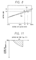
- the outside air introduction mode is set by the inside/outside air selector switch 54 (a ratio of an outside air introduction is 100 %) (at a point A in FIG. 8). Then, when a predetermined amount of frost is deposited on the outdoor heat exchanger 22 and the determination is NO in step 155 shown in FIG. 7, the outside air introduction mode is controlled to become a new inside/outside air select mode in which the ratio of the outside air introduction becomes &A % (at a point B in FIG. 8). That is, at this time, the ratio of the outside air introduction is reduced by (100 - ⁇ ) %.
- the outside air introduction amount is reduced by a predetermined amount while continuing the heating operation. Accordingly, the ventilating air amount Va is reduced. As a result, a frost deposition speed is reduced, and a deposited frost limit is increased like the first embodiment. Accordingly, as shown by the solid lines in FIG. 6, the heating operation time in this embodiment can be made longer than that in the case where the outside air introduction amount is not reduced even when frost is deposited (as shown by the dotted chain lines in FIG. 6).
- the control in step 166 shown in FIG. 7 is modified so that the inside/outside air select mode determined according to the set position of the inside/outside air selector switch 54 is controlled to become a new inside/outside air select mode in which the outside air introduction amount is reduced by a predetermined amount, and that the blower motor 10 is controlled to reduce the air amount to be supplied into the passenger compartment by a predetermined amount.
- the inside/outside air select mode is set to the outside air introduction mode (the ratio of the outside air introduction is 100 %) and the air amount to be supplied into the passenger compartment is controlled to Va1 (at a point A in FIG. 8).
- the air amount to be supplied into the passenger compartment is controlled to become Va2 (shown by a one-dotted chain line in FIG. 8), and the inside/outside air select mode is controlled to become a new inside/outside air select mode in which the ratio of the outside air introduction becomes ⁇ % (at a point C in FIG. 8).
- the outside air introduction amount is reduced by a predetermined amount and the air amount to be supplied into the passenger compartment is also reduced by a predetermined amount as continuing the heating operation.
- the heating operation time can be increased as shown by the solid lines in FIG. 6.
- the frost deposition may be determined by the comparison between a change rate of the suction pressure Ps and a predetermined reference value, the comparison between a refrigerant temperature THO in the outdoor heat exchanger 22 and a predetermined reference value, the comparison between a change rate of the refrigerant temperature THO and a predetermined reference value, the comparison between a sucked refrigerant temperature Ts in the compressor 21 and a predetermined reference value, and the comparison between a change rate of the sucked refrigerant temperature Ts and a predetermined reference value.
- the frost deposition may be determined according to the conditions on the higher-pressure side of the refrigeration cycle 20 in consideration of the fact that a change in the conditions on the lower-pressure side is followed by a change in the conditions on the higher-pressure side.
- the frost deposition may be determined by the comparison between a higher pressure Pd and a predetermined reference value, the comparison between a change rate of the higher pressure Pd and a predetermined reference value, the comparison between an air temperature Tc from the heating indoor heat exchanger 12 and a predetermined reference value, and the comparison between a change rate of the air temperature Tc and a predetermined reference value.
- the frost deposition may be determined by determining whether or not the conditions that frost may be deposited on the outdoor heat exchanger 22 have been satisfied. That is, in the case that the general configuration is the same as that in the first embodiment, the process by the microcomputer is modified to that shown in FIG. 9 (the sixth embodiment). Further, in the case that the general configuration is the same as that in the second preferred embodiment, the process by the microcomputer is modified to that shown in FIG. 10 (the seventh embodiment).
- step 156 it is determined whether or not the conditions that frost may be deposited on the outdoor heat exchanger 22 have been satisfied. If the conditions have been satisfied, step 165 or 166 is performed. More specifically, an outside air humidity sensor for detecting an outside air humidity and an outside air temperature sensor for detecting an outside air temperature are provided. In step 156, it is determined whether or not a detected value Ram from the outside air humidity sensor and a detected value Tam from the outside air temperature sensor satisfy the conditions that frost may be deposited (e.g., a hatched region shown in FIG. 11).
- a ventilating air amount is controlled to be reduced while continuing a heating operation.
- the time for running the vehicle becomes relatively long and the heating operation time is increased, there is a possibility that the deposited frost amount on the outdoor heat exchanger 22 may reach the deposited frost limit.
- a defrosting operation for the outdoor heat exchanger 22 is performed in the same way as the conventional defrosting operation. That is, according to this embodiment, for at least a predetermined period from the time when the frost deposition is determined to the time when the deposited frost amount reaches the deposited frost limit, the ventilating air amount is controlled to be reduced while continuing the heating operation. After this predetermined period has elapsed, the defrosting operation is performed. Accordingly, as compared with the conventional method such that the defrosting operation is performed immediately after the frost deposition has determined, the time period during which the heating operation is continued can be prolonged much longer according to this embodiment.
- the ventilating air amount is controlled to be reduced while continuing the heating operation for at least a predetermined period of time.
- the method of reducing the ventilating air amount may be replaced by a method of reducing an air amount supplied by the fan 9 in the inside air circulation mode.
- a radiated heat amount in the indoor heat exchanger 12 is reduced. Therefore, a higher pressure in the refrigeration cycle 20 is increased, and a lower pressure in the refrigeration cycle 20 is also accordingly increased.
- the increase in the lower pressure causes a rise in temperature of the outdoor heat exchanger 22 functioning as an evaporator during a heating operation. As a result, the frost deposition speed on the outdoor heat exchanger 22 is reduced, and the deposited frost limit is accordingly increased.
- the time period until the deposited frost amount in the outdoor heat exchanger 22 reaches the deposited frost limit can be increased. That is, like each embodiment mentioned above, the time period during which the heating operation is continued can be increased.
- the predetermined time period is defined as a period from the time when frost deposition is determined to the time when the deposited frost amount reaches the deposited frost limit amount in the eighth and ninth embodiments, the predetermined time period defined in the present invention is not limited thereto.
- a step for determining whether or not the outside air temperature is lower than or equal to the predetermined low temperature may be performed. In this case, when it is determined in this step that the outside air temperature is lower than or equal to the predetermined low temperature, the control in the frost deposited condition (step 165 in FIG. 4 or step 166 in FIG. 7) is not performed.
- the first embodiment employs the two inside/outside air select modes, i.e., the outside air introduction mode where the inside/outside air selector door 7 fully closes the inside air inlet 5 and fully opens the outside air inlet 6, and the inside air circulation mode where the inside/outside air selector door 7 fully opens the inside air inlet 5 and fully closes the outside air inlet 6, three or more inside/outside air select modes may be provided, or an inside/outside air select mode may be linearly controlled.
- the determination in step 160 may be performed by determining whether or not the inside/outside air select mode selected is the outside air introduction mode, or by determining whether or not the inside/outside air select mode selected is a mode where the inside/outside air selector door 7 opens the outside air inlet 6 in a predetermined amount.
- the present invention may be applied also to an air conditioner for an engine-driven vehicle.
Landscapes
- Physics & Mathematics (AREA)
- Thermal Sciences (AREA)
- Engineering & Computer Science (AREA)
- Mechanical Engineering (AREA)
- Air-Conditioning For Vehicles (AREA)
Claims (10)
- Climatiseur pour un véhicule ayant un compartiment passager, comprenant :une conduite d'air destinée à former un passaga d'air (2) dans lequel une entrée d'air (5,6) est formée au niveau d'une extrémité de celle-ci et une sortie d'air (14 à 16) communiquant avec ledit compartiment passager est formée au niveau de l'autre extrémité ;un moyen de soufflage (4) destiné à souffler un écoulement d'air provenant de ladite entrée d'air (5,6) vers ladite sortie d'air (14 à 16) ; etun cycle de réfrigération (20) incluant un compresseur (21) pour comprimer un réfrigérant, un échangeur de chaleur intérieur (12) disposé dans ledit passage d'air (2), un moyen de réduction de pression (24) pour réduire une pression dudit réfrigérant, et un échangeur de chaleur extérieur (22) disposé à l'extérieur dudit compartiment passager, ledit échangeur de chaleur intérieur (12) et ledit échangeur de chaleur extérieur (22) fonctionnant comme un condenseur et un évaporateur dans une opération de chauffage, respectivement ;un moyen de détermination de déposition de givre (155) destiné à déterminer si oui ou non une quantité prédéterminée de givre s'est déposée sur ledit échangeur de chaleur extérieur (22) dans ladite opération de chauffage ; etun moyen de commande (160, 165, 166) pour commander une quantité de chaleur rayonnée dans ledit échangeur de chaleur intérieur (12), lorsque ledit moyen de détermination de déposition de givre (155) détermine que ladite quantité prédéterminée de givre s'est déposée ou a pu se déposer sur ledit échangeur de chaleur extérieur (22), de manière telle que ledit moyen de commande (160,165,166) réduit ladite quantité de chaleur rayonnée pendant au moins une période prédéterminée d'une quantité de chaleur rayonnée dans ledit échangeur de chaleur intérieur (12) avant que ladite quantité prédéterminée de déposition de givre ait été déterminée par ledit moyen de détermination de déposition de givre (155) tout en maintenant ledit échangeur de chaleur intérieur (12) et ledit échangeur de chaleur extérieur (12) fonctionnant en tant que ledit évaporateur et ledit condenseur, respectivement.
- Climatiseur selon la revendication 1, dans lequel ladite entrée d'air (5,6) inclut une entrée d'air intérieur (5) et une entrée d'air extérieur (6).
- Climatiseur selon la revendication 2, comprenant, en outre :dans lequel ledit moyen de commande (160,165,166) inclut :un moyen d'ouverture/fermeture d'entrée d'air (7) pour ouvrir et fermer sélectivement ladite entrée d'air intérieur (5) et ladite entrée d'air extérieur (6) ;un moyen de détermination d'entrée d'air (160) destiné à déterminer si oui ou non ledit moyen d'ouverture/fermeture d'entrée d'air (7) a ouvert ladite entrée d'air extérieur (6) ; etun moyen de commande de réduction de quantité d'air (165) destiné à réduire une quantité d'air par ledit moyen de soufflage (4) lorsque ledit moyen de détermination d'entrée d'air (160) détermine que ladite entrée d'air extérieur (6) est ouverte, à partir d'une quantité d'air avant que ladite quantité prédéterminée de déposition de givre ait été déterminée par ledit moyen de détermination de déposition de givre (155).
- Climatiseur selon la revendication 2, comprenant, en outre :dans lequel ledit moyen de commande (160,165,166) inclut :un moyen d'ouverture/fermeture d'entrée d'air (7) destiné à ouvrir et fermer sélectivement ladite entrée d'air intérieur (5) et ladite entrée d'air extérieur (6) ;un moyen de commande d'entrée d'air (160) destiné à commander ledit moyen d'ouverture/fermeture d'entrée (7) de manière à réduire un rapport d'une introduction d'air extérieur dans laquelle ladite entrée d'air extérieur (6) est ouverte par ledit moyen d'ouverture/fermeture d'entrée d'air (7), à partir d'un rapport de ladite introduction d'air extérieur avant que ladite quantité prédéterminée de déposition de givre ait été déterminée par ledit moyen de détermination de déposition de givre.
- Climatiseur selon la revendication 1, comprenant, en outre :dans lequel ledit moyen de détermination de déposition de givre (155) détermine si oui ou non ladite quantité prédéterminée de givre a été déposée sur ledit échangeur de chaleur extérieur (22) en conformité avec lesdites conditions détectées par ledit moyen de détermination de conditions côté pression inférieure (42).un moyen de détection de conditions côté pression inférieure (42) destiné à détecter des conditions sur un côté pression inférieure dudit cycle de réfrigération (20) ;
- Climatiseur selon la revendication 1, comprenant, en outre :dans lequel ledit moyen de détermination de déposition de givre (155) détermine si oui ou non ladite quantité prédéterminée de givre a été déposée sur ledit échangeur de chaleur extérieur (22) en conformité avec lesdites conditions détectées par ledit moyen de détection de conditions côté pression supérieure.un moyen de détection de condition côté pression supérieure destiné à détecter des conditions sur un côté pression supérieure dudit cycle de réfrigération ;
- Climatiseur pour un véhicule selon la revendication 1,
dans lequel ledit véhicule est un véhicule électrique. - Climatiseur selon la revendication 1, comprenant, en outre :dans lequel ledit moyen de détermination de conditions de déposition de givre (156) détermine si oui ou non lesdites conditions pour que du givre puisse se déposer sur ledit échangeur de chaleur extérieur (22) ont été satisfaites en conformité avec ladite humidité d'air extérieur détectée par ledit moyen de détection d'humidité d'air extérieur et ladite température d'air extérieur détectée par ledit moyen de détection de température d'air extérieur.un moyen de détection d'humidité d'air extérieur destiné à détecter une humidité d'air extérieur ; etun moyen de détection de température d'air extérieur destiné à détecter une température d'air extérieur ;
- Climatiseur selon la revendication 1, dans lequel ledit moyen de commande (160,165,166) réduit la quantité de chaleur rayonnée dans ledit échangeur de chaleur intérieur en réduisant pendant au moins une période prédéterminée la quantité d'air de ventilation qui est aspirée à partir de ladite entrée d'air (5,6) et soufflée dans ledit compartiment passager à travers ladite sortie d'air (14 à 16) par ledit moyen de soufflage lorsque ledit moyen de détermination de déposition de givre (155) détermine que ladite quantité prédéterminée de givre a été ou a pu se déposer sur ledit échangeur de chaleur extérieur (22) tout en maintenant ladite opération de chauffage.
- Climatiseur selon la revendication 1 ou 2, dans lequel le moyen de commande (160,165,166) commande une quantité d'air de ventilation qui est aspirée à partir de ladite entrée d'air extérieur (6) et soufflée dans ledit compartiment passager à travers ladite sortie d'air (14 à 16) par ledit moyen de soufflage (4), lorsque ledit moyen de détermination de déposition de givre (155) détermine que ladite quantité prédéterminée de givre s'est déposée sur ledit échangeur de chaleur extérieur (22) de manière telle que ledit moyen de commande (160, 165, 166) réduit ladite quantité d'air de ventilation pendant au moins une période prédéterminée d'une quantité d'air de ventilation avant que ladite quantité prédéterminée de déposition de givre ait été déterminée par ledit moyen de détermination de déposition de givre (155) tout en maintenant ledit échanseur de chaleur intérieur (12) et ledit échangeur de chaleur extérieur (22) fonctionnant comme ledit évaporateur et ledit condenseur, respectivement.
Applications Claiming Priority (6)
| Application Number | Priority Date | Filing Date | Title |
|---|---|---|---|
| JP24479795 | 1995-09-22 | ||
| JP24479795 | 1995-09-22 | ||
| JP244797/95 | 1995-09-22 | ||
| JP18249896 | 1996-07-11 | ||
| JP8182498A JPH09142139A (ja) | 1995-09-22 | 1996-07-11 | 車両用空調装置 |
| JP182498/96 | 1996-07-11 |
Publications (3)
| Publication Number | Publication Date |
|---|---|
| EP0788910A2 EP0788910A2 (fr) | 1997-08-13 |
| EP0788910A3 EP0788910A3 (fr) | 1999-01-07 |
| EP0788910B1 true EP0788910B1 (fr) | 2003-08-27 |
Family
ID=26501283
Family Applications (1)
| Application Number | Title | Priority Date | Filing Date |
|---|---|---|---|
| EP96115036A Expired - Lifetime EP0788910B1 (fr) | 1995-09-22 | 1996-09-19 | Dispositif de climatisation pour véhicule avec améliorations empêchant la formation de givre |
Country Status (4)
| Country | Link |
|---|---|
| US (1) | US5704217A (fr) |
| EP (1) | EP0788910B1 (fr) |
| JP (1) | JPH09142139A (fr) |
| DE (1) | DE69629659T2 (fr) |
Cited By (1)
| Publication number | Priority date | Publication date | Assignee | Title |
|---|---|---|---|---|
| DE102021206455A1 (de) | 2021-06-23 | 2022-12-29 | Volkswagen Aktiengesellschaft | Verfahren zum Einleiten eines Abtauprozesses eines Wärmeübertragers einer Wärmepumpe eines Kraftfahrzeuges |
Families Citing this family (36)
| Publication number | Priority date | Publication date | Assignee | Title |
|---|---|---|---|---|
| JP4380077B2 (ja) | 2000-09-27 | 2009-12-09 | 株式会社デンソー | 車両用空調装置 |
| JP2002285958A (ja) * | 2001-03-28 | 2002-10-03 | Matsushita Refrig Co Ltd | リニアコンプレッサの制御装置 |
| JP2002286276A (ja) * | 2001-03-28 | 2002-10-03 | Mitsubishi Electric Corp | 空気調和装置および制御方法 |
| DE50308277D1 (de) | 2002-01-14 | 2007-11-08 | Behr Gmbh & Co Kg | Heiz-/kühlkreislauf für eine klimaanlage eines kraftfahrzeugs, klimaanlage und verfahren zur steuerung derselben |
| US6955057B2 (en) * | 2003-06-30 | 2005-10-18 | Carrier Corporation | Control scheme and method for dehumidification systems at low ambient conditions |
| US20070251251A1 (en) * | 2006-04-26 | 2007-11-01 | Valeo Climate Control Corp. | HVAC heat exchanger freeze control means |
| US8910705B2 (en) * | 2008-05-27 | 2014-12-16 | Toyota Motor Engineering & Manufacturing North America, Inc. | Radiator fan control for heat pump HVAC |
| DE102010025779A1 (de) | 2009-07-03 | 2011-01-13 | DENSO CORPORATION, Kariya-shi | Klimatisierungsvorrichtung für Fahrzeug und Verfahren zu deren Steuerung |
| JP5446520B2 (ja) * | 2009-07-03 | 2014-03-19 | 株式会社デンソー | 車両用空調装置の制御方法 |
| CN102472540B (zh) * | 2009-07-22 | 2014-07-02 | 三菱电机株式会社 | 热泵装置 |
| EP2347921A1 (fr) * | 2010-01-26 | 2011-07-27 | Ford Global Technologies, LLC | Climatisation manuelle d'un véhicule automobile |
| JP5468982B2 (ja) * | 2010-05-14 | 2014-04-09 | カルソニックカンセイ株式会社 | 車両用空気調和装置 |
| JP5474024B2 (ja) * | 2011-10-27 | 2014-04-16 | 三菱電機株式会社 | 冷凍サイクル装置 |
| JP2014019179A (ja) * | 2012-07-12 | 2014-02-03 | Japan Climate Systems Corp | 車両用空調装置 |
| KR101430005B1 (ko) * | 2012-03-05 | 2014-08-19 | 한라비스테온공조 주식회사 | 차량용 히트 펌프 시스템 및 그 제어방법 |
| KR101418854B1 (ko) * | 2012-03-05 | 2014-08-14 | 한라비스테온공조 주식회사 | 차량용 히트 펌프 시스템 |
| CN104813119B (zh) * | 2012-07-31 | 2017-05-17 | 开利公司 | 冻结蒸发器盘管检测以及除霜起始 |
| JP6024305B2 (ja) * | 2012-09-05 | 2016-11-16 | 株式会社デンソー | 車両用空調装置 |
| CN107878148B (zh) | 2012-09-19 | 2021-02-12 | 日产自动车株式会社 | 冷暖空调装置 |
| DE102012219168B4 (de) * | 2012-10-22 | 2021-10-14 | Bayerische Motoren Werke Aktiengesellschaft | Verfahren zum Steuern des Kältemitteldrucks in einem Umgebungswärmetauscher eines Kältemittelkreislaufs |
| JP6047388B2 (ja) * | 2012-11-30 | 2016-12-21 | サンデンホールディングス株式会社 | 車両用空気調和装置 |
| US9796243B2 (en) * | 2013-02-05 | 2017-10-24 | Ford Global Technologies, Llc | Coolest A/C discharge temperature for all operating conditions |
| WO2014174623A1 (fr) * | 2013-04-24 | 2014-10-30 | 三菱電機株式会社 | Dispositif de déshumidification |
| WO2014174622A1 (fr) * | 2013-04-24 | 2014-10-30 | 三菱電機株式会社 | Dispositif de déshumidification |
| JP6204111B2 (ja) * | 2013-08-09 | 2017-09-27 | 株式会社日本クライメイトシステムズ | 車両用空調装置 |
| JP6192435B2 (ja) * | 2013-08-23 | 2017-09-06 | サンデンホールディングス株式会社 | 車両用空気調和装置 |
| JP6192434B2 (ja) * | 2013-08-23 | 2017-09-06 | サンデンホールディングス株式会社 | 車両用空気調和装置 |
| US10222108B2 (en) * | 2014-03-28 | 2019-03-05 | Hitachi-Johnson Controls Air Conditioning, Inc. | Air conditioner |
| JP6418779B2 (ja) | 2014-05-08 | 2018-11-07 | サンデンホールディングス株式会社 | 車両用空気調和装置 |
| JP6499441B2 (ja) * | 2014-12-24 | 2019-04-10 | カルソニックカンセイ株式会社 | 車両用空調装置 |
| JP5999171B2 (ja) * | 2014-12-26 | 2016-09-28 | ダイキン工業株式会社 | 空気調和装置 |
| JP6332193B2 (ja) * | 2015-08-06 | 2018-05-30 | 株式会社デンソー | 車両用空調装置 |
| CN106004323B (zh) * | 2016-05-25 | 2019-04-09 | 珠海格力电器股份有限公司 | 一种电动汽车空调系统及应用其的电动汽车 |
| CN106476565B (zh) * | 2016-10-25 | 2019-03-26 | 珠海格力电器股份有限公司 | 一种热泵空调机组、其控制方法及电动客车 |
| DE102016225723A1 (de) * | 2016-12-21 | 2018-06-21 | Bayerische Motoren Werke Aktiengesellschaft | Verfahren und Steuereinheit zur Steuerung einer Klimaanlage |
| JP2024076504A (ja) * | 2022-11-25 | 2024-06-06 | サンデン株式会社 | 車両用空調装置 |
Family Cites Families (10)
| Publication number | Priority date | Publication date | Assignee | Title |
|---|---|---|---|---|
| US4102391A (en) * | 1977-03-10 | 1978-07-25 | General Electric Company | Heat pump frost control system |
| US4257795A (en) * | 1978-04-06 | 1981-03-24 | Dunham-Bush, Inc. | Compressor heat pump system with maximum and minimum evaporator ΔT control |
| SE418829B (sv) * | 1979-11-12 | 1981-06-29 | Volvo Ab | Anordning vid luftkonditioneringsaggregat for motorfordon |
| US5170635A (en) * | 1990-05-21 | 1992-12-15 | Honeywell Inc. | Defrost for air handling system utilizing direct expansion cooling |
| JP2831838B2 (ja) * | 1990-11-06 | 1998-12-02 | 株式会社東芝 | 空気調和機 |
| JPH04278153A (ja) * | 1991-03-06 | 1992-10-02 | Toshiba Corp | 冷暖房装置 |
| JPH0577636A (ja) * | 1991-09-19 | 1993-03-30 | Zexel Corp | ヒートポンプ式自動車用空調装置 |
| JP2979802B2 (ja) * | 1991-12-27 | 1999-11-15 | 株式会社デンソー | 空気調和装置 |
| JP3463303B2 (ja) * | 1991-12-27 | 2003-11-05 | 日産自動車株式会社 | 車両用ヒートポンプ式冷暖房装置 |
| EP0678409B1 (fr) * | 1994-04-21 | 1998-08-05 | Denso Corporation | Appareil de conditionnement d'air |
-
1996
- 1996-07-11 JP JP8182498A patent/JPH09142139A/ja active Pending
- 1996-09-19 EP EP96115036A patent/EP0788910B1/fr not_active Expired - Lifetime
- 1996-09-19 DE DE69629659T patent/DE69629659T2/de not_active Expired - Fee Related
- 1996-09-19 US US08/715,965 patent/US5704217A/en not_active Expired - Fee Related
Cited By (1)
| Publication number | Priority date | Publication date | Assignee | Title |
|---|---|---|---|---|
| DE102021206455A1 (de) | 2021-06-23 | 2022-12-29 | Volkswagen Aktiengesellschaft | Verfahren zum Einleiten eines Abtauprozesses eines Wärmeübertragers einer Wärmepumpe eines Kraftfahrzeuges |
Also Published As
| Publication number | Publication date |
|---|---|
| EP0788910A3 (fr) | 1999-01-07 |
| DE69629659D1 (de) | 2003-10-02 |
| EP0788910A2 (fr) | 1997-08-13 |
| JPH09142139A (ja) | 1997-06-03 |
| DE69629659T2 (de) | 2004-06-17 |
| US5704217A (en) | 1998-01-06 |
Similar Documents
| Publication | Publication Date | Title |
|---|---|---|
| EP0788910B1 (fr) | Dispositif de climatisation pour véhicule avec améliorations empêchant la formation de givre | |
| US7121103B2 (en) | Vehicle air conditioning system | |
| US6523361B2 (en) | Air conditioning systems | |
| US6898946B2 (en) | Vehicle air-conditioning system | |
| US5632156A (en) | Automotive air conditioning system | |
| US5669231A (en) | Air conditioning apparatus | |
| US20020104324A1 (en) | Air conditioner for hybrid vehicle | |
| US6266967B1 (en) | Refrigerant cycle system for vehicle air conditioner | |
| US5499511A (en) | Heat pump type air conditioner for vehicle | |
| US7082990B1 (en) | Air conditioning apparatus for vehicle | |
| US5769316A (en) | Air conditioner for vehicles | |
| US5709098A (en) | Air conditioning apparatus | |
| US5778691A (en) | Gas injection type heat pump apparatus | |
| JPH058631A (ja) | 車両用空調装置 | |
| US6003325A (en) | Air conditioner particularly suitable for vehicle and method of controlling the same | |
| JP2000283611A (ja) | ヒートポンプ式空調装置 | |
| GB2396689A (en) | Vehicle air conditioner having refrigerant cycle with hot gas bypass heating function | |
| JP4626470B2 (ja) | 車両用空調装置 | |
| JPH10119560A (ja) | 空調装置 | |
| JPH10115448A (ja) | 空調装置 | |
| JP2000291995A (ja) | 空調装置 | |
| JPH06183245A (ja) | 電気自動車用空気調和装置の制御装置 | |
| JPH06191253A (ja) | 車両用空気調和装置 | |
| JP2654691B2 (ja) | 自動車用空調制御装置 | |
| JP2000219023A (ja) | 車両用空調装置 |
Legal Events
| Date | Code | Title | Description |
|---|---|---|---|
| PUAI | Public reference made under article 153(3) epc to a published international application that has entered the european phase |
Free format text: ORIGINAL CODE: 0009012 |
|
| AK | Designated contracting states |
Kind code of ref document: A2 Designated state(s): DE FR IT |
|
| PUAL | Search report despatched |
Free format text: ORIGINAL CODE: 0009013 |
|
| AK | Designated contracting states |
Kind code of ref document: A3 Designated state(s): DE FR IT |
|
| 17P | Request for examination filed |
Effective date: 19990319 |
|
| 17Q | First examination report despatched |
Effective date: 20020627 |
|
| GRAH | Despatch of communication of intention to grant a patent |
Free format text: ORIGINAL CODE: EPIDOS IGRA |
|
| GRAS | Grant fee paid |
Free format text: ORIGINAL CODE: EPIDOSNIGR3 |
|
| GRAA | (expected) grant |
Free format text: ORIGINAL CODE: 0009210 |
|
| AK | Designated contracting states |
Designated state(s): DE FR IT |
|
| PGFP | Annual fee paid to national office [announced via postgrant information from national office to epo] |
Ref country code: FR Payment date: 20030909 Year of fee payment: 8 |
|
| PGFP | Annual fee paid to national office [announced via postgrant information from national office to epo] |
Ref country code: DE Payment date: 20031002 Year of fee payment: 8 |
|
| REF | Corresponds to: |
Ref document number: 69629659 Country of ref document: DE Date of ref document: 20031002 Kind code of ref document: P |
|
| ET | Fr: translation filed | ||
| PLBE | No opposition filed within time limit |
Free format text: ORIGINAL CODE: 0009261 |
|
| STAA | Information on the status of an ep patent application or granted ep patent |
Free format text: STATUS: NO OPPOSITION FILED WITHIN TIME LIMIT |
|
| 26N | No opposition filed |
Effective date: 20040528 |
|
| PG25 | Lapsed in a contracting state [announced via postgrant information from national office to epo] |
Ref country code: DE Free format text: LAPSE BECAUSE OF NON-PAYMENT OF DUE FEES Effective date: 20050401 |
|
| PG25 | Lapsed in a contracting state [announced via postgrant information from national office to epo] |
Ref country code: FR Free format text: LAPSE BECAUSE OF NON-PAYMENT OF DUE FEES Effective date: 20050531 |
|
| REG | Reference to a national code |
Ref country code: FR Ref legal event code: ST |
|
| PG25 | Lapsed in a contracting state [announced via postgrant information from national office to epo] |
Ref country code: IT Free format text: LAPSE BECAUSE OF NON-PAYMENT OF DUE FEES Effective date: 20050919 |