EP0749861A2 - Disque d'entraînement entre un moteur alternatif à combustion interne et un convertisseur de couple - Google Patents
Disque d'entraînement entre un moteur alternatif à combustion interne et un convertisseur de couple Download PDFInfo
- Publication number
- EP0749861A2 EP0749861A2 EP96105386A EP96105386A EP0749861A2 EP 0749861 A2 EP0749861 A2 EP 0749861A2 EP 96105386 A EP96105386 A EP 96105386A EP 96105386 A EP96105386 A EP 96105386A EP 0749861 A2 EP0749861 A2 EP 0749861A2
- Authority
- EP
- European Patent Office
- Prior art keywords
- flange
- driving plate
- internal combustion
- combustion engine
- converter
- Prior art date
- Legal status (The legal status is an assumption and is not a legal conclusion. Google has not performed a legal analysis and makes no representation as to the accuracy of the status listed.)
- Ceased
Links
Images
Classifications
-
- B—PERFORMING OPERATIONS; TRANSPORTING
- B60—VEHICLES IN GENERAL
- B60K—ARRANGEMENT OR MOUNTING OF PROPULSION UNITS OR OF TRANSMISSIONS IN VEHICLES; ARRANGEMENT OR MOUNTING OF PLURAL DIVERSE PRIME-MOVERS IN VEHICLES; AUXILIARY DRIVES FOR VEHICLES; INSTRUMENTATION OR DASHBOARDS FOR VEHICLES; ARRANGEMENTS IN CONNECTION WITH COOLING, AIR INTAKE, GAS EXHAUST OR FUEL SUPPLY OF PROPULSION UNITS IN VEHICLES
- B60K17/00—Arrangement or mounting of transmissions in vehicles
- B60K17/02—Arrangement or mounting of transmissions in vehicles characterised by arrangement, location, or kind of clutch
-
- F—MECHANICAL ENGINEERING; LIGHTING; HEATING; WEAPONS; BLASTING
- F16—ENGINEERING ELEMENTS AND UNITS; GENERAL MEASURES FOR PRODUCING AND MAINTAINING EFFECTIVE FUNCTIONING OF MACHINES OR INSTALLATIONS; THERMAL INSULATION IN GENERAL
- F16H—GEARING
- F16H41/00—Rotary fluid gearing of the hydrokinetic type
- F16H41/24—Details
Definitions
- the invention relates to a drive plate between an internal combustion engine of the reciprocating piston type and a converter according to the preamble of patent claim 1.
- the object of the invention is therefore to provide a connection of a drive plate of an internal combustion engine with a converter, which enables sophisticated compact arrangements of such engine units with good accessibility.
- the converter can be brought particularly close to the internal combustion engine.
- the fastening screws are easily accessible for assembly purposes.
- the arrangement of the starter ring and the sensor ring also has a favorable spatial effect. Possible tolerances between centering device and flange in the area the fastening screws are compensated for by the elastic design. It can be realized in a simple manner by means of suitable recesses in the flange which, depending on the design, can be compared with solutions of the construction principle "carrying out hub-shaft connections with axial screw connections".
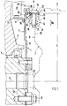
- An internal combustion engine 1 is connected to a converter 2 of a transmission 3, not shown in detail.
- the converter 2 is brought very close to the internal combustion engine 1.
- the internal combustion engine 1 comprises a crankcase 4 with a crankshaft 5 which has a central longitudinal axis 6. With the crankshaft 5 is a driving plate 7, which is held in place by screws 8 on the crankshaft 5.
- the driving disk 7 comprises an upright disk part 9 and a flange 10.
- the disk part 9 has a sensor ring 11 on the side facing the internal combustion engine 1, which cooperates with a cylindrical sensor 12 arranged inside the crankcase 4 and oriented radially to the crankshaft 5 .
- the sensor ring 11 is designed as an angle and engages under the sensor 12 with its free end 13, which faces away from the disk part 9 in the direction of the crankcase 4.
- the flange 10 runs at a parallel distance C to the central longitudinal plane 6 and has the free end 13 facing the transducer 2.
- the transducer 2 is provided with an essentially upright but profiled housing wall 14 which is brought as close as possible to the disk part 9 with a first wall section 15 which is enlarged in the axial direction.
- a second wall section 16 set back in the diameter of the transducer and lying outside the first wall section 15 in the axial direction with respect to the first wall section 15, a plurality of receptacles 17 are fixedly attached to the circumference and are overlapped by the flange 10.
- Each receptacle 17 comprises a threaded bore 18 into which a fastening screw 19 which clamps the flange 10 against the receptacle 17 is screwed; Threaded bore 18 and fastening screw 19 are aligned radially to crankshaft 5.
- the fastening screw 19 has a threaded pin 21 penetrating a bore 20 in the flange 10 and a screw head 22, a starter collar 23 being fixed on the flange 10 between the screw head 22 and the crankcase 4.
- the flange 10 is formed elastically locally in a fastening area 24 of the fastening screw 19 in the radial direction Ra.
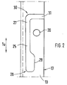
- a recess 25 is provided in the flange 10, which is arranged between a flange part 26 and the disk part 9.
- the recess 25 is designed over a partial circumference Tu of the flange 10 as a slot 27, ie the slot 27 extends — seen in the circumferential direction of the flange 10 — on both sides of the bore 20 in the flange part 26.
- the slot 27 is at least on one First end side 28 is provided with an extension 29 or it can be guided on a second end side 30 in the direction of the free end 13 and have a through opening 31.
- the converter 2 is provided with a centering pin 32, which extends along the central longitudinal axis 6 and cooperates with a centering hole 33 of the internal combustion engine 1 to fix the position.
- the centering opening 33 is provided in the crankshaft 4 in the exemplary embodiment.
- Concentric to Centering pin 32 is formed a support surface 34 of the receptacle 17 designed as a local support 35; The flange 10 rests on the support surface 34.
Landscapes
- Engineering & Computer Science (AREA)
- Mechanical Engineering (AREA)
- General Engineering & Computer Science (AREA)
- Chemical & Material Sciences (AREA)
- Combustion & Propulsion (AREA)
- Transportation (AREA)
- Cylinder Crankcases Of Internal Combustion Engines (AREA)
- Arrangement Of Transmissions (AREA)
Applications Claiming Priority (2)
| Application Number | Priority Date | Filing Date | Title |
|---|---|---|---|
| DE1995122869 DE19522869A1 (de) | 1995-06-23 | 1995-06-23 | Mitnehmerscheibe zwischen einer Brennkraftmaschine der Hubkolbenbauart und einem Wandler |
| DE19522869 | 1995-06-23 |
Publications (2)
| Publication Number | Publication Date |
|---|---|
| EP0749861A2 true EP0749861A2 (fr) | 1996-12-27 |
| EP0749861A3 EP0749861A3 (fr) | 1997-12-29 |
Family
ID=7765104
Family Applications (1)
| Application Number | Title | Priority Date | Filing Date |
|---|---|---|---|
| EP96105386A Ceased EP0749861A3 (fr) | 1995-06-23 | 1996-04-04 | Disque d'entraínement entre un moteur alternatif à combustion interne et un convertisseur de couple |
Country Status (3)
| Country | Link |
|---|---|
| EP (1) | EP0749861A3 (fr) |
| JP (1) | JPH0914387A (fr) |
| DE (1) | DE19522869A1 (fr) |
Cited By (7)
| Publication number | Priority date | Publication date | Assignee | Title |
|---|---|---|---|---|
| WO2001055621A3 (fr) * | 2000-01-29 | 2002-03-07 | Zahnradfabrik Friedrichshafen | Plateau d'entrainement pour le transfert de couple d'une unite d'entrainement a un convertisseur hydrodynamique |
| EP1190882A1 (fr) * | 2000-09-22 | 2002-03-27 | Siemens Aktiengesellschaft | Dispositif d'entraínement pour un véhicule |
| GB2345332B (en) * | 1998-12-28 | 2003-09-17 | Luk Lamellen & Kupplungsbau | Torque transfer device |
| EP1347210A1 (fr) * | 2002-03-19 | 2003-09-24 | DaimlerChrysler AG | Assemblage vissé entre un élément à transmission de couple et une coque d'un aggregat d'un groupe d'entraínement d'un véhicule |
| EP1389825A3 (fr) * | 2002-08-07 | 2007-06-13 | Siemens Aktiengesellschaft | Agencement d'un moteur de traction pour un véhicule |
| DE102008023584A1 (de) | 2008-05-14 | 2009-01-22 | Daimler Ag | Mitnehmerscheibe |
| FR2936577A1 (fr) * | 2008-09-29 | 2010-04-02 | Renault Sas | Dispositif d'entrainement de convertisseur de couple et procede de fixation d'une couronne de demarreur sur un plateau cible de convertisseur de couple |
Families Citing this family (9)
| Publication number | Priority date | Publication date | Assignee | Title |
|---|---|---|---|---|
| DE19747965A1 (de) * | 1997-10-30 | 1999-05-12 | Bayerische Motoren Werke Ag | Drehmomentwandleranbindung mit Magnetkraft |
| US6604885B1 (en) | 1997-10-30 | 2003-08-12 | Bayerische Motoren Werke Aktiengesellschaft | Torque transmitter connection assembly |
| DE19747962A1 (de) * | 1997-10-30 | 1999-05-12 | Bayerische Motoren Werke Ag | Drehmomentwandleranbindung |
| DE19747964A1 (de) * | 1997-10-30 | 1999-05-12 | Bayerische Motoren Werke Ag | Anbindung für einen Drehmomentwandler |
| DE19818412C2 (de) * | 1998-04-24 | 2001-05-17 | Mannesmann Sachs Ag | Kupplungseinrichtung zur Anbindung einer Schwungmasse an einen Antrieb |
| DE102004050772A1 (de) * | 2004-10-19 | 2006-04-20 | Daimlerchrysler Ag | Mitnehmerscheibe |
| JP4927760B2 (ja) | 2005-05-09 | 2012-05-09 | ダイキン工業株式会社 | フルオロシリコーンおよび含フッ素含ケイ素表面処理剤 |
| JP4785573B2 (ja) * | 2006-03-15 | 2011-10-05 | ダイハツ工業株式会社 | ドライブプレートの締結構造 |
| DE102009048688A1 (de) * | 2009-10-07 | 2011-04-14 | Audi Ag | Verbindungsanordnung |
Family Cites Families (4)
| Publication number | Priority date | Publication date | Assignee | Title |
|---|---|---|---|---|
| DE1898250U (de) * | 1964-05-12 | 1964-08-06 | Fichtel & Sachs Ag | Elastischer ausgleichskoerper zur befestigung einer hydrodynamischen kraftuebertragungseinrichtung, insbesondere eines hydrodynamischen drehmomentwandlers an das antriebsaggregat. |
| DE3816114A1 (de) * | 1988-05-11 | 1989-11-23 | Porsche Ag | Abtastvorrichtung zur drehzahlmessung an einer brennkraftmaschine |
| US4997408A (en) * | 1989-11-13 | 1991-03-05 | General Motors Corporation | Axial spline drive lug |
| DE4333644A1 (de) * | 1993-10-02 | 1995-04-06 | Zahnradfabrik Friedrichshafen | Einrichtung zur Moment-Übertragung einer Antriebseinheit auf ein Getriebe mit einem hydrodynamischen Wandler |
-
1995
- 1995-06-23 DE DE1995122869 patent/DE19522869A1/de not_active Withdrawn
-
1996
- 1996-04-04 EP EP96105386A patent/EP0749861A3/fr not_active Ceased
- 1996-06-04 JP JP14199096A patent/JPH0914387A/ja active Pending
Cited By (9)
| Publication number | Priority date | Publication date | Assignee | Title |
|---|---|---|---|---|
| GB2345332B (en) * | 1998-12-28 | 2003-09-17 | Luk Lamellen & Kupplungsbau | Torque transfer device |
| WO2001055621A3 (fr) * | 2000-01-29 | 2002-03-07 | Zahnradfabrik Friedrichshafen | Plateau d'entrainement pour le transfert de couple d'une unite d'entrainement a un convertisseur hydrodynamique |
| US6692362B2 (en) | 2000-01-29 | 2004-02-17 | Zfffriedrichshafen Ag | Driving disc for transmitting the torque from a drive unit to a hydrodynamic converter |
| EP1190882A1 (fr) * | 2000-09-22 | 2002-03-27 | Siemens Aktiengesellschaft | Dispositif d'entraínement pour un véhicule |
| WO2002026513A1 (fr) * | 2000-09-22 | 2002-04-04 | Siemens Aktiengesellschaft | Dispositif d'entrainement, notamment pour un vehicule automobile |
| EP1347210A1 (fr) * | 2002-03-19 | 2003-09-24 | DaimlerChrysler AG | Assemblage vissé entre un élément à transmission de couple et une coque d'un aggregat d'un groupe d'entraínement d'un véhicule |
| EP1389825A3 (fr) * | 2002-08-07 | 2007-06-13 | Siemens Aktiengesellschaft | Agencement d'un moteur de traction pour un véhicule |
| DE102008023584A1 (de) | 2008-05-14 | 2009-01-22 | Daimler Ag | Mitnehmerscheibe |
| FR2936577A1 (fr) * | 2008-09-29 | 2010-04-02 | Renault Sas | Dispositif d'entrainement de convertisseur de couple et procede de fixation d'une couronne de demarreur sur un plateau cible de convertisseur de couple |
Also Published As
| Publication number | Publication date |
|---|---|
| EP0749861A3 (fr) | 1997-12-29 |
| JPH0914387A (ja) | 1997-01-14 |
| DE19522869A1 (de) | 1997-01-02 |
Similar Documents
| Publication | Publication Date | Title |
|---|---|---|
| EP0749861A2 (fr) | Disque d'entraînement entre un moteur alternatif à combustion interne et un convertisseur de couple | |
| DE3890168C2 (de) | Rückstelleinrichtung für eine Drosselklappe eines Verbrennungsmotors | |
| EP0492122B1 (fr) | Système d'admission d'air pour un moteur à combustion interne | |
| WO2001057386A1 (fr) | Unite de refoulement | |
| WO1990013740A1 (fr) | Distributeur de carburant pour les systemes d'injection des moteurs a combustion interne | |
| EP0075659B1 (fr) | Moteur à combustion à quatre cylindres | |
| DE69012376T2 (de) | Kompressorgehäuse mit einer Einrichtung zum Verhindern des Verrutschens von schwingungsisolierenden Teilen. | |
| EP0514646B1 (fr) | Dispositif d'admission pour moteur à combustion interne à plusieurs cylindres | |
| DE3122533A1 (de) | Brennkraftmaschine | |
| DE19535963B4 (de) | System zur Abnahme von Leistung aus einer Kurbelwelle | |
| EP1321692B1 (fr) | Support de moteur | |
| DE60016895T2 (de) | Vorrichtung für brennkraftmaschinen | |
| DE69405925T2 (de) | Vorrichtung zur Kompensation eines Lagefehlers eines Antriebsystems auf einer Brennkraftmaschine | |
| EP1068979A2 (fr) | Pot d'échappement | |
| EP0166109A2 (fr) | Piston à plusieurs parties pour un moteur à combustion interne | |
| DE2547992A1 (de) | Zylinderkopf fuer brennkraftmaschinen mit verdichtungszuendung | |
| DE3819728C2 (de) | Ansaugschalldämpfer | |
| EP0243577A2 (fr) | Vilebrequin en matière ferreuse pour machines à piston | |
| DE3930514A1 (de) | Schiffsantriebsanlage | |
| DE69502511T2 (de) | Zusammenbau einer Kipphebelwelle in einem Zylinderkopf einer Brennkraftmaschine | |
| EP0397791B1 (fr) | Carter de pompe centrifuge | |
| EP0255707B1 (fr) | Agencement d'un appareil auxiliaire par l'assemblage à vis d'un élément de machine hautement chargé, notamment d'un moteur à combustion interne | |
| DE2706021A1 (de) | Verfahren fuer die montierung einer nockenwelle | |
| DE102014009558A1 (de) | Halteanordnung zum schwingungsentkoppelten Befestigen zweier Bauteile | |
| WO2022268258A1 (fr) | Moteur à piston alternatif comprenant un corps de cylindre et un vilebrequin relié à ce dernier |
Legal Events
| Date | Code | Title | Description |
|---|---|---|---|
| PUAI | Public reference made under article 153(3) epc to a published international application that has entered the european phase |
Free format text: ORIGINAL CODE: 0009012 |
|
| AK | Designated contracting states |
Kind code of ref document: A2 Designated state(s): DE FR GB IT |
|
| PUAL | Search report despatched |
Free format text: ORIGINAL CODE: 0009013 |
|
| AK | Designated contracting states |
Kind code of ref document: A3 Designated state(s): DE FR GB IT |
|
| 17P | Request for examination filed |
Effective date: 19980603 |
|
| 17Q | First examination report despatched |
Effective date: 19991109 |
|
| STAA | Information on the status of an ep patent application or granted ep patent |
Free format text: STATUS: THE APPLICATION HAS BEEN REFUSED |
|
| 18R | Application refused |
Effective date: 20000324 |