EP0075659B1 - Moteur à combustion à quatre cylindres - Google Patents
Moteur à combustion à quatre cylindres Download PDFInfo
- Publication number
- EP0075659B1 EP0075659B1 EP82105814A EP82105814A EP0075659B1 EP 0075659 B1 EP0075659 B1 EP 0075659B1 EP 82105814 A EP82105814 A EP 82105814A EP 82105814 A EP82105814 A EP 82105814A EP 0075659 B1 EP0075659 B1 EP 0075659B1
- Authority
- EP
- European Patent Office
- Prior art keywords
- bearing housing
- combustion engine
- screw
- cylinder
- cylinder internal
- Prior art date
- Legal status (The legal status is an assumption and is not a legal conclusion. Google has not performed a legal analysis and makes no representation as to the accuracy of the status listed.)
- Expired
Links
Images

Classifications
-
- F—MECHANICAL ENGINEERING; LIGHTING; HEATING; WEAPONS; BLASTING
- F01—MACHINES OR ENGINES IN GENERAL; ENGINE PLANTS IN GENERAL; STEAM ENGINES
- F01L—CYCLICALLY OPERATING VALVES FOR MACHINES OR ENGINES
- F01L1/00—Valve-gear or valve arrangements, e.g. lift-valve gear
- F01L1/02—Valve drive
- F01L1/04—Valve drive by means of cams, camshafts, cam discs, eccentrics or the like
-
- F—MECHANICAL ENGINEERING; LIGHTING; HEATING; WEAPONS; BLASTING
- F02—COMBUSTION ENGINES; HOT-GAS OR COMBUSTION-PRODUCT ENGINE PLANTS
- F02B—INTERNAL-COMBUSTION PISTON ENGINES; COMBUSTION ENGINES IN GENERAL
- F02B67/00—Engines characterised by the arrangement of auxiliary apparatus not being otherwise provided for, e.g. the apparatus having different functions; Driving auxiliary apparatus from engines, not otherwise provided for
- F02B67/04—Engines characterised by the arrangement of auxiliary apparatus not being otherwise provided for, e.g. the apparatus having different functions; Driving auxiliary apparatus from engines, not otherwise provided for of mechanically-driven auxiliary apparatus
-
- F—MECHANICAL ENGINEERING; LIGHTING; HEATING; WEAPONS; BLASTING
- F02—COMBUSTION ENGINES; HOT-GAS OR COMBUSTION-PRODUCT ENGINE PLANTS
- F02B—INTERNAL-COMBUSTION PISTON ENGINES; COMBUSTION ENGINES IN GENERAL
- F02B75/00—Other engines
- F02B75/16—Engines characterised by number of cylinders, e.g. single-cylinder engines
- F02B75/18—Multi-cylinder engines
- F02B2075/1804—Number of cylinders
- F02B2075/1816—Number of cylinders four
Definitions
- the invention relates to a reciprocating piston internal combustion engine, preferably a four-cylinder type, with at least one vibration-damping balance shaft, which is rotatably mounted in a bearing housing held on a cylinder crankcase by means of a screw connection.
- support between the bearing housing and the crankcase is to be achieved in that the cheeks of the bearing housing are supported on walls of a recess in the crankcase.
- the cheeks of the bearing housing are supported on walls of a recess in the crankcase.
- the object of the invention is to fasten the bearing housing of the balance shaft to the crankcase in such a way that the rotating inertial forces are supported in a functional manner while avoiding complex manufacturing measures.
- the main advantages achieved with the invention are the fact that the conical approach of the screw or the nut and the chamfer on the bearing housing support the occurring forces acting transversely to the screw axis in a functional manner.
- the stud screw has a conical projection which cooperates with a chamfer on the crankcase for support, as a result of which notch effects are kept away from the threaded stud of the stud screw.
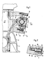
- a reciprocating piston internal combustion engine 1 comprises a cylinder crankcase 2, on the longitudinal side 3 of which a balancer shaft 4 extends, which serves for vibration damping (inertial forces, gas forces).
- the balance shaft 4 has balance weights 5, 6 and rotates at double the crankshaft speed in a bearing housing 7, which is formed by two housing halves 8, 9.
- the housing halves 8, 9 are held in position by means of screws 10, 11.
- the bearing housing 7 is also held by means of screws 12, 13 which are arranged at a distance from one another and are provided at 14 and 15 (FIG. 3). 7 mounting sections 16, 17 are attached to the cylinder crankcase 2 for receiving the bearing housing.
- the screw 12 (at 14) and the screws, not shown, at 15 are formed by conventional hexagon screws.
- the screw 13 is represented by a stud 24, the threaded pin 25 of which is screwed into a threaded bore 26.
- the threaded pin 25 is supported by means of a conical projection 27 on a corresponding chamfer 28 of the cylinder crankcase 2, whereby forces acting on the threaded pin 23 are supported.
- a screw nut 29 of the stud screw 22 has a conical projection 30 which interacts with a corresponding chamfer 31 of the bearing housing 7.
- the screw nut 29 is accessible via a recess 32 in the bearing housing 7.
Landscapes
- Engineering & Computer Science (AREA)
- Mechanical Engineering (AREA)
- General Engineering & Computer Science (AREA)
- Chemical & Material Sciences (AREA)
- Combustion & Propulsion (AREA)
- Cylinder Crankcases Of Internal Combustion Engines (AREA)
- Pistons, Piston Rings, And Cylinders (AREA)
Claims (1)
- Moteur à combustion interne à pistons alternatifs, de préférence de type à quatre cylindres, comportant au moins un arbre d'équilibrage amortissant les vibrations (4) placé de façon à pouvoir tourner dans un logement de paliers (7) fixé à un carter de vilebrequin (2) au moyen d'un assemblage parvis, caractérisé en ce que l'assemblage par vis comporte au moins une vis à goujon (24) pourvue d'un renflement conique (27) qui s'appuie sur un chanfrein (28) du carter de vilebrequin (2), et en ce que la vis à goujon est reliée à un écrou taraudé (29) comportant un renflement (30) également conique, ce renflement (30) de l'écrou coopérant avec un chanfrein (31) du logement de paliers (7).
Applications Claiming Priority (2)
| Application Number | Priority Date | Filing Date | Title |
|---|---|---|---|
| DE3138165 | 1981-09-25 | ||
| DE19813138165 DE3138165A1 (de) | 1981-09-25 | 1981-09-25 | "hubkolbenbrennkratfmaschine, vorzugsweise vierzylindriger bauart" |
Publications (3)
| Publication Number | Publication Date |
|---|---|
| EP0075659A2 EP0075659A2 (fr) | 1983-04-06 |
| EP0075659A3 EP0075659A3 (en) | 1983-08-03 |
| EP0075659B1 true EP0075659B1 (fr) | 1986-01-29 |
Family
ID=6142576
Family Applications (1)
| Application Number | Title | Priority Date | Filing Date |
|---|---|---|---|
| EP82105814A Expired EP0075659B1 (fr) | 1981-09-25 | 1982-06-30 | Moteur à combustion à quatre cylindres |
Country Status (4)
| Country | Link |
|---|---|
| US (1) | US4510898A (fr) |
| EP (1) | EP0075659B1 (fr) |
| JP (1) | JPS5868532A (fr) |
| DE (2) | DE3138165A1 (fr) |
Families Citing this family (16)
| Publication number | Priority date | Publication date | Assignee | Title |
|---|---|---|---|---|
| US4703724A (en) * | 1986-05-29 | 1987-11-03 | Chrysler Motors Corporation | Engine balancing device with a lubricant side discharge |
| US4677948A (en) * | 1986-05-29 | 1987-07-07 | Chrysler Motors Corporation | Lubricating system for an engine balancing device |
| US4703725A (en) * | 1986-05-29 | 1987-11-03 | Chrysler Motors Corporation | Mounting of an engine balancing device |
| DE3626528C1 (de) * | 1986-08-05 | 1988-02-25 | Bayerische Motoren Werke Ag | Einstellvorrichtung fuer ein lageverstellbares,mit einem Getriebeelement ausgeruestetes Bauteil einer Spannvorrichtung fuer Huellgetriebe |
| FR2619881B1 (fr) * | 1987-08-31 | 1990-01-19 | Peugeot | Arbre d'equilibrage pour moteur a pistons alternatifs |
| JPH01114953U (fr) * | 1988-01-28 | 1989-08-02 | ||
| DE3919503A1 (de) * | 1989-06-15 | 1990-12-20 | Daimler Benz Ag | Verfahren zum ausgerichteten befestigen eines gegengewichts an einer kurbelwelle und werkzeug zur durchfuehrung des verfahrens |
| DE4223780C2 (de) * | 1992-07-18 | 1996-04-11 | Bayerische Motoren Werke Ag | Schraubverbindung für einen Zylinderkopf einer Brennkraftmaschine |
| DE10241883B4 (de) * | 2002-09-10 | 2012-06-21 | Andreas Stihl Ag & Co. | Handgeführtes Arbeitsgerät mit einem Befestigungsstift für einen Abgasschalldämpfer |
| AT7764U1 (de) | 2003-12-02 | 2005-08-25 | Magna Drivetrain Ag & Co Kg | Kolbenmaschine mit integrierten ausgleichswellen |
| DE102009041708A1 (de) * | 2009-09-16 | 2011-03-24 | GM Global Technology Operations, Inc., Detroit | Schraubenpfeife für einen Zylinderkopf einer Brennkraftmaschine, Zylinderkopf, Brennkraftmaschine und Fahrzeug sowie Verfahren zur Herstellung einer Schraubenpfeife |
| US20140216390A1 (en) * | 2010-11-23 | 2014-08-07 | Jacob M. Wiebe | Stud fasteners for fastening a cylinder head to an engine block and kit containing said stud fasteners |
| EP3686410B1 (fr) * | 2019-01-23 | 2023-05-24 | Volvo Car Corporation | Ensemble de boîtier |
| DE102019002996A1 (de) * | 2019-04-25 | 2020-10-29 | Deutz Aktiengesellschaft | Kurbelgehäuse mit gestufter Stiftschraube |
| EP3741485B1 (fr) * | 2019-05-20 | 2024-07-03 | Andreas Stihl AG & Co. KG | Appareil de travail et goujons pour un appareil de travail |
| US20250027525A1 (en) * | 2023-07-21 | 2025-01-23 | Spirit Aerosystems, Inc. | Indexing bolt for joining composite form pieces together |
Family Cites Families (7)
| Publication number | Priority date | Publication date | Assignee | Title |
|---|---|---|---|---|
| CH220808A (fr) * | 1939-12-30 | 1942-04-30 | Bechler Andre | Dispositif de raccordement axial par vis de deux pièces cylindriques. |
| US3115356A (en) * | 1960-05-31 | 1963-12-24 | Ernest F Hohwart | Self positioning accurately remountable dowell |
| US3245142A (en) * | 1964-11-10 | 1966-04-12 | Durabla Mfg Company | Method of assembling low stress threaded connection |
| GB1231212A (fr) * | 1968-05-06 | 1971-05-12 | ||
| DE1780504A1 (de) * | 1968-09-23 | 1972-02-03 | Kronprinz Ag | Zentrierende Fahrzeugradbefestigung fuer einteiige Radscheiben von Fahrzeugraedern |
| JPS5175808A (en) * | 1974-12-26 | 1976-06-30 | Mitsubishi Motors Corp | Enjinno baransakudosochi |
| DE2935384A1 (de) * | 1979-09-01 | 1981-03-19 | Daimler-Benz Ag, 7000 Stuttgart | Brennkraftmaschine mit einem massenausgleich zweiter ordnung |
-
1981
- 1981-09-25 DE DE19813138165 patent/DE3138165A1/de not_active Withdrawn
-
1982
- 1982-06-30 DE DE8282105814T patent/DE3268790D1/de not_active Expired
- 1982-06-30 EP EP82105814A patent/EP0075659B1/fr not_active Expired
- 1982-09-24 JP JP57165184A patent/JPS5868532A/ja active Pending
- 1982-09-27 US US06/424,372 patent/US4510898A/en not_active Expired - Fee Related
Also Published As
| Publication number | Publication date |
|---|---|
| DE3138165A1 (de) | 1983-04-14 |
| US4510898A (en) | 1985-04-16 |
| EP0075659A2 (fr) | 1983-04-06 |
| EP0075659A3 (en) | 1983-08-03 |
| JPS5868532A (ja) | 1983-04-23 |
| DE3268790D1 (en) | 1986-03-13 |
Similar Documents
| Publication | Publication Date | Title |
|---|---|---|
| EP0075659B1 (fr) | Moteur à combustion à quatre cylindres | |
| DE4228334A1 (de) | Saugrohranlage für eine Mehrzylinder-Brennkraftmaschine | |
| DE102016117649B4 (de) | Verfahren zum Auswuchten einer Kurbelwelle | |
| DE4330565C1 (de) | Kurbelwellenlager | |
| EP0809041B1 (fr) | Dispositif d'équilibrage de torsion inertiel des moteurs à combustion interne | |
| DE602004000201T2 (de) | Verbindungsstange zwischen zwei mechanischen Teilen | |
| DE4228689A1 (de) | Motorblock | |
| DE3122533A1 (de) | Brennkraftmaschine | |
| EP0749861A2 (fr) | Disque d'entraînement entre un moteur alternatif à combustion interne et un convertisseur de couple | |
| DE4434994C2 (de) | Kolben für Brennkraftmaschinen | |
| DE4110347C2 (de) | Befestigungsanordnung für eine Ablenkplatte in einem Motor | |
| EP0228533B1 (fr) | Moteur à combustion interne avec au moins un arbre à came en tête | |
| DE2153258A1 (de) | Anordnung der Zuganker und Grundlager schrauben in Gehäusen von Hubkolbenma schinen | |
| EP1024276B1 (fr) | Moteur à pistons à combustion interne | |
| DE3119362C2 (de) | Vierzylinder-Brennkraftmaschine mit einem Massenausgleich zweiter Ordnung | |
| DE3933103A1 (de) | Pleuel, insbesondere leichtmetallpleuel | |
| CH383083A (de) | Kurbelwelle | |
| DE69502511T2 (de) | Zusammenbau einer Kipphebelwelle in einem Zylinderkopf einer Brennkraftmaschine | |
| DE2126059A1 (de) | Kurbelwelle mit Pleuellager fur Hub kolbenmaschinen | |
| DE3225975C1 (de) | Zusammengesetzte Kurbelwelle | |
| DE2802603A1 (de) | Geteilter pleuelkopf | |
| DE3626530C1 (de) | Anordnung eines Aggregates mittels der Verschraubung eines hochbelasteten Maschinenteils,insbesondere bei Brennkraftmaschinen | |
| DE2706021A1 (de) | Verfahren fuer die montierung einer nockenwelle | |
| DE4137534A1 (de) | Motorblock einer brennkraftmaschine | |
| EP0276372A1 (fr) | Arbre à cames dans un moteur à combustion interne |
Legal Events
| Date | Code | Title | Description |
|---|---|---|---|
| PUAI | Public reference made under article 153(3) epc to a published international application that has entered the european phase |
Free format text: ORIGINAL CODE: 0009012 |
|
| AK | Designated contracting states |
Designated state(s): DE FR GB IT NL SE |
|
| PUAL | Search report despatched |
Free format text: ORIGINAL CODE: 0009013 |
|
| AK | Designated contracting states |
Designated state(s): DE FR GB IT NL SE |
|
| 17P | Request for examination filed |
Effective date: 19830802 |
|
| ITF | It: translation for a ep patent filed | ||
| GRAA | (expected) grant |
Free format text: ORIGINAL CODE: 0009210 |
|
| AK | Designated contracting states |
Designated state(s): DE FR GB IT NL SE |
|
| REF | Corresponds to: |
Ref document number: 3268790 Country of ref document: DE Date of ref document: 19860313 |
|
| ET | Fr: translation filed | ||
| PLBE | No opposition filed within time limit |
Free format text: ORIGINAL CODE: 0009261 |
|
| STAA | Information on the status of an ep patent application or granted ep patent |
Free format text: STATUS: NO OPPOSITION FILED WITHIN TIME LIMIT |
|
| 26N | No opposition filed | ||
| PGFP | Annual fee paid to national office [announced via postgrant information from national office to epo] |
Ref country code: SE Payment date: 19900529 Year of fee payment: 9 |
|
| PGFP | Annual fee paid to national office [announced via postgrant information from national office to epo] |
Ref country code: DE Payment date: 19900613 Year of fee payment: 9 |
|
| PGFP | Annual fee paid to national office [announced via postgrant information from national office to epo] |
Ref country code: GB Payment date: 19900619 Year of fee payment: 9 |
|
| PGFP | Annual fee paid to national office [announced via postgrant information from national office to epo] |
Ref country code: FR Payment date: 19900627 Year of fee payment: 9 |
|
| ITTA | It: last paid annual fee | ||
| PGFP | Annual fee paid to national office [announced via postgrant information from national office to epo] |
Ref country code: NL Payment date: 19900630 Year of fee payment: 9 |
|
| PG25 | Lapsed in a contracting state [announced via postgrant information from national office to epo] |
Ref country code: GB Effective date: 19910630 |
|
| PG25 | Lapsed in a contracting state [announced via postgrant information from national office to epo] |
Ref country code: SE Effective date: 19910701 |
|
| PG25 | Lapsed in a contracting state [announced via postgrant information from national office to epo] |
Ref country code: NL Effective date: 19920101 |
|
| NLV4 | Nl: lapsed or anulled due to non-payment of the annual fee | ||
| GBPC | Gb: european patent ceased through non-payment of renewal fee | ||
| PG25 | Lapsed in a contracting state [announced via postgrant information from national office to epo] |
Ref country code: FR Effective date: 19920228 |
|
| PG25 | Lapsed in a contracting state [announced via postgrant information from national office to epo] |
Ref country code: DE Effective date: 19920401 |
|
| REG | Reference to a national code |
Ref country code: FR Ref legal event code: ST |
|
| EUG | Se: european patent has lapsed |
Ref document number: 82105814.6 Effective date: 19920210 |