EP0749862B1 - Dispositif d'entrainement de roulage pour engin de travaux publics - Google Patents
Dispositif d'entrainement de roulage pour engin de travaux publics Download PDFInfo
- Publication number
- EP0749862B1 EP0749862B1 EP95910761A EP95910761A EP0749862B1 EP 0749862 B1 EP0749862 B1 EP 0749862B1 EP 95910761 A EP95910761 A EP 95910761A EP 95910761 A EP95910761 A EP 95910761A EP 0749862 B1 EP0749862 B1 EP 0749862B1
- Authority
- EP
- European Patent Office
- Prior art keywords
- hydraulic
- hand side
- wheel
- drive apparatus
- working vehicle
- Prior art date
- Legal status (The legal status is an assumption and is not a legal conclusion. Google has not performed a legal analysis and makes no representation as to the accuracy of the status listed.)
- Expired - Lifetime
Links
Images




Classifications
-
- B—PERFORMING OPERATIONS; TRANSPORTING
- B60—VEHICLES IN GENERAL
- B60K—ARRANGEMENT OR MOUNTING OF PROPULSION UNITS OR OF TRANSMISSIONS IN VEHICLES; ARRANGEMENT OR MOUNTING OF PLURAL DIVERSE PRIME-MOVERS IN VEHICLES; AUXILIARY DRIVES FOR VEHICLES; INSTRUMENTATION OR DASHBOARDS FOR VEHICLES; ARRANGEMENTS IN CONNECTION WITH COOLING, AIR INTAKE, GAS EXHAUST OR FUEL SUPPLY OF PROPULSION UNITS IN VEHICLES
- B60K23/00—Arrangement or mounting of control devices for vehicle transmissions, or parts thereof, not otherwise provided for
- B60K23/08—Arrangement or mounting of control devices for vehicle transmissions, or parts thereof, not otherwise provided for for changing number of driven wheels, for switching from driving one axle to driving two or more axles
- B60K23/0808—Arrangement or mounting of control devices for vehicle transmissions, or parts thereof, not otherwise provided for for changing number of driven wheels, for switching from driving one axle to driving two or more axles for varying torque distribution between driven axles, e.g. by transfer clutch
-
- B—PERFORMING OPERATIONS; TRANSPORTING
- B60—VEHICLES IN GENERAL
- B60K—ARRANGEMENT OR MOUNTING OF PROPULSION UNITS OR OF TRANSMISSIONS IN VEHICLES; ARRANGEMENT OR MOUNTING OF PLURAL DIVERSE PRIME-MOVERS IN VEHICLES; AUXILIARY DRIVES FOR VEHICLES; INSTRUMENTATION OR DASHBOARDS FOR VEHICLES; ARRANGEMENTS IN CONNECTION WITH COOLING, AIR INTAKE, GAS EXHAUST OR FUEL SUPPLY OF PROPULSION UNITS IN VEHICLES
- B60K17/00—Arrangement or mounting of transmissions in vehicles
- B60K17/04—Arrangement or mounting of transmissions in vehicles characterised by arrangement, location or kind of gearing
- B60K17/043—Transmission unit disposed in on near the vehicle wheel, or between the differential gear unit and the wheel
-
- B—PERFORMING OPERATIONS; TRANSPORTING
- B60—VEHICLES IN GENERAL
- B60K—ARRANGEMENT OR MOUNTING OF PROPULSION UNITS OR OF TRANSMISSIONS IN VEHICLES; ARRANGEMENT OR MOUNTING OF PLURAL DIVERSE PRIME-MOVERS IN VEHICLES; AUXILIARY DRIVES FOR VEHICLES; INSTRUMENTATION OR DASHBOARDS FOR VEHICLES; ARRANGEMENTS IN CONNECTION WITH COOLING, AIR INTAKE, GAS EXHAUST OR FUEL SUPPLY OF PROPULSION UNITS IN VEHICLES
- B60K17/00—Arrangement or mounting of transmissions in vehicles
- B60K17/04—Arrangement or mounting of transmissions in vehicles characterised by arrangement, location or kind of gearing
- B60K17/043—Transmission unit disposed in on near the vehicle wheel, or between the differential gear unit and the wheel
- B60K17/046—Transmission unit disposed in on near the vehicle wheel, or between the differential gear unit and the wheel with planetary gearing having orbital motion
-
- B—PERFORMING OPERATIONS; TRANSPORTING
- B60—VEHICLES IN GENERAL
- B60K—ARRANGEMENT OR MOUNTING OF PROPULSION UNITS OR OF TRANSMISSIONS IN VEHICLES; ARRANGEMENT OR MOUNTING OF PLURAL DIVERSE PRIME-MOVERS IN VEHICLES; AUXILIARY DRIVES FOR VEHICLES; INSTRUMENTATION OR DASHBOARDS FOR VEHICLES; ARRANGEMENTS IN CONNECTION WITH COOLING, AIR INTAKE, GAS EXHAUST OR FUEL SUPPLY OF PROPULSION UNITS IN VEHICLES
- B60K17/00—Arrangement or mounting of transmissions in vehicles
- B60K17/34—Arrangement or mounting of transmissions in vehicles for driving both front and rear wheels, e.g. four wheel drive vehicles
- B60K17/356—Arrangement or mounting of transmissions in vehicles for driving both front and rear wheels, e.g. four wheel drive vehicles having fluid or electric motor, for driving one or more wheels
-
- F—MECHANICAL ENGINEERING; LIGHTING; HEATING; WEAPONS; BLASTING
- F16—ENGINEERING ELEMENTS AND UNITS; GENERAL MEASURES FOR PRODUCING AND MAINTAINING EFFECTIVE FUNCTIONING OF MACHINES OR INSTALLATIONS; THERMAL INSULATION IN GENERAL
- F16H—GEARING
- F16H37/00—Combinations of mechanical gearings, not provided for in groups F16H1/00 - F16H35/00
- F16H37/02—Combinations of mechanical gearings, not provided for in groups F16H1/00 - F16H35/00 comprising essentially only toothed or friction gearings
- F16H37/06—Combinations of mechanical gearings, not provided for in groups F16H1/00 - F16H35/00 comprising essentially only toothed or friction gearings with a plurality of driving or driven shafts; with arrangements for dividing torque between two or more intermediate shafts
- F16H37/08—Combinations of mechanical gearings, not provided for in groups F16H1/00 - F16H35/00 comprising essentially only toothed or friction gearings with a plurality of driving or driven shafts; with arrangements for dividing torque between two or more intermediate shafts with differential gearing
- F16H37/0833—Combinations of mechanical gearings, not provided for in groups F16H1/00 - F16H35/00 comprising essentially only toothed or friction gearings with a plurality of driving or driven shafts; with arrangements for dividing torque between two or more intermediate shafts with differential gearing with arrangements for dividing torque between two or more intermediate shafts, i.e. with two or more internal power paths
- F16H37/084—Combinations of mechanical gearings, not provided for in groups F16H1/00 - F16H35/00 comprising essentially only toothed or friction gearings with a plurality of driving or driven shafts; with arrangements for dividing torque between two or more intermediate shafts with differential gearing with arrangements for dividing torque between two or more intermediate shafts, i.e. with two or more internal power paths at least one power path being a continuously variable transmission, i.e. CVT
- F16H2037/088—Power-split transmissions with summing differentials, with the input of the CVT connected or connectable to the input shaft
-
- F—MECHANICAL ENGINEERING; LIGHTING; HEATING; WEAPONS; BLASTING
- F16—ENGINEERING ELEMENTS AND UNITS; GENERAL MEASURES FOR PRODUCING AND MAINTAINING EFFECTIVE FUNCTIONING OF MACHINES OR INSTALLATIONS; THERMAL INSULATION IN GENERAL
- F16H—GEARING
- F16H47/00—Combinations of mechanical gearing with fluid clutches or fluid gearing
- F16H47/02—Combinations of mechanical gearing with fluid clutches or fluid gearing the fluid gearing being of the volumetric type
- F16H47/04—Combinations of mechanical gearing with fluid clutches or fluid gearing the fluid gearing being of the volumetric type the mechanical gearing being of the type with members having orbital motion
Definitions
- the present invention relates to a traveling drive apparatus in a working vehicle with the features of the precharacterizing part of claim 1.
- a traveling drive apparatus is known from W093/09002.
- Such a working vehicle comprises a working machine such as an excavator or a crane mounted on a traveling body thereof.
- the traveling drive apparatus of such a working vehicle is made capable of traveling in four wheel drive mode with a pair of front wheels and a pair of rear wheels.
- WO93/09002 discloses a power transmission system with radial piston-type hub motors each turning one wheel, a gear and a clutch for connecting a hydraulic motor to a differential, two valves, a hydraulic pump driven by an engine, and a toothed coupling for connecting a hydraulic pump or engine directly to the differential.
- the hydraulic motor may be coupled with wheels for driving or a gear box and the hydraulic motor can be disengaged and the engine may be coupled with toothed coupling right over the differential to the driving wheel instead.
- WO93/09002 it is an object of the invention to provide a traveling drive apparatus in a working vehicle which is capable of effecting a simplification of the hydraulic circuit arrangement in its construction and is also capable of enhancing the ability of said vehicle to travel on soft and weak ground sites as well as on unleveled or unprepared ground wherein said hydraulic motors are provided for independently driving the vehicle wheels with reducing the costs for in the power transmission device.
- the engine and the hydraulic motors mentioned above can selectively be combined in their driving operations. Accordingly, it is possible to shift a speed ratio and thus lessen the speed ratios of the transmission provided around the power transmission device for the said engine, thereby largely reducing the cost involved in the said transmission.
- the construction in which the left hand side and right hand side wheels on the front side are driven by hydraulic motors which are provided independently of each other will enable the rates of rotation and the torques of the left hand side and right hand side wheels on the front side to be respectively varied, thus improving the ability for the traveling body to travel on a soft and weak ground as well as on an unleveled or unprepared ground.
- said suspension unit for the said left hand side wheel and the said right hand side wheel of the said other of the said front side and the said rear side is provided with a clutch for connecting and disconnecting them with the said second hydraulic motor and third hydraulic motors, respectively.
- the said hydraulic motors for driving the right hand side and left hand side wheels on the front side independently of each other are disposed in the interior of the said steering knuckle arm it effectively protects those hydraulic motors from an earth, sand and rock discharge from the road on which the vehicle is traveling.
- the said second and third hydraulic motors should be constructed integrally with a spindle which is securely fastened to a said steering knuckle arm.
- the said spindle securely fastened to the said steering knuckle arm should have a rim member supported thereon which is securely fastened with a said wheel, that an input shaft supported on the said spindle and the said rim member should be coupled to each other via a reduction gear of planetary gear type provided in the said rim member, and that the said input shaft should be coupled to the respective output shafts of the said second and third hydraulic motors.
- the said clutch should be of a disk plate configuration or alternatively of a coupling configuration in which a coupling is engageable with and disengageable from the said output shafts and the said input shaft.
- a clutch of a disk plate configuration should be interposed between an intermediary rotary member that can be constituted by a ring gear or a carrier on the one hand and a wheel hub for said reduction gear on the other hand.
- Fig. 1 is a side view diagrammatically illustrating a working vehicle that incorporates a certain embodiment of the present invention.
- Fig. 2 is a top plan view diagrammatically illustrating the above mentioned working vehicle and the above mentioned embodiment of the present invention.
- Fig. 3 is a diagrammatic view illustrating a transmission and a hydraulic circuit in the above mentioned embodiment of the present invention.
- Fig. 4 is a diagrammatic view illustrating a specific example of the hydraulic circuit shown in Fig. 3.
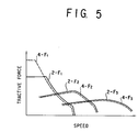
- Fig. 5 is a graph diagrammatically illustrating the relationship between the speed and the tractive force in each speed ratio in the above mentioned embodiment.
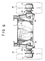
- Fig. 6 is front view, partly cut away, illustrating diagrammatically a first alternative example of a suspension unit for the front wheels.
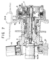
- Fig. 7 is an enlarged cross sectional view, partly cut away, diagrammatically illustrating the first alternative example of the above mentioned suspension unit for the front wheels.
- Fig. 8 is an enlarged cross sectional view, partly cut away, diagrammatically illustrating a second alternative example of the suspension unit for the front wheels.
- Fig. 9 is an enlarged cross sectional view, partly cut away, diagrammatically illustrating a third alternative example of the suspension unit for the front wheels.
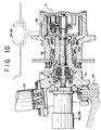
- Fig. 10 is an enlarged cross sectional view, partly cut away, diagrammatically illustrating a fourth alternative example of the suspension unit for the front wheels.
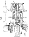
- Fig. 11 is an enlarged cross sectional view, partly cut away, diagrammatically illustrating a fifth alternative example of the suspension unit for the front wheels.
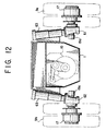
- Fig. 12 is an enlarged cross sectional view, partly cut away, diagrammatically illustrating a sixth alternative example of the suspension unit for the front wheels.
- Figs. 1 and 2 show an example of the working vehicle which incorporates an certain example of the traveling drive apparatus according to the present invention.
- a chassis 1 i. e. a frame for a traveling body
- the said turning body 2 has a working machine 6 mounted thereof which includes an excavating unit 4, a cabin 5 and so forth.
- a central swivel joint 7 that is located between the said chassis 1 and the said turning body 2.
- the said chassis 1 is provided with a left hand side and a right hand side wheel 8a and 8b on the rear side, a left hand side and a right hand side wheels 9a and 9b on the front side, an engine 10, a transmission 11, a hydraulic pump 12 and a hydraulic motor 13 (first hydraulic motor) for the rear wheels 8a and 8b. And, the respective wheel shafts of the left hand side and right hand side wheels 8a and 8b on the rear side are coupled to the output shaft of the said transmission 11 via a differential unit 14 and a propeller shaft 15.
- the left hand side and right hand side wheels 9a and 9b on the front side are respectively coupled via a pair of reduction gears 17 and a pair of clutches 18 equipped in their respective wheel hubs to the respective shafts of a pair of hydraulic motors 19a and 19b (second and third hydraulic motor) which are provided independently of each other for the front wheels.
- a pair of hydraulic motors 19a and 19b second and third hydraulic motor
- Each of the said hydraulic motors 19a and 19b for the front wheels is equipped in a portion of a suspension unit which suspends the front wheels and which will be described later in detail.
- the left hand side and right hand side rear wheel shaft and the left hand side and right hand side front wheel shaft are provided with service brakes, respectively.
- Fig. 3 shows the said transmission 11 and a hydraulic circuit 28 in the above mentioned embodiment for driving the rear wheels 8a and 8b and the front wheels 9a and 9b.
- the said transmission 11 is provided with a first input shaft 21 and a second input shaft 22.
- the first input shaft 21 has one end that is connected to the output shaft of the said engine and the other end that is connected to the input shaft of the said hydraulic motor 12.
- the said first input shaft 21 is connected to a speed ratio shifting gear section 26 having a gear train 23, a gear train 24 and a gear train 25 for the second speed ratio, the third speed ratio and the fourth speed ratio, respectively, the said speed ratio shifting gear section 26 having an output side that is connected to the said propeller shaft 15 via a pair of spur gears A and B , respectively.
- the spur gear A is supported via a bearing on a carrier 27a of a planetary gear train 27.
- the said second shaft 22 has one end that is connected to the output shaft of the above mentioned hydraulic motor 13 for the rear wheels and the other end that is connected to the said propeller shaft 15 via a planetary gear train 27 and a spur gear C .
- the hydraulic motor 13 for the rear wheels and the hydraulic motors 19a and 19b for the front wheels mentioned above are connected to the said hydraulic pump 12 via respective control valves 29a and 29b in the said hydraulic circuit 28 of an open circuit configuration.
- Fig. 4 shows a specific example of the above mentioned hydraulic circuit 28.
- This hydraulic circuit 28 having an open circuit construction is connected to a plurality of cylinders 30a and 30b of the said excavation unit 4 in the said working machine 6 and to a turning motor 31 for driving the said upper turning body 2 via control valves 32a, 32b and 32c, respectively, and in parallel to the hydraulic motor 13 for the rear wheels and the hydraulic motors 19a and 19c for the front wheels mentioned above.
- the left hand side and right hand side front wheels 9a and 9b are, as shown in Fig. 2, supported by a suspension unit of equalizer bar type. More specifically, those front wheels 9a and 9b are supported at the both ends of an equalizer bar 33 via a pair of knuckle arms 34 so as to be steering operable and are adapted to be steering operated via a steering rod 35 and a steering cylinder 36.
- the both ends of the said equalizer bar 33 is supported with a pair of suspension cylinders 37 having a locking mechanism.
- the above mentioned hydraulic motors 19a and 19b for driving the left hand side and right hand side front wheels 9a and 9b are supported by the above mentioned pair of knuckle arms 34.
- the front wheels 9a and 9b will be driven by the said hydraulic motors 19 and 19a for the front wheels which motors are rotated by the discharge fluid from the above mentioned hydraulic pump 12.
- the power for transmission to the said speed ratio shifting gear section 26 within the above mentioned transmission 11 will be transmitted to the said propeller shaft 15 via the said spur gears A and B by selectively turning ON the respective clutches 23a, 24a and 25a of the above mentioned speed ratio gear trains 23, 24 and 25.
- each speed ratio that is configured by selectively using a respective one of the clutches 23a, 24a and 25b of each of the speed ratio gear trains 23, 24 and 25 in the said speed ratio shifting gear section 26 and each of the said hydraulic motors 13, 19a and 19b, each for the case of backing with both the rear wheels 8a and 8b and the front wheels 9a and 9b, for the case of two wheel drive with the rear wheels 8a and 8b and for the case of four wheel drive with both the rear wheels 8a and 8b and the front-wheels 9a and 9b.
- Table 1 listed below shows the ON/OFF states of the power from the engine 10, the power from the hydraulic motor 13 for the rear wheels and the power from the hydraulic motors 19a and 19b for the front wheels in each speed ratio for the case of backing, for the case of two wheel drive and for the case of four wheel drive.
- the hydraulic motor 13 for the rear wheels and the hydraulic motors for the front wheels 19a and 19b are reversely rotated controlledly so that the vehicle may be backed in a four wheel drive mode with hydraulic motors 13, 19a and 19b.
- a transmission of the power from the hydraulic motor 13 for the rear wheels and the hydraulic motors 19a and 19b for the front wheels will be disabled or held OFF while the power of the engine 10 will be transmitted by the spur gears A and B by holding ON the clutch 23a in the speed ratio gear train 23 for the two speed ratios in the speed ratio sifting gear section 26 to drive the rear wheels 8a and 8b.
- the planetary gear train 27 of the second input shaft 22 will then be held OFF.
- a transmission of the power from each of the hydraulic motors 13, 19a and 19b will be disabled or held OFF and each of the respective clutches 24a and 25b of the three speed stepped gear train 24 and the four speed ratio gear train 25 will be held ON to allow the power of the engine 10 to be transmitted by the spur gears A and B , thereby driving the rear wheels 8a and 8b.
- the clutch 27a of the planetary gear train 27 will be held OFF.
- the hydraulic motor 13 for the rear wheels and the hydraulic motors 19a and 19b for the front wheels will each be positively rotated controlledly to drive the wheels 8a and 8b and 9a and 9b with those hydraulic motors 13, 19a and 19b. This is similar to the case in which the vehicle is backed and will allow it to travel at an increased force of traction. The power from the engine 10 will then be held OFF.
- the clutch 23a of the second speed ratio gear train 23 in the speed ratio shifting gear section 26 will be held ON to transmit the power from the engine 10, thereby driving the rear wheels 8a and 8b. Also, a transmission of the power from the hydraulic motors 19a and 19b for the front wheels will be enabled or held ON to drive the front wheels 9a and 9b. A transmission of the power from the hydraulic motor 13 for the rear wheels will then be disabled or held OFF.
- a transmission of the power from each of the hydraulic motors 19a and 19b will be enabled or held ON.
- Each of the respective clutches 24a and 25a of the third speed ratio gear train 24 and the fourth speed ratio gear train 25 in the speed ratio shifting gear section 26 will be enabled or held ON.
- the rear wheels 8a and 8b for each of the third speed ratio and fourth speed ratio control modes will thereby be driven at a respective change gear ratio in the speed ratio shifting gear section 26 by the power from the engine 10 while the front wheels 9a and 9b will be driven by the hydraulic motors 19a and 19b.
- a transmission of the power from the hydraulic motor 13 for the rear wheels will then be disabled or held OFF.
- the front wheels 9a and 9b can be selectively turned ON and OFF in their driving by turning their respective clutches 18 which are equipped around their shafts, respectively.
- each of the hydraulic motors 13, 19a and 19b being of a variable capacity type, they can be controlled so that each of them may have a speed of rotation selected in accordance with each speed ratio. It should be noted, however, that each of these hydraulic motors may be of a fixed capacity type.
- the said working machines on the turning body 2 can be operated by controlling the said cylinders 30a and 30b for the working machines and the said turning motor 31 on the upper turning body via the said respective control valves 32a, 32b and 32c for the working machines.
- a pressurized fluid to each of the said actuators will then be supplied from the above mentioned hydraulic pump 12 for traveling.
- the said hydraulic pump 12 are designed to serve to achieve the both purposes of traveling and working. Accordingly, each of the above mentioned working machine components can be operated while they are traveling with the vehicle.
- a pair of suspension links 40 are coupled to the both sides of the said chassis 1, respectively, so as to be turnable upwards and downwards.
- Each of the said suspension links 40 has at its forward end a steering knuckle arm coupled thereto and also has the lower end of a suspension cylinder 42 coupled to the steering knuckle arm, whose upper end is coupled to the said chassis 1. Also, these steering knuckle arms 41 are connected to the front wheels 9a and 9b, respectively.
- a spindle 43 has its one end that is securely fastened to the said steering knuckle arm 41 and its other end that is securely fastened to a wheel hub 44.
- the above mentioned spindle 43 has its axial portion at which an input shaft 45 is supported so as to be freely rotatable.
- the input shaft 45 has its one end that is connected to each of the respective output shafts 47 of the said hydraulic motors 19a and 19b for the front wheels which motors are coupled to the above mentioned steering knuckle arm 41 via a coupling 46.
- a rim member 48 for a said front wheel 9a, 9b is supported on the above mentioned wheel hub 44 so as to be freely rotatable.
- the said rim member 48 and the forward end of the above mentioned spindle 43 are coupled together via a reduction gear 17 of planetary gear construction.
- a clutch 18 for coupling and decoupling the said reduction gear 17 is provided in the inner periphery of the said wheel hub 44.
- the said clutch 18 is configured between the said inner periphery of the wheel hub 44 and the outer periphery of a ring gear member 49 of the said reduction gear 17 so that the said ring gear member 49 may selectively be fixed to the wheel hub 44 or may alternatively be freely rotatable.
- Fig. 8 shows the construction of a second alternative example of the said suspension unit for the front wheels 9a and 9b.
- the said clutch 18 is configured between the inner periphery of the said wheel hub 44 and a carrier 50 of the said reduction gear 17 so that the said carrier 50 may selectively be fixed to the wheel hub 44 or may alternatively be freely rotatable.
- Fig. 9 shows a third alternative example of the said suspension unit for the front wheels 9a and 9b, in which the supporting structure for the said hydraulic motors 19a and 19b for the front wheels are different from one in the examples mentioned above.
- a spindle 43a has a housing portion of the hydraulic motors 19a and 19b for the front wheels constructed integrally therewith, the respective output shafts of which motors are made integral with an input shaft 45a that is supported by the above mentioned spindle 43a.
- Fig. 10 shows a fourth alternative example of the said suspension unit for the front wheels 9a and 9b, in which the mounting site of the above mentioned clutch 18 is different.
- the said ring gear member 49 of the reduction gear 17 is securely fastened to the said wheel hub 44 whereas an input shaft 45b and the said rim member 48 are coupled together via the said reduction gear 17.
- the said clutch 18 is mounted between the said input shaft 45b and the respective output shafts 47 of the said hydraulic motors 19a and 19b.
- An operative piston 51 is provided at the side of the said steering knuckle arm 41 and a coupling 52 operative to be pushed by the said piston 51 is slidably engageable with a said output shaft 47 in its axial direction. And, a plurality of disk plates are provided between the inner periphery of a cylindrical member 53 securely fastened to the said coupling 52 and the outer periphery of the said input shaft 45 so as to be brought into an alternate contact therewith.
- a back plate 54 arranged to oppose to the above mentioned coupling 52 is supported by the said spindle 43a so as to be freely rotatable.
- this clutch 18 In a construction of the said clutch as shown in Fig. 10, it is possible for this clutch 18 to be compactly interposed between the said respective output shafts 47 of the hydraulic motors 19a and 19b for the front wheels and the said input shaft 45b for the front wheels 9a and 9b.
- Fig. 11 shows a fifth alternative example of the said suspension unit for the front wheels 9a and 9b, in which the construction of the said clutch 18 is further modified.
- the respective output shafts 47 of the hydraulic motors for the front wheels 19a and 19b and respective input shafts 45c for the front wheels 9a and 9b are adapted to be disengaged from one another by a sliding movement of a coupling 55.
- This coupling 55 is designed to be slidden by a piston 56 that is disposed in the said steering knuckle arm 41 and that is adapted to be returned by a spring 57 and also to be slidden in its engagement direction by a hydraulic force.
- Fig. 11 it should be noted that the position in which they are disengaged by the coupling 55 and the position in which they are engaged by the coupling 55 are shown above and below the center line of a said input shaft 45c and a said output shaft 47.
- each construction as mentioned above of the said suspension unit for the wheels 9a and 9b needs not necessarily to be of McPherson type and may similarly be served by a suspension unit 60 of equalizer bar type as shown in Fig. 2 or alternatively a suspension unit 61 of sliding pillar type as shown in Fig. 12.
- a pair of steering knuckle arms 62 are each supported at the forward end of a suspension cylinder 63 so as to be freely rotatable and have each in its interior a said hydraulic motor 19a, 19b that is disposed for a said front wheel.
Landscapes
- Engineering & Computer Science (AREA)
- Chemical & Material Sciences (AREA)
- Combustion & Propulsion (AREA)
- Transportation (AREA)
- Mechanical Engineering (AREA)
- Arrangement And Driving Of Transmission Devices (AREA)
- Arrangement Or Mounting Of Propulsion Units For Vehicles (AREA)
- Motor Power Transmission Devices (AREA)
Claims (10)
- Dispositif d'entraínement de roulage dans un engin de travaux publics comprenant un corps roulant (1) équipé de roues avant (9a, 9b) et de roues arrière (8a, 8b) qui sont adaptées pour être chacune commandée à entraínement,caractérisé en ce que ledit ensemble de suspension (61 ; 41, 48) pour ladite roue latérale gauche (9a, 8a) et ladite roue latérale droite (9b, 8b) de ladite autre de ladite partie avant et de ladite partie arrière est muni d'un embrayage (18) pour les accoupler ou les désaccoupler avec lesdits deuxième moteur hydraulique (19a) et troisième moteur hydraulique (19b) respectivement, et,ledit corps roulant (1) comporte, montés sur le corps roulant, un moteur (10), une boíte de vitesses (11) et une pompe hydraulique (12) qui sont couplées audit moteur (10) et un premier moteur hydraulique (13) qui est adapté pour être entraíné par ladite pompe hydraulique (12), tandis qu'une roue latérale gauche (9a, 8a) et une roue latérale droite (9b, 8b) sur l'une de la partie avant et de la partie arrière dudit corps roulant, sont adaptées pour être sélectivement couplées à l'un ou à l'autre d'un côté de sortie du moteur (10) et d'un côté de sortie dudit premier moteur hydraulique (13),et une roue latérale gauche (9a, 8a) et une roue latérale droite (9b, 8b) de l'autre de ladite partie avant et de ladite partie arrière, sont montées sur un ensemble de suspension (61 ; 41, 48) disposant d'un deuxième moteur hydraulique (19a) et d'un troisième moteur hydraulique (19b) indépendants l'un de l'autre et adaptés à être entraínés par ladite pompe hydraulique (12) et couplés respectivement à ladite roue latérale gauche et ladite roue latérale droite de ladite autre de ladite partie avant et de ladite partie arrière dudit corps roulant,
ladite machine de travaux publics (6) est montée sur ledit corps roulant (1) et ladite pompe hydraulique (12) présente un côté d'admission qui est relié à un côté de réservoir et présente un circuit de côté de refoulement qui est relié à chacun desdits moteurs hydrauliques (13, 19a, 19b) ainsi qu'à une pluralité d'actionneurs (30a, 30b, 31) pour ladite machine de travaux publics (6) disposés en parallèle, par l'intermédiaire de moyens d'actionnement de clapets (29a, 29b ; 32a, 32b, 32c). - Dispositif d'entraínement de roulage dans un engin de travaux publics suivant la revendication 1, caractérisé en ce que ledit ensemble de suspension (61 ; 41, 48) pour ladite roue latérale gauche (9a) et ladite roue latérale droite (9b) sur ladite partie avant, présente respectivement ledit deuxième moteur hydraulique (19a) et ledit troisième moteur hydraulique (19b) de façon indépendante l'un de l'autre, et chacun desdits deuxième et troisième moteurs hydrauliques est disposé à l'intérieur d'un bras d'articulation de direction (41) d'un dit bras de suspension.
- Dispositif d'entraínement de roulage dans un engin de travaux publics suivant la revendication 2, caractérisé en ce que lesdits deuxième et troisième moteurs hydrauliques (19a, b) sont formés solidairement avec un arbre (43) qui est fixé à un dit bras d'articulation de direction (41).
- Dispositif d'entraínement de roulage dans un engin de travaux publics suivant la revendication 2, caractérisé en ce qu'un arbre (43) solidaire dudit bras d'articulation de direction (41) supporte un élément de jante (48) qui est solidaire d'une desdites roues (9a, 9b) ; un arbre d'entrée (45) supporté par ledit arbre (43), et ledit élément de jante (48) sont couplés l'un à l'autre par l'intermédiaire d'un engrenage réducteur (17) de type engrenage planétaire disposé dans ledit élément de jante ; et ledit arbre d'entrée (45) est couplé aux arbres de sortie (47) respectifs desdits deuxième et troisième moteurs hydrauliques (19a, 19b).
- Dispositif d'entraínement de roulage dans un engin de travaux publics suivant la revendication 2, caractérisé en ce que des arbres de sortie respectifs (47) desdits deuxième et troisième moteurs hydrauliques (19a, 19b) et un arbre d'entrée (45) supporté par un arbre (43) solidaire dudit bras d'articulation de direction (41) sont couplés ensemble par l'intermédiaire d'un embrayage (18).
- Dispositif d'entraínement de roulage dans un engin de travaux publics suivant la revendication 5, caractérisé en ce que ledit embrayage (18) est de configuration à disque.
- Dispositif d'entraínement de roulage dans un engin de travaux publics suivant la revendication 5, caractérisé en ce que ledit embrayage (18) est de configuration à pièce d'accouplement dans laquelle une pièce d'accouplement est susceptible d'engagement et de désengagement par rapport auxdits arbres de sortie (47) et audit arbre d'entrée (45,45a-c).
- Dispositif d'entraínement de roulage dans un engin de travaux publics suivant la revendication 4, caractérisé en ce qu'un embrayage (18) de configuration à disque est inséré entre un organe rotatif intermédiaire (49, 50) et un moyeu de roue (44) pour ledit engrenage réducteur (17).
- Dispositif d'entraínement de roulage dans un engin de travaux publics suivant la revendication 8, caractérisé en ce que ledit organe rotatif intermédiaire (49, 50) est constitué par une couronne dentée (49).
- Dispositif d'entraínement de roulage dans un engin de travaux publics suivant la revendication 8, caractérisé en ce que ledit organe intermédiaire (49, 50) est constitué par un porte-satellites (50).
Applications Claiming Priority (4)
| Application Number | Priority Date | Filing Date | Title |
|---|---|---|---|
| JP3568794 | 1994-03-07 | ||
| JP6035687A JPH07242130A (ja) | 1994-03-07 | 1994-03-07 | 作業用車両の走行駆動装置 |
| JP35687/94 | 1994-03-07 | ||
| PCT/JP1995/000371 WO1995024325A1 (fr) | 1994-03-07 | 1995-03-07 | Dispositif d'entrainement de roulage pour engin de travaux publics |
Publications (3)
| Publication Number | Publication Date |
|---|---|
| EP0749862A1 EP0749862A1 (fr) | 1996-12-27 |
| EP0749862A4 EP0749862A4 (fr) | 1999-05-06 |
| EP0749862B1 true EP0749862B1 (fr) | 2000-08-23 |
Family
ID=12448816
Family Applications (1)
| Application Number | Title | Priority Date | Filing Date |
|---|---|---|---|
| EP95910761A Expired - Lifetime EP0749862B1 (fr) | 1994-03-07 | 1995-03-07 | Dispositif d'entrainement de roulage pour engin de travaux publics |
Country Status (6)
| Country | Link |
|---|---|
| US (1) | US5957235A (fr) |
| EP (1) | EP0749862B1 (fr) |
| JP (1) | JPH07242130A (fr) |
| KR (1) | KR100230674B1 (fr) |
| DE (1) | DE69518507T2 (fr) |
| WO (1) | WO1995024325A1 (fr) |
Families Citing this family (20)
| Publication number | Priority date | Publication date | Assignee | Title |
|---|---|---|---|---|
| US5906249A (en) * | 1995-12-22 | 1999-05-25 | Orion-yhtyma Oy | Drive system of a drive wheel |
| US6193086B1 (en) * | 1998-03-13 | 2001-02-27 | Marine Travelift, Inc. | Gantry crane with improved manually variable controls for movable components |
| US6098738A (en) * | 1998-07-08 | 2000-08-08 | White; Harvey | Hydraulic drive system for a vehicle |
| US6308441B1 (en) * | 1998-12-15 | 2001-10-30 | The Gradall Company | Excavator |
| DE19927702A1 (de) * | 1999-05-11 | 2000-11-16 | Martin Brenninger | Antrieb einer Achse für mehrachsige Fahrzeuge |
| DE19921856A1 (de) * | 1999-05-11 | 2000-11-16 | Martin Brenninger | Hydrostatisch-mechanischer Allradantrieb für mehrachsige Fahrzeuge |
| ATE324537T1 (de) * | 1999-06-14 | 2006-05-15 | Textron Inc | Zweiwege einzelpumpen, hydrostatischer antrieb für mäher |
| CA2282821C (fr) * | 1999-09-17 | 2007-11-27 | Champion Road Machinery Limited | Traction integrale pour niveleuse mecanique |
| US6860358B1 (en) | 2002-10-04 | 2005-03-01 | Hydro-Gear Limited Partnership | Utility vehicle having hydrostatic drive |
| ATE391043T1 (de) | 2003-12-11 | 2008-04-15 | Kanzaki Kokyukoki Mfg Co Ltd | Hydraulisches achsgetriebe und fahrzeug mit solchem achsgetriebe |
| US7111704B2 (en) * | 2004-01-30 | 2006-09-26 | Johnson Welded Products, Inc. | Hydrostatic drive apparatus for a road vehicle |
| JP2007039031A (ja) * | 2006-09-28 | 2007-02-15 | Kanzaki Kokyukoki Mfg Co Ltd | 作業車の走行駆動装置 |
| DE102009001603A1 (de) * | 2009-03-17 | 2010-09-23 | Zf Friedrichshafen Ag | Vorrichtung für einen Fahrzeugantriebsstrang |
| DE102010010472A1 (de) * | 2010-03-06 | 2011-09-08 | Daimler Ag | Kraftfahrzeug mit einem hydraulischen Zusatzantrieb |
| DE102011108893C5 (de) | 2011-07-29 | 2022-05-12 | Liebherr-Werk Ehingen Gmbh | Antriebsvorrichtung für einen Kran |
| CN106029472B (zh) * | 2014-02-27 | 2018-09-14 | 株式会社小松制作所 | 自卸车 |
| JP6401241B2 (ja) * | 2014-03-06 | 2018-10-10 | 住友建機株式会社 | ショベル |
| EP3609751A1 (fr) | 2017-04-11 | 2020-02-19 | Dana Italia S.r.L. | Circuit hydraulique pour système de freinage de stationnement adaptatif et son procédé de fonctionnement |
| KR102251962B1 (ko) * | 2017-06-20 | 2021-05-14 | 현대건설기계 주식회사 | 지게차용 유압시스템 |
| JP7804475B2 (ja) * | 2022-02-02 | 2026-01-22 | 株式会社小松製作所 | 履帯式作業機械 |
Family Cites Families (28)
| Publication number | Priority date | Publication date | Assignee | Title |
|---|---|---|---|---|
| US3690398A (en) * | 1970-10-05 | 1972-09-12 | Gen Motors Corp | Hydrostatic drive |
| US3844368A (en) * | 1972-01-24 | 1974-10-29 | V Melli | Hydraulic drive system |
| US3921746A (en) * | 1972-12-28 | 1975-11-25 | Alexander J Lewus | Auxiliary power system for automotive vehicle |
| US3980152A (en) * | 1973-03-14 | 1976-09-14 | Manor Robert T | Air powered vehicle |
| US4063608A (en) * | 1974-11-25 | 1977-12-20 | Sullivan Patrick D | Hydrostatic drive vehicle |
| US3954026A (en) * | 1974-12-06 | 1976-05-04 | Clark Equipment Company | Wheel drive mechanism |
| US4023641A (en) * | 1975-09-25 | 1977-05-17 | Ganoung David P | Powertrain and method for achieving low exhaust emission and high fuel economy operation of a combustion engine |
| US4020917A (en) * | 1975-11-07 | 1977-05-03 | Lutterschmidt Sigmund P | Positive hydraulic direct drive for vehicles |
| DE2659282A1 (de) * | 1976-12-29 | 1978-07-13 | Linde Ag | Kraftfahrzeug mit einer brennkraftmaschine |
| DE2758556A1 (de) * | 1977-12-23 | 1979-07-05 | Mannesmann Ag | Hydrostatischer trommelantrieb |
| US4340126A (en) * | 1979-02-08 | 1982-07-20 | Caterpillar Tractor Co. | Overspeed control for a vehicle drive system |
| DE3035522C2 (de) * | 1980-09-19 | 1983-03-24 | Zahnradfabrik Friedrichshafen Ag, 7990 Friedrichshafen | Hydrostatischer Antrieb für zuschaltbare Zusatzantriebsräder selbstfahrender schwerer Arbeitsmaschinen |
| JPS5870550A (ja) * | 1981-10-22 | 1983-04-27 | Nec Corp | 半導体装置 |
| JPS5870550U (ja) * | 1981-11-06 | 1983-05-13 | 日本エスエス工業株式会社 | 変速装置 |
| JPS62137129A (ja) * | 1985-12-09 | 1987-06-20 | Chiyuushiyou Kigyo Jigyodan | 計算機による金型設計支援システム |
| JPS62137129U (fr) * | 1986-02-24 | 1987-08-29 | ||
| US4777866A (en) * | 1986-09-30 | 1988-10-18 | Nanjing Automobile Research Institute | Variable displacement radial piston pumps or motors |
| US4955451A (en) * | 1988-10-17 | 1990-09-11 | Schaefer Stephen H | Utility vehicle |
| JPH02140336A (ja) * | 1988-11-21 | 1990-05-30 | Mitsui Eng & Shipbuild Co Ltd | 左右独立油圧走行モータ駆動式車両の駆動回路 |
| GB8913809D0 (en) * | 1989-06-15 | 1989-08-02 | Group Lotus | Vehicle suspension system |
| US5039129A (en) * | 1989-11-15 | 1991-08-13 | Charles Balmer | Vehicle for agricultural use |
| JPH0554042A (ja) * | 1991-08-29 | 1993-03-05 | Shin Etsu Chem Co Ltd | 粉末品自動検査装置および粉末品自動検査方法 |
| JP3408548B2 (ja) * | 1991-08-21 | 2003-05-19 | 株式会社日立製作所 | 仕様書作成工程管理装置 |
| JP3367614B2 (ja) * | 1991-10-17 | 2003-01-14 | 株式会社小松製作所 | ダンプトラックの操舵輪油圧駆動装置 |
| FI94041C (fi) * | 1991-11-08 | 1995-07-10 | Raunisto Airi | Voimansiirtojärjestelmä |
| JPH0554042U (ja) * | 1991-12-25 | 1993-07-20 | 株式会社小松製作所 | 操舵輪駆動装置 |
| JPH0554043U (ja) * | 1991-12-25 | 1993-07-20 | 株式会社小松製作所 | 車輪駆動装置 |
| DE9302376U1 (de) * | 1993-02-18 | 1993-06-24 | EC Engineering + Consulting Spezialmaschinen GmbH, 7900 Ulm | Kranfahrzeug |
-
1994
- 1994-03-07 JP JP6035687A patent/JPH07242130A/ja active Pending
-
1995
- 1995-03-07 US US08/700,479 patent/US5957235A/en not_active Expired - Fee Related
- 1995-03-07 WO PCT/JP1995/000371 patent/WO1995024325A1/fr not_active Ceased
- 1995-03-07 EP EP95910761A patent/EP0749862B1/fr not_active Expired - Lifetime
- 1995-03-07 KR KR1019960704766A patent/KR100230674B1/ko not_active Expired - Fee Related
- 1995-03-07 DE DE69518507T patent/DE69518507T2/de not_active Expired - Fee Related
Also Published As
| Publication number | Publication date |
|---|---|
| KR100230674B1 (ko) | 1999-11-15 |
| DE69518507T2 (de) | 2001-01-11 |
| EP0749862A4 (fr) | 1999-05-06 |
| WO1995024325A1 (fr) | 1995-09-14 |
| KR970701134A (ko) | 1997-03-17 |
| EP0749862A1 (fr) | 1996-12-27 |
| DE69518507D1 (de) | 2000-09-28 |
| US5957235A (en) | 1999-09-28 |
| JPH07242130A (ja) | 1995-09-19 |
Similar Documents
| Publication | Publication Date | Title |
|---|---|---|
| US5957235A (en) | Traveling drive apparatus in a working vehicle | |
| US5560447A (en) | Drive transmission for working vehicles | |
| US5894907A (en) | Asymmetrical drive system | |
| USRE34833E (en) | Vehicle transmission assembly | |
| US4579183A (en) | Transmission for self-propelled working vehicles | |
| US5277270A (en) | Vehicle transaxle support | |
| US4523493A (en) | Transmission gear for transverse mounting and motor vehicle with transmission gear mounted therein | |
| AU2004200578C1 (en) | Traveling transmission apparatus for work vehicle | |
| US5472062A (en) | Hydraulic drive system for steerable wheel of dump truck | |
| US5937697A (en) | Power take-off assembly for tractors | |
| JP2548498B2 (ja) | 路面仕上げ装置 | |
| US3581682A (en) | Driving apparatus for a wheeled vehicle | |
| US7074149B2 (en) | Transmission for wheel type working vehicle | |
| CN101168369A (zh) | 用于履带式车辆的转向传动系统 | |
| GB2136371A (en) | Vehicle transmissions | |
| US7841430B2 (en) | Transmission | |
| CA2740144A1 (fr) | Engrenage de reduction a moyeu pour vehicule a pneus et chaine cinematique pour un tel vehicule et vehicule a pneus a multiples arbres dote d'une telle chaine cinematique | |
| US6612956B2 (en) | Front-rear axle driving torque transmission apparatus | |
| JPS63159134A (ja) | 自走式作業車のトランスミッション | |
| JP4570285B2 (ja) | トラクタ | |
| JP4368283B2 (ja) | 走行車両 | |
| US2549884A (en) | Axle drive construction | |
| JP4209479B2 (ja) | トランスファ | |
| JP2917997B2 (ja) | 動力伝達装置 | |
| SU1643206A1 (ru) | Шестиколесное т говое средство |
Legal Events
| Date | Code | Title | Description |
|---|---|---|---|
| PUAI | Public reference made under article 153(3) epc to a published international application that has entered the european phase |
Free format text: ORIGINAL CODE: 0009012 |
|
| 17P | Request for examination filed |
Effective date: 19960823 |
|
| AK | Designated contracting states |
Kind code of ref document: A1 Designated state(s): DE FR GB IT |
|
| A4 | Supplementary search report drawn up and despatched |
Effective date: 19990317 |
|
| AK | Designated contracting states |
Kind code of ref document: A4 Designated state(s): DE FR GB IT |
|
| 17Q | First examination report despatched |
Effective date: 19990610 |
|
| GRAG | Despatch of communication of intention to grant |
Free format text: ORIGINAL CODE: EPIDOS AGRA |
|
| GRAG | Despatch of communication of intention to grant |
Free format text: ORIGINAL CODE: EPIDOS AGRA |
|
| GRAG | Despatch of communication of intention to grant |
Free format text: ORIGINAL CODE: EPIDOS AGRA |
|
| GRAH | Despatch of communication of intention to grant a patent |
Free format text: ORIGINAL CODE: EPIDOS IGRA |
|
| GRAH | Despatch of communication of intention to grant a patent |
Free format text: ORIGINAL CODE: EPIDOS IGRA |
|
| GRAA | (expected) grant |
Free format text: ORIGINAL CODE: 0009210 |
|
| AK | Designated contracting states |
Kind code of ref document: B1 Designated state(s): DE FR GB IT |
|
| PG25 | Lapsed in a contracting state [announced via postgrant information from national office to epo] |
Ref country code: IT Free format text: LAPSE BECAUSE OF FAILURE TO SUBMIT A TRANSLATION OF THE DESCRIPTION OR TO PAY THE FEE WITHIN THE PRESCRIBED TIME-LIMIT;WARNING: LAPSES OF ITALIAN PATENTS WITH EFFECTIVE DATE BEFORE 2007 MAY HAVE OCCURRED AT ANY TIME BEFORE 2007. THE CORRECT EFFECTIVE DATE MAY BE DIFFERENT FROM THE ONE RECORDED. Effective date: 20000823 Ref country code: FR Free format text: LAPSE BECAUSE OF FAILURE TO SUBMIT A TRANSLATION OF THE DESCRIPTION OR TO PAY THE FEE WITHIN THE PRESCRIBED TIME-LIMIT Effective date: 20000823 |
|
| REF | Corresponds to: |
Ref document number: 69518507 Country of ref document: DE Date of ref document: 20000928 |
|
| EN | Fr: translation not filed | ||
| PGFP | Annual fee paid to national office [announced via postgrant information from national office to epo] |
Ref country code: DE Payment date: 20010228 Year of fee payment: 7 |
|
| PG25 | Lapsed in a contracting state [announced via postgrant information from national office to epo] |
Ref country code: GB Free format text: LAPSE BECAUSE OF NON-PAYMENT OF DUE FEES Effective date: 20010307 |
|
| PLBE | No opposition filed within time limit |
Free format text: ORIGINAL CODE: 0009261 |
|
| STAA | Information on the status of an ep patent application or granted ep patent |
Free format text: STATUS: NO OPPOSITION FILED WITHIN TIME LIMIT |
|
| 26N | No opposition filed | ||
| GBPC | Gb: european patent ceased through non-payment of renewal fee |
Effective date: 20010307 |
|
| PG25 | Lapsed in a contracting state [announced via postgrant information from national office to epo] |
Ref country code: DE Free format text: LAPSE BECAUSE OF NON-PAYMENT OF DUE FEES Effective date: 20021001 |