EP0749877B1 - Machine à flux transversal pour l'emploi dans un entraínement direct de véhicule, en particulier l'entraínement d'un chemin de fer - Google Patents
Machine à flux transversal pour l'emploi dans un entraínement direct de véhicule, en particulier l'entraínement d'un chemin de fer Download PDFInfo
- Publication number
- EP0749877B1 EP0749877B1 EP96108378A EP96108378A EP0749877B1 EP 0749877 B1 EP0749877 B1 EP 0749877B1 EP 96108378 A EP96108378 A EP 96108378A EP 96108378 A EP96108378 A EP 96108378A EP 0749877 B1 EP0749877 B1 EP 0749877B1
- Authority
- EP
- European Patent Office
- Prior art keywords
- stator
- soft iron
- flux machine
- region
- machine according
- Prior art date
- Legal status (The legal status is an assumption and is not a legal conclusion. Google has not performed a legal analysis and makes no representation as to the accuracy of the status listed.)
- Expired - Lifetime
Links
- 230000004907 flux Effects 0.000 title claims abstract description 46
- XEEYBQQBJWHFJM-UHFFFAOYSA-N Iron Chemical compound [Fe] XEEYBQQBJWHFJM-UHFFFAOYSA-N 0.000 claims abstract description 89
- 229910052742 iron Inorganic materials 0.000 claims abstract description 43
- 238000004804 winding Methods 0.000 claims abstract description 19
- 230000000694 effects Effects 0.000 claims abstract description 4
- 239000002131 composite material Substances 0.000 claims description 4
- 239000000843 powder Substances 0.000 claims description 4
- 238000006073 displacement reaction Methods 0.000 abstract 1
- 210000004508 polar body Anatomy 0.000 description 7
- 238000009434 installation Methods 0.000 description 4
- 239000004020 conductor Substances 0.000 description 3
- 238000001816 cooling Methods 0.000 description 2
- 230000002500 effect on skin Effects 0.000 description 2
- 230000005284 excitation Effects 0.000 description 2
- 239000002184 metal Substances 0.000 description 2
- 229910052751 metal Inorganic materials 0.000 description 2
- 230000008646 thermal stress Effects 0.000 description 2
- 230000009286 beneficial effect Effects 0.000 description 1
- 230000002146 bilateral effect Effects 0.000 description 1
- 230000003247 decreasing effect Effects 0.000 description 1
- 238000001514 detection method Methods 0.000 description 1
- 230000002349 favourable effect Effects 0.000 description 1
- 238000003475 lamination Methods 0.000 description 1
- 239000000463 material Substances 0.000 description 1
- 230000035515 penetration Effects 0.000 description 1
- 230000001681 protective effect Effects 0.000 description 1
- 239000000523 sample Substances 0.000 description 1
- 230000035939 shock Effects 0.000 description 1
- 238000005728 strengthening Methods 0.000 description 1
- 238000009423 ventilation Methods 0.000 description 1
Images




Classifications
-
- H—ELECTRICITY
- H02—GENERATION; CONVERSION OR DISTRIBUTION OF ELECTRIC POWER
- H02K—DYNAMO-ELECTRIC MACHINES
- H02K21/00—Synchronous motors having permanent magnets; Synchronous generators having permanent magnets
- H02K21/12—Synchronous motors having permanent magnets; Synchronous generators having permanent magnets with stationary armatures and rotating magnets
- H02K21/125—Synchronous motors having permanent magnets; Synchronous generators having permanent magnets with stationary armatures and rotating magnets having an annular armature coil
-
- H—ELECTRICITY
- H02—GENERATION; CONVERSION OR DISTRIBUTION OF ELECTRIC POWER
- H02K—DYNAMO-ELECTRIC MACHINES
- H02K7/00—Arrangements for handling mechanical energy structurally associated with dynamo-electric machines, e.g. structural association with mechanical driving motors or auxiliary dynamo-electric machines
- H02K7/14—Structural association with mechanical loads, e.g. with hand-held machine tools or fans
-
- B—PERFORMING OPERATIONS; TRANSPORTING
- B60—VEHICLES IN GENERAL
- B60K—ARRANGEMENT OR MOUNTING OF PROPULSION UNITS OR OF TRANSMISSIONS IN VEHICLES; ARRANGEMENT OR MOUNTING OF PLURAL DIVERSE PRIME-MOVERS IN VEHICLES; AUXILIARY DRIVES FOR VEHICLES; INSTRUMENTATION OR DASHBOARDS FOR VEHICLES; ARRANGEMENTS IN CONNECTION WITH COOLING, AIR INTAKE, GAS EXHAUST OR FUEL SUPPLY OF PROPULSION UNITS IN VEHICLES
- B60K1/00—Arrangement or mounting of electrical propulsion units
-
- H—ELECTRICITY
- H02—GENERATION; CONVERSION OR DISTRIBUTION OF ELECTRIC POWER
- H02K—DYNAMO-ELECTRIC MACHINES
- H02K2201/00—Specific aspects not provided for in the other groups of this subclass relating to the magnetic circuits
- H02K2201/12—Transversal flux machines
Definitions
- the invention relates to a transverse flux machine for Use in a direct drive for vehicles, in particular railway drive in detail with the characteristics from the Preamble of claim 1 (see also WO-A-90/09697).
- the permissible outer diameter of the motor primarily through ground clearance, i.e. the available space between the axle and the wheel attachment surface.
- ground clearance i.e. the available space between the axle and the wheel attachment surface.
- This is the direct drive of an axis in one Rail vehicle. It is known to be a great advantage in terms of transferable performance can, if possible, the traction motor in the floor area flatten (see FR-A-568856).
- a flattening with a massive intervention in the magnetic circuit The reason is spatial movement of the magnetic flux vector in the Back area.
- the invention is therefore based on the object To design direct drive such that the above Disadvantages are avoided. It is said to be more effective Utilization of the available space the transferable Performance can be increased.
- stator soft iron elements In addition to the lack of stator soft iron elements the stator soft iron elements adjacent to the gap or Pole shoes of the outer stator from their to the air gap orthogonal axis pivoted away from the floor gap will. There can thus be a favorable compromise between the Size of the gap and the disruptive influence this realizes will.
- the pivoted stator soft iron elements or Pole shoes in the inlet area of the gap can be used alone or additional pivoting with a smaller width than the rotor run. By chamfering the Flanks become eddy current losses when the Rotor field avoided.
- Means are provided which match those with the floor gap associated magnetic end effects in a simple manner compensate.
- the armature winding on the inner stator in the windings Gap area preferably cranked to match an increased distance of the conductor from the rotor to reach.
- the flow guide can be made of sheet metal Transformer iron or made of powder composite be. In addition to ensuring a defined Working point of the permanent magnet also the magnetic one Shielding against the constructive environment.
- FIGS. 1a and 1b the basic structure is again one conventionally designed transverse flux machine explained and the problems when used in one Direct drive.
- FIG 1a is a longitudinal section through a Shown transverse flux machine, in which in one Housing a rotor 1 with a rotor shaft 2 and one Output flange is rotatably mounted.
- the rotor shaft points in the central part on a collar on which a circular central carrier disc 3 is attached.
- On the radially outer The circumference of this carrier disk 3 extends in on both sides axial or ring-shaped direction Polar body structures, here 4a and 4b.
- This Polar body structures 4a and 4b each include two Rows arranged and alternately in the circumferential direction polarized permanent magnets 5a, for the polar body structure 4a, and 5b for the pole body structure 4b, as well Soft iron elements.
- the soft iron elements are here for designated the pole body structure 4a with 6a1 and 6a2 and for the polar body structure 4b also with 6b1 and 6b2, however not shown.
- the respective one is in the axial direction Pole body structure 4a and 4b constructed as follows: From the Carrier disc 3 extends from a first Row of permanent magnets 5 or soft iron elements 6, which is followed by an intermediate ring 7, and a second Row of permanent magnets 5 or soft iron elements 6, then an end ring 8.
- stator soft iron elements 10 Radially inside and outside the polar body structures 4a and 4b are an inner and an outer stator 13b and 13a, comprising a plurality of circumferentially Polator structures arranged stator soft iron elements 10 provided on the stator housing.
- the radially outside lying stator soft iron elements are with 10a and the stator soft iron elements lying radially inside Designated 10b.
- the individual stator soft iron elements are arranged such that the polar body structures 4a and 4b radial air gaps 11 arise.
- the stator soft iron elements 10b and 10a are over the distributed over the entire circumference and interspersed with windings 12. They form a stator fixedly arranged in the stator housing 13 of the engine.
- Figure 1b shows a partial section I-I through a in Figure 1a shown conventional Transverse flux machine.
- the Armature winding not shown in full.
- the limits are determined by the distance between a plane E1, which is defined by the axis A1, which in the generally corresponds to the drive axle, and one Horizontal can be described, and a level E3, their location taking into account the possible occurring vibrations compared to a plane E2 can be specified, which for vehicles the Corresponds to the contact plane of the wheels.
- the distance between level E1 and level E3 in vertical Direction limits the size of the one to be used Transverse flux machine.
- the distance between the plane E1 and level E3 forms the area which is the installation a transverse flux machine in a direct drive allowed without a shock or the like Put the transverse flux machine on its outer circumference done on the ground. From this it can be seen that both Stator and rotor size must be taken into account. A The transverse flux machine can therefore only be designed take place with regard to their outer dimensions, whereby their Use with regard to the size constraint and thus also performance is limited.
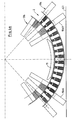
- FIGs 2 to 4 illustrate an inventive Execution of a transverse flux machine in one Partial section through the transverse flux machine in axial Direction with a so-called floor gap.
- the basic structure of the The transverse flux machine corresponds to one conventional, as described in Figure 1.
- For the same Elements are therefore the same reference numerals used.
- the partial cut is in the installation position Shown transverse flux machine, the level E1 the Level clarifies in which the drive shaft is arranged is.
- the rotor carries all poles in a known manner Polar body structures 4a and 4b, based on FIG. 1a, shown here, however, only 4a, thus remain in their Structure unchanged.
- flattening takes place the transverse flux machine, viewed in the installation position, in Close to the ground.
- the outer stator 13a in radial direction outside the pole body structure 4a Stator soft iron elements omitted, i.e.
- stator soft iron elements are such that at least one area 20 (gap) on the outer stator 13a a larger space than that caused by the division between two neighboring ones Stator soft iron elements, here the Stator soft iron elements 10a1 and 10a2 arise.
- the outer stator 13a is free of Armature windings.
- the outer stator 13a thus experiences in Floor area one in terms of magnetic Properties effective interruption that is bilateral compared to a vertical V in the installation position, for example viewed over an angle ⁇ 1. In this Then there is no overlap of anchor and area Excitation field instead, because the magnetic paths for this absence.
- This offers the advantage that compared to the Use of a conventional transverse flux machine for Available space, which is the distance between corresponds to the two levels E1 and E3, almost completely can be used for the rotor. This results a larger-sized transverse flux machine, which can produce higher powers.
- Figure 2 illustrates, however, in addition to the invention Bottom gap a number of other advantageous Design options.
- Stator soft iron elements 10a1 and 10a2 i.e. Pole shoes of the External stator 13a from their orthogonal to the air gap 11a Swivel axis OH by an angle ⁇ 2.
- pole pieces 10a1 and 10a2 with a smaller iron width than that of the rotor.
- the stator soft iron element 10a2 has bevelled edges 21.
- the skin effect in the conductors due to the rotor field can be cranked. So that becomes a increased distance between the conductors, i.e. the individual Components of the armature winding, achieved by rotor 1 and the Influencing the armature winding by the rotor 1 decreased.
- FIG. 4a illustrates one possibility of directing the Rotor field by in the area of the gap on the inner stator 13b a Flußleit Sharing 15, which for example made of sheet metal Transformer iron or from a powder composite can be made to guide the rotor field is arranged.
- the Flußleit Sharing 15 is in the essentially in the area of the outer circumference of the inner stator 13b arranged.
- the windings are routed normally.
- On the representation of the windings that run cranked can be on the inner stator 13b in the area of extension Gap 20 was made clear for reasons of clarity Not shown.
- FIG. 4b shown to prevent intrusion of the Rotor stray field in the housing parts in the area of Inner diameter of the outer stator 13a in the area of Bottom gap a thin-walled screen 16 made of similar Materials are used.
- FIGs 5a and 5b is the use of an axial Flußleit Swisses 17 illustrates schematically.
- a flux guide 17 is radial at the level of the gap or the enlarged space 20 between two neighboring ones Stator soft iron elements, here the Stator soft iron elements 10a5 and 10a6, arranged.
- FIG. 5b illustrates this in a view III accordingly
- Figure 5a is a plan view of a pole structure 4 of a Rotor 1 of a transverse flux machine. it becomes can be seen that the axial flux guide to Guarantee of the intended function only in one very close to one another, the pole structure 4 assigned end ring 8 may be arranged.
Landscapes
- Engineering & Computer Science (AREA)
- Power Engineering (AREA)
- Iron Core Of Rotating Electric Machines (AREA)
- Auxiliary Drives, Propulsion Controls, And Safety Devices (AREA)
- Vehicle Interior And Exterior Ornaments, Soundproofing, And Insulation (AREA)
- Chutes (AREA)
- Permanent Magnet Type Synchronous Machine (AREA)
Claims (13)
- Machine à flux transversal comprenant1.1 un stator extérieur (13a), comportant de multiples éléments de stator extérieur en fer doux (10a) qui sont disposés essentiellement avec un pas uniforme de l'un à l'autre,1.2 un stator intérieur (13b), comportant de multiples éléments de stator intérieur en fer doux (10b),1.3 le stator intérieur (13b) comportant au moins un enroulement d'induit (12), et1.4 un rotor (1) qui est constitué - vu suivant une coupe perpendiculaire à l'axe - d'aimants (5) et d'éléments en fer doux (6) alternant entre eux,
caractérisée par les particularités suivantes :1.5 le stator extérieur (13a) est dépourvu d'enroulements d'induit,1.6 les éléments de stator extérieur en fer doux (10a) sont disposés de façon que, sur le stator extérieur (13a), il soit prévu au moins une zone (lacune) (20) comportant un espace intermédiaire, plus grand que cela n'est rendu nécessaire par le pas, entre deux éléments de stator en fer doux voisins l'un de l'autre, et1.7 des moyens servant à la compensation d'effets d'extrémité magnétiques sont associés, au moins indirectement, à ladite zone (20). - Machine à flux transversal suivant la revendication 1, caractérisée en ce que ladite zone est réalisée au moyen du basculement, dans des sens opposés, d'au moins deux éléments de stator extérieur en fer doux voisins l'un de l'autre à partir de leur position perpendiculaire (OH) par rapport à un entrefer formé entre le rotor (1) et le stator (13).
- Machine à flux transversal suivant la revendication 2, caractérisée en ce qu'au moins les éléments de stator en fer doux (10a1, 10a2) directement voisins de ladite zone (20) ont une épaisseur plus faible.
- Machine à flux transversal suivant la revendication 1, caractérisée en ce que ladite zone (20) est réalisée au moyen de l'absence d'au moins un élément de stator extérieur en fer doux.
- Machine à flux transversal suivant la revendication 4, caractérisée en ce qu'au moins les éléments de stator extérieur en fer doux (10a1, 10a2) voisins de ladite zone (20) présentent un basculement à partir de leur position (OH) perpendiculaire à l'entrefer.
- Machine à flux transversal suivant l'une des revendications 4 ou 5, caractérisée en ce qu'au moins les éléments de stator en fer doux directement voisins de ladite zone (20) ont une épaisseur plus faible.
- Machine à flux transversal suivant l'une des revendications 1 à 6, caractérisée en ce que l'enroulement d'induit (12) du stator intérieur (13b) est réalisé d'une manière coudée au moins dans une partie d'une zone qui peut être décrite sur le stator intérieur par un angle d'extension qui est égal à celui de la lacune suivant la direction circonférentielle du stator extérieur.
- Machine à flux transversal suivant l'une des revendications 1 à 7, caractérisée en ce que, sur le stator extérieur, au moins une pièce conduisant le flux (15, 17) est associée, au moins indirectement, à la zone comportant un espace intermédiaire, plus grand que cela n'est rendu nécessaire par le pas, entre deux éléments de stator en fer doux voisins l'un de l'autre.
- Machine à flux transversal suivant la revendication 8, caractérisée en ce que la pièce conduisant le flux (15) est disposée entre l'enroulement d'induit (12) du stator intérieur (13b) et le rotor (1).
- Machine à flux transversal suivant la revendication 8 ou 9, caractérisée en ce que la pièce conduisant le flux (17) est disposée à une faible distance suivant la direction axiale à côté du rotor.
- Machine à flux transversal suivant la revendication 8 ou 9, caractérisée en ce qu'un écran (16) est disposé en direction radiale sur la périphérie extérieure du rotor dans la zone de la lacune (20).
- Machine à flux transversal suivant l'une des revendications 8 à 11, caractérisée en ce que la pièce conduisant le flux (15, 17) est en fer pour transformateur feuilleté.
- Machine à flux transversal suivant l'une des revendications 8 à 11, caractérisée en ce que la pièce conduisant le flux (15, 17) est en une matière composite en poudre.
Applications Claiming Priority (2)
| Application Number | Priority Date | Filing Date | Title |
|---|---|---|---|
| DE19522382A DE19522382C1 (de) | 1995-06-23 | 1995-06-23 | Transversalflußmaschine zum Einsatz in einem Direktantrieb für Fahrzeuge, insbesondere Bahnantrieb |
| DE19522382 | 1995-06-23 |
Publications (2)
| Publication Number | Publication Date |
|---|---|
| EP0749877A1 EP0749877A1 (fr) | 1996-12-27 |
| EP0749877B1 true EP0749877B1 (fr) | 1998-03-25 |
Family
ID=7764793
Family Applications (1)
| Application Number | Title | Priority Date | Filing Date |
|---|---|---|---|
| EP96108378A Expired - Lifetime EP0749877B1 (fr) | 1995-06-23 | 1996-05-25 | Machine à flux transversal pour l'emploi dans un entraínement direct de véhicule, en particulier l'entraínement d'un chemin de fer |
Country Status (5)
| Country | Link |
|---|---|
| US (1) | US5777418A (fr) |
| EP (1) | EP0749877B1 (fr) |
| JP (1) | JPH09149610A (fr) |
| AT (1) | ATE164354T1 (fr) |
| DE (2) | DE19522382C1 (fr) |
Cited By (1)
| Publication number | Priority date | Publication date | Assignee | Title |
|---|---|---|---|---|
| DE102011089985A1 (de) | 2011-12-27 | 2013-06-27 | Bayerische Motoren Werke Aktiengesellschaft | Verfahren zur Herstellung eines Rotors einer Transversalflussmaschine |
Families Citing this family (27)
| Publication number | Priority date | Publication date | Assignee | Title |
|---|---|---|---|---|
| DE19704392A1 (de) * | 1997-02-06 | 1998-08-13 | Voith Turbo Kg | Verwendung einer Transversalflußmaschine zum Einsatz in einem Einzelradantrieb für Fahrzeuge und Einzelradantrieb für Fahrzeuge |
| US6384496B1 (en) | 1999-05-17 | 2002-05-07 | Wavecrest Laboratories, Llc | Multiple magnetic path electric motor |
| SE521607C2 (sv) * | 2000-04-07 | 2003-11-18 | Abb Ab | En linjär elektrisk maskin |
| US6952068B2 (en) * | 2000-12-18 | 2005-10-04 | Otis Elevator Company | Fabricated components of transverse flux electric motors |
| US6664704B2 (en) * | 2001-11-23 | 2003-12-16 | David Gregory Calley | Electrical machine |
| US20040021437A1 (en) * | 2002-07-31 | 2004-02-05 | Maslov Boris A. | Adaptive electric motors and generators providing improved performance and efficiency |
| US20050127856A1 (en) * | 2002-07-31 | 2005-06-16 | Wavecrest Laboratories | Low-voltage electric motors |
| US20050046375A1 (en) * | 2002-07-31 | 2005-03-03 | Maslov Boris A. | Software-based adaptive control system for electric motors and generators |
| US20040263099A1 (en) * | 2002-07-31 | 2004-12-30 | Maslov Boris A | Electric propulsion system |
| US20050045392A1 (en) * | 2002-07-31 | 2005-03-03 | Maslov Boris A. | In-wheel electric motors |
| DE102005030616B3 (de) * | 2005-06-30 | 2007-02-15 | Michels, Klaus, Prof. Dr. | Elektrische Maschine nach dem Reluktanzprinzip |
| WO2008141245A2 (fr) * | 2007-05-09 | 2008-11-20 | Motor Excellence, Llc | Dispositifs de génération de sortie électrique et dispositifs électriques entraînés présentant des éléments de rotor ou de stator stratifiés à tore enroulé et leurs procédés de fabrication et d'utilisation |
| US7868511B2 (en) * | 2007-05-09 | 2011-01-11 | Motor Excellence, Llc | Electrical devices using disk and non-disk shaped rotors |
| BRPI0813185B1 (pt) | 2007-07-09 | 2023-12-19 | Clearwater Holdings, Ltd | Máquina eletromagnética giratória |
| US7830057B2 (en) * | 2008-08-29 | 2010-11-09 | Hamilton Sundstrand Corporation | Transverse flux machine |
| EP2340602B1 (fr) | 2008-09-26 | 2019-01-02 | Clearwater Holdings, Ltd. | Machine motrice à aimants permanents |
| US7923886B2 (en) | 2008-11-03 | 2011-04-12 | Motor Excellence, Llc | Transverse and/or commutated flux system rotor concepts |
| WO2011115632A1 (fr) | 2010-03-15 | 2011-09-22 | Motor Excellence Llc | Systèmes à flux transversal et/ou à flux commuté, configurés de façon à réduire les déperditions de flux, à réduire les déperditions d'hystérésis et à réaliser une adaptation de phase |
| DK2548289T3 (da) * | 2010-03-15 | 2020-02-17 | Motor Excellence Llc | Tværgående og/eller kommuterede strømningssystemer med faseforskydning |
| CN102986115A (zh) | 2010-03-15 | 2013-03-20 | 电扭矩机器股份有限公司 | 用于电动自行车的横向和/或换向通量系统 |
| WO2012067895A2 (fr) | 2010-11-17 | 2012-05-24 | Motor Excellence, Llc | Concepts de bobine de système à flux transversal et/ou commuté |
| EP2641316B1 (fr) | 2010-11-17 | 2019-02-13 | Motor Excellence, LLC | Systèmes à flux commuté et/ou transversal comprenant des tôles de stator segmentées |
| WO2012067896A2 (fr) | 2010-11-17 | 2012-05-24 | Motor Excellence, Llc | Systèmes à flux commuté et/ou transversal comprenant des tôles de stator segmentées et en poudre |
| US10505412B2 (en) | 2013-01-24 | 2019-12-10 | Clearwater Holdings, Ltd. | Flux machine |
| ES2746566T3 (es) * | 2016-04-26 | 2020-03-06 | Abb Schweiz Ag | Máquina eléctrica giratoria de doble estátor |
| JP7052017B2 (ja) | 2017-09-08 | 2022-04-11 | クリアウォーター ホールディングス,リミテッド | 蓄電を改善するシステム及び方法 |
| WO2019084568A1 (fr) | 2017-10-29 | 2019-05-02 | Clearwater Holdings, Ltd. | Machines électromagnétiques modulaires et leurs procédés d'utilisation et de fabrication |
Family Cites Families (12)
| Publication number | Priority date | Publication date | Assignee | Title |
|---|---|---|---|---|
| FR568856A (fr) * | 1923-04-11 | 1924-04-03 | Electricite Ganz Sa D | Moteur pour chemins de fer électriques |
| DE3536538A1 (de) * | 1985-10-12 | 1987-04-23 | Weh Herbert | Transversalfluss-maschine mit permanenterregung |
| US5233252A (en) * | 1985-11-20 | 1993-08-03 | Allied-Signal | Motor having integral detent |
| DE3705089A1 (de) * | 1987-02-13 | 1988-08-25 | Weh Herbert | Transversalflussmaschine in sammleranordnung |
| DE3904516C1 (fr) * | 1989-02-15 | 1990-06-13 | Robert Bosch Gmbh, 7000 Stuttgart, De | |
| DE3927311A1 (de) * | 1989-08-18 | 1991-02-21 | Magnet Motor Gmbh | Elektromotorischer schienenfahrzeug-direktantrieb |
| SE463061B (sv) * | 1989-11-20 | 1990-10-01 | Svante Gustav Adolf Von Zweygb | Permanentmagnetiserad synkronmaskin utformad enligt transversalfloedesprincipen |
| IT1244276B (it) * | 1990-07-03 | 1994-07-08 | Elettromeccanica Parizzi Spa | Gruppo ruota-motore elettrico per carrelli di veicoli ferrotranviari |
| ES2070515T3 (es) * | 1990-11-23 | 1995-06-01 | Voith Gmbh J M | Maquina electrica. |
| TW212240B (fr) * | 1991-03-19 | 1993-09-01 | Hitachi Seisakusyo Kk | |
| JP3152405B2 (ja) * | 1992-06-10 | 2001-04-03 | オークマ株式会社 | 電動機 |
| DE4314513C2 (de) * | 1993-05-03 | 1995-11-16 | Weh Herbert | Transversalflußmaschine mit kombinierter Permanentmagnet-Erregung |
-
1995
- 1995-06-23 DE DE19522382A patent/DE19522382C1/de not_active Expired - Fee Related
-
1996
- 1996-05-25 EP EP96108378A patent/EP0749877B1/fr not_active Expired - Lifetime
- 1996-05-25 DE DE59600123T patent/DE59600123D1/de not_active Expired - Lifetime
- 1996-05-25 AT AT96108378T patent/ATE164354T1/de active
- 1996-06-17 US US08/664,826 patent/US5777418A/en not_active Expired - Lifetime
- 1996-06-24 JP JP8163022A patent/JPH09149610A/ja active Pending
Cited By (2)
| Publication number | Priority date | Publication date | Assignee | Title |
|---|---|---|---|---|
| DE102011089985A1 (de) | 2011-12-27 | 2013-06-27 | Bayerische Motoren Werke Aktiengesellschaft | Verfahren zur Herstellung eines Rotors einer Transversalflussmaschine |
| DE102011089985B4 (de) * | 2011-12-27 | 2025-12-24 | Bayerische Motoren Werke Aktiengesellschaft | Verfahren zur Herstellung eines Rotors einer Transversalflussmaschine |
Also Published As
| Publication number | Publication date |
|---|---|
| ATE164354T1 (de) | 1998-04-15 |
| US5777418A (en) | 1998-07-07 |
| DE19522382C1 (de) | 1996-12-19 |
| JPH09149610A (ja) | 1997-06-06 |
| DE59600123D1 (de) | 1998-04-30 |
| EP0749877A1 (fr) | 1996-12-27 |
Similar Documents
| Publication | Publication Date | Title |
|---|---|---|
| EP0749877B1 (fr) | Machine à flux transversal pour l'emploi dans un entraínement direct de véhicule, en particulier l'entraínement d'un chemin de fer | |
| DE69524380T2 (de) | Elektromotor mit axialem fluss und offenem stator | |
| DE69310714T2 (de) | Elektromotorische leichtgewichtsvorrichtung von hoher leistung | |
| EP1759447B1 (fr) | Machine a champ tournant pourvue d'induits en cloche | |
| DE60031196T2 (de) | Statoraufbau eines Motors | |
| WO2015120959A1 (fr) | Aéronef équipé d'une machine synchrone à réluctance | |
| DE102009038928A1 (de) | Elektromotor | |
| DE3313747C2 (de) | Elektrische Maschine | |
| EP0858149B1 (fr) | Entraínement d'une roue d'un véhicule | |
| WO2020207861A1 (fr) | Dent de stator présentant une géométrie de dent asymétrique | |
| CH659552A5 (de) | Rotor fuer elektrische rotationsmaschine. | |
| DE19704769C2 (de) | Mehrsträngige Synchronmaschine mit Permanentmagneten und Spulenmodulen | |
| DE102019206081B3 (de) | Lüfter für ein Steuergerät für ein Fahrzeug und Steuergerät mit einem Lüfter | |
| DE102021106341A1 (de) | Elektromotor mit verbesserter Motorausnutzung | |
| DE102020107990A1 (de) | Manipulatorarm für einen Roboter sowie Roboter mit einem solchen Manipulatorarm | |
| DE19960182A1 (de) | Elektrische Maschine | |
| EP3457529B1 (fr) | Moteur à induit en disque | |
| DE10303183A1 (de) | Wirbelstromkupplung sowie Lüfterkupplung mit einer Wirbelstromkupplung | |
| DE102017123332A1 (de) | Elektromaschine mit segmentiertem Stator und Elektromaschinensystem | |
| DE102021132325A1 (de) | Stator für eine axialflussmaschine | |
| DE102021211629A1 (de) | Rotor für eine fremderregte elektrische Maschine, elektrische Maschine und Kraftfahrzeug | |
| DE3145804C2 (de) | Rotor für einen Turbogenerator | |
| DE9114582U1 (de) | Elektrische Maschine | |
| WO2023174483A1 (fr) | Stator d'une machine tournante électrique, machine tournante électrique et unité motrice à engrenages | |
| EP2683062A2 (fr) | Moteur couple à angle limité pour l'actionnement d'une soupape de commande hydraulique dans un aéronef |
Legal Events
| Date | Code | Title | Description |
|---|---|---|---|
| PUAI | Public reference made under article 153(3) epc to a published international application that has entered the european phase |
Free format text: ORIGINAL CODE: 0009012 |
|
| AK | Designated contracting states |
Kind code of ref document: A1 Designated state(s): AT DE FR GB IT SE |
|
| 17P | Request for examination filed |
Effective date: 19970415 |
|
| GRAG | Despatch of communication of intention to grant |
Free format text: ORIGINAL CODE: EPIDOS AGRA |
|
| GRAG | Despatch of communication of intention to grant |
Free format text: ORIGINAL CODE: EPIDOS AGRA |
|
| GRAH | Despatch of communication of intention to grant a patent |
Free format text: ORIGINAL CODE: EPIDOS IGRA |
|
| 17Q | First examination report despatched |
Effective date: 19970807 |
|
| GRAH | Despatch of communication of intention to grant a patent |
Free format text: ORIGINAL CODE: EPIDOS IGRA |
|
| GRAA | (expected) grant |
Free format text: ORIGINAL CODE: 0009210 |
|
| AK | Designated contracting states |
Kind code of ref document: B1 Designated state(s): AT DE FR GB IT SE |
|
| REF | Corresponds to: |
Ref document number: 164354 Country of ref document: AT Date of ref document: 19980415 Kind code of ref document: T |
|
| GBT | Gb: translation of ep patent filed (gb section 77(6)(a)/1977) |
Effective date: 19980326 |
|
| REF | Corresponds to: |
Ref document number: 59600123 Country of ref document: DE Date of ref document: 19980430 |
|
| ET | Fr: translation filed | ||
| ITF | It: translation for a ep patent filed | ||
| PLBE | No opposition filed within time limit |
Free format text: ORIGINAL CODE: 0009261 |
|
| STAA | Information on the status of an ep patent application or granted ep patent |
Free format text: STATUS: NO OPPOSITION FILED WITHIN TIME LIMIT |
|
| 26N | No opposition filed | ||
| REG | Reference to a national code |
Ref country code: GB Ref legal event code: IF02 |
|
| PGFP | Annual fee paid to national office [announced via postgrant information from national office to epo] |
Ref country code: FR Payment date: 20110607 Year of fee payment: 16 Ref country code: SE Payment date: 20110524 Year of fee payment: 16 |
|
| PGFP | Annual fee paid to national office [announced via postgrant information from national office to epo] |
Ref country code: GB Payment date: 20110525 Year of fee payment: 16 Ref country code: AT Payment date: 20110526 Year of fee payment: 16 |
|
| PGFP | Annual fee paid to national office [announced via postgrant information from national office to epo] |
Ref country code: DE Payment date: 20110601 Year of fee payment: 16 Ref country code: IT Payment date: 20110523 Year of fee payment: 16 |
|
| REG | Reference to a national code |
Ref country code: SE Ref legal event code: EUG |
|
| REG | Reference to a national code |
Ref country code: AT Ref legal event code: MM01 Ref document number: 164354 Country of ref document: AT Kind code of ref document: T Effective date: 20120525 |
|
| GBPC | Gb: european patent ceased through non-payment of renewal fee |
Effective date: 20120525 |
|
| PG25 | Lapsed in a contracting state [announced via postgrant information from national office to epo] |
Ref country code: AT Free format text: LAPSE BECAUSE OF NON-PAYMENT OF DUE FEES Effective date: 20120525 |
|
| PG25 | Lapsed in a contracting state [announced via postgrant information from national office to epo] |
Ref country code: IT Free format text: LAPSE BECAUSE OF NON-PAYMENT OF DUE FEES Effective date: 20120525 Ref country code: SE Free format text: LAPSE BECAUSE OF NON-PAYMENT OF DUE FEES Effective date: 20120526 |
|
| REG | Reference to a national code |
Ref country code: FR Ref legal event code: ST Effective date: 20130131 |
|
| REG | Reference to a national code |
Ref country code: DE Ref legal event code: R119 Ref document number: 59600123 Country of ref document: DE Effective date: 20121201 |
|
| PG25 | Lapsed in a contracting state [announced via postgrant information from national office to epo] |
Ref country code: GB Free format text: LAPSE BECAUSE OF NON-PAYMENT OF DUE FEES Effective date: 20120525 Ref country code: FR Free format text: LAPSE BECAUSE OF NON-PAYMENT OF DUE FEES Effective date: 20120531 |
|
| PG25 | Lapsed in a contracting state [announced via postgrant information from national office to epo] |
Ref country code: DE Free format text: LAPSE BECAUSE OF NON-PAYMENT OF DUE FEES Effective date: 20121201 |