EP0749928B1 - Falzzylinder - Google Patents
Falzzylinder Download PDFInfo
- Publication number
- EP0749928B1 EP0749928B1 EP96108996A EP96108996A EP0749928B1 EP 0749928 B1 EP0749928 B1 EP 0749928B1 EP 96108996 A EP96108996 A EP 96108996A EP 96108996 A EP96108996 A EP 96108996A EP 0749928 B1 EP0749928 B1 EP 0749928B1
- Authority
- EP
- European Patent Office
- Prior art keywords
- spindle
- folding cylinder
- folding
- cylinder according
- adjustment
- Prior art date
- Legal status (The legal status is an assumption and is not a legal conclusion. Google has not performed a legal analysis and makes no representation as to the accuracy of the status listed.)
- Expired - Lifetime
Links
- 230000007246 mechanism Effects 0.000 claims description 6
- 230000033001 locomotion Effects 0.000 description 3
- 230000005540 biological transmission Effects 0.000 description 1
- 238000006073 displacement reaction Methods 0.000 description 1
- 230000002349 favourable effect Effects 0.000 description 1
Images


Classifications
-
- B—PERFORMING OPERATIONS; TRANSPORTING
- B65—CONVEYING; PACKING; STORING; HANDLING THIN OR FILAMENTARY MATERIAL
- B65H—HANDLING THIN OR FILAMENTARY MATERIAL, e.g. SHEETS, WEBS, CABLES
- B65H45/00—Folding thin material
- B65H45/12—Folding articles or webs with application of pressure to define or form crease lines
- B65H45/16—Rotary folders
- B65H45/162—Rotary folders with folding jaw cylinders
- B65H45/166—Rotary folders with folding jaw cylinders having an adjustable circumference
-
- B—PERFORMING OPERATIONS; TRANSPORTING
- B65—CONVEYING; PACKING; STORING; HANDLING THIN OR FILAMENTARY MATERIAL
- B65H—HANDLING THIN OR FILAMENTARY MATERIAL, e.g. SHEETS, WEBS, CABLES
- B65H45/00—Folding thin material
- B65H45/12—Folding articles or webs with application of pressure to define or form crease lines
- B65H45/16—Rotary folders
- B65H45/162—Rotary folders with folding jaw cylinders
- B65H45/167—Rotary folders with folding jaw cylinders having associated sheet guide means
Definitions
- the invention relates to a folding cylinder according to the preamble of claim 1.
- a folding cylinder with an adjustable one is known from DE 295 02 957.9 U1 Circumference, the shaft of the folding cylinder with a coaxial Bore is provided, in which a drivable adjusting spindle is arranged, mechanically transfer their rotary motion to axially parallel spindles is that with the circumference of the folding cylinder varying radially adjustable Support elements for the folded products is coupled.
- a folding cylinder according to the preamble of claim 1 is known from DE-A-2309919.
- the invention has for its object a folding cylinder according to the Generic preamble of claim 1 to create that with inexpensive, simple Means an adjustment of the mechanisms while the machine is running guaranteed.
- the subclaims contain in particular with regard to the traction device, the Adjustment of the mechanisms in the form of folding jaws or the scope of the folding cylinder changeable support elements, the arrangement of the with Mechanisms connected spindle and the axial adjustment of the adjusting spindle favorable embodiments of the solution principle.
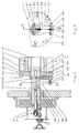
- Fig. 1 shows a folding cylinder 1 whose circumference by means of radially adjustable Support elements 2; 3 is changeable for the folding products, not shown.
- a is in a coaxial bore 4 of the shaft 5 of the folding cylinder 1
- Adjusting spindle 6 can be actuated by an outside of the machine casing Actuator 7 axially adjustable.
- a recess 8 of the adjusting spindle 6 are coaxial thereon spaced apart by a bolt 9; 10 the ends of a traction device in Shape of a chain 11 attached, the two converging Dreams 12; 13 each by a in a radial opening 14; 15 of the Bore 4 on an eccentric pin 16; 17 mounted deflection plate 18; 19 90 ° deflected with the interposition of a 90 ° angle offset one toothed, on an axis parallel to the shaft 5 in the fixed to this Cylinder body 20 mounted spindle 21 attached drive pulley 22 lead and embrace them.
- the spindle 21 has an eccentric pin 23 at its ends; 24, the one in the front of the folding cylinder 1 delimiting, rotatable on the Shaft 5 arranged disc 25; 26 positively in their direction of rotation intervention.
- the disks 25; 26 are inclined to the respective radial Slots 27; 28 equipped (Fig. 2), in each case radially positive a pin 29 to 32 in the cylinder body 20 axially parallel radially displaceable guided, along the cylinder body 20 several times with support elements 2; 3 equipped crossbeam 33; 34 engages (Fig. 1).
- a guide pin 38 is mounted axially fixed in the bearing housing 35 a link 39 is articulated, one of an axially parallel to the adjusting spindle 6 in the frame 40; 40 'mounted threaded spindle 41 penetrated Has threaded hole.
- the threaded spindle also engages another thread of opposite pitch, d. H. with a Right or left-hand thread in a corresponding threaded hole in a on the frame 40 attached guide piece 42. Outside the frame 40 ', the threaded spindle 41 is opposed by means of a clamping device 43 Lockable rotation and equipped with an operating element 44.
- Fig. 3 shows one of two rotatably arranged on the shaft 5 'with each jaws of the same type as fixed jaws 45 or movable Counter-folding flaps 46 equipped cylinder parts 47; 48 existing folding cylinders 1 ', the fixed jaws 45 on the inside massive Cylinder part 47 attached and the counter-folding flaps 46 in about axial openings 49; 50 of the latter by means of trusses 51; 52 connected and washers 53; 54 are stored.
- FIGS. 4 and 5 show a folding cylinder 1 '' designed analogously to FIG. 3, whose fixed jaws 45 'bearing cylinder member 47' opposite the movable counter-folding flaps 46 'carrying the cylinder part 48', deviating to Fig. 3, with the help of a perpendicular to the adjusting spindle 6 '' Plane arranged spindle 62 is rotatable in one with the driver 61 'fixedly connected fork 63 twice, each with radial play is mounted and the drive pulley 64 between the two bearing points bears, due to the arrangement rotated by 90 ° relative to FIGS. 1 to 3 the angular displacement links in the chain 65 are omitted and the two Deflection disks 66; 67 in an axis parallel to the adjusting spindle 6 '' through recess 68 are arranged.
- the spindle 62 engages with threads arranged at its ends opposite, equal pitch in a threaded hole in a respective cylinder part 47 'or 48' rotatably mounted bolt 69; 70 a, the bolt 69 for the inner cylinder part 47 'the outer Washer 53 'of the other cylinder part 48' in a recess under one the mutual rotation of the cylinder parts 47 '; 48 'enabling Radial play penetrated.
- the traction means with the associated drive means depending on the respective design of the folding cylinder both inside as well as be arranged on the end face of this.
Landscapes
- Folding Of Thin Sheet-Like Materials, Special Discharging Devices, And Others (AREA)
Description
- Fig. 1:
- einen Längsschnitt eines Falzzylinders mit einer erfindungsgemäßen Verstellung dessen Stützelemente für die Falzprodukte während des Maschinenlaufes
- Fig. 2:
- einen Querschnitt gemäß Schnitt A-A von Fig. 1
- Fig. 3:
- einen Längsschnitt des Falzzylinders mit einer erfindungsgemäßen Verstellung dessen Falzklappen während des Maschinenlaufes
- Fig. 4:
- eine Variante von Fig. 3 mit anderer Spindelanordnung gemäß Schnitt D-D von Fig. 5
- Fig. 5:
- einen Querschnitt gemäß Schnitt C-C von Fig. 4
Claims (22)
- Falzzylinder (1) für Falzapparate von Rotationsdruckmaschinen mit verstellbaren Mechanismen - insbesondere mit den Umfang des Falzzylinders variierend verstellbaren Stützelementen (2, 3) für die Falzprodukte bzw. die Einstellung der Produktdicke ermöglichenden Verstellelementen für Falzklappen (45, 46, 45', 46') - die mit mindestens einer Spindel (21, 55, 62) in Wirkverbindung stehen, die im Falzzylinder (1) zu dessen Welle (5, 5', 5'') radial beabstandet angeordnet und mit Hilfe einer in einer koaxialen Bohrung der Welle angeordneten Stellspindel (6, 6',6'') verdrehbar ist, wobei die Stellspindel (6; 6'; 6'') gegenüber der Welle (5; 5'; 5'') gegen Verdrehung gesichert in deren Bohrung (4; 4'; 4'') axial verschiebbar angeordnet ist, gekennzeichnet dadurch, daß die Stellspindel den Enden mit eines Zugmittels axial beabstandet jeweils fest verbunden ist, dessen beide Trume (12; 12'; 12'', 13; 13'; 13'') aufeinander zulaufend jeweils über eine in einem radialen Durchbruch (14; 14'; 15; 15'; 68) der Bohrung (4; 4'; 4'') angeordnete Umlenkscheibe (18; 18'; 19; 19'; 66; 67) zu einer auf der Spindel (21; 55; 62) befestigten, von dem Zugmittel umschlungenen Antriebsscheibe (22; 22'; 64) führen.
- Falzzylinder nach Anspruch 1, gekennzeichnet dadurch, daß die Spindel (21; 55) zur Stellspindel (6; 6') achsparallel angeordnet ist.
- Falzzylinder nach Anspruch 1, gekennzeichnet dadurch, daß die Spindel (62) in einer senkrechten Ebene zur Stellspindel (6'') angeordnet ist.
- Falzzylinder nach Anspruch 1 bis 3, gekennzeichnet dadurch, daß zumindest die Antriebsscheibe (22; 22'; 64) verzahnt ist, das Zugmittel als Kette (11; 11'; 65) oder Zahnriemen ausgeführt ist und bei der zur Stellspindel (6; 6') achsparallelen Anordnung der Spindel (21; 55) die Trume (12; 12'; 13; 13') jeweils zwischen Umlenkscheibe (18; 18'; 19; 19') und Antriebsscheibe (22; 22') mit einem 90°-Winkelversatzglied ausgestattet sind.
- Falzzylinder nach Anspruch 1 bis 3, gekennzeichnet dadurch, daß das Zugmittel als Seil ausgeführt ist, das im Umschlingungsbereich der Antriebsscheibe (22; 22'; 64) an deren Umfang befestigt ist.
- Falzzylinder nach Anspruch 1, 2, 4 und 5, gekennzeichnet dadurch, daß die Umlenkscheiben (18; 18'; 19; 19') zueinander winklig in zwei verschiedenen, zur Welle (5; 5') achsparallel in Richtung des jeweiligen Trumes (12; 12'; 13; 13') liegenden Ebenen angeordnet sind.
- Falzzylinder nach Anspruch 1, 3 bis 5, gekennzeichnet dadurch, daß die Umlenkscheiben (66; 67) unter Belassung eines Zwischenraumes für die Trume (12''; 13''), das Zugmittel und die Antriebsscheibe (64) in einer zur Welle (5'') achsparallelen Ebene angeordnet sind.
- Falzzylinder nach Anspruch 1 bis 7, gekennzeichnet dadurch, daß die Umlenkscheiben (18; 18'; 19 19'; 66; 67) auf verstellbaren Exzenterbolzen (16; 16'; 16''; 17; 17'; 17'') gelagert sind.
- Falzzylinder nach Anspruch 1 bis 8, gekennzeichnet dadurch, daß das Zugmittel jeweils an einem radial in der Stellspindel (6; 6'; 6'') sitzenden Bolzen (9; 10) befestigt ist.
- Falzzylinder nach Anspruch 1 bis 9, gekennzeichnet dadurch, daß außerhalb der Bohrung (4; 4'; 4'') an der Stellspindel (6; 6'; 6'') stirnseitig ein Lagergehäuse (35) befestigt ist, das mit Hilfe eines zur Stellspindel (6; 6'; 6'') achsparallelen Führungsstiftes (37) gegenüber der Welle (5; 5'; 5'') verdrehgesichert ist.
- Falzzylinder nach Anspruch 10, gekennzeichnet dadurch, daß koaxial zur Stellspindel (6; 6'; 6'') in dem Lagergehäuse (35) axial fixiert ein Führungsbolzen (38) gelagert ist, an dem eine Axialverstellung der Stellspindel (6; 6'; 6'') bewirkende Mittel formschlüssig angreifen.
- Falzzylinder nach Anspruch 11, gekennzeichnet dadurch, daß an dem Führungsbolzen (38) ein Verbindungsstück (39) angelenkt ist, das unter Gewährleistung eines axial wirksamen Formschlusses in einer Bohrung von einer zur Stellspindel (6; 6'; 6'') achsparallel im Gestell (40; 40') gelagerten Gewindespindel (41) durchsetzt ist.
- Falzzylinder nach Anspruch 12, gekennzeichnet dadurch, daß die Gewindespindel (41) außerhalb des Gestelles (40; 40') mit einer Klemmeinrichtung (43) ausgestattet ist und ein Bedienelement (44) trägt.
- Falzzylinder nach Anspruch 1; 2; 4 bis 6; 8 bis 13, gekennzeichnet dadurch, daß die im Zylinderkörper (20) achsparallel gelagerte Spindel (21) beiderseitig des Zylinderkörpers (20) jeweils mit einem Exzenterzapfen (23; 24) formschlüssig in eine Aussparung einer verdrehbar auf der Welle des Falzzylinders angeordnete Scheibe (25; 26) eingreift, die zur jeweiligen Radiale schräg verlaufende Langlöcher (27; 28) besitzen, in die jeweils in radialer Richtung formschlüssig ein Zapfen (29 bis 32) einer im Zylinderkörper (20) achsparallel radial verschiebbar geführten, längs des Zylinderkörpers (20) mehrfach mit Stützelementen (2; 3) bestückten Traverse (33; 34) eingreift.
- Falzzylinder nach Anspruch 1; 2; 4 bis 6; 8 bis 13, gekennzeichnet dadurch, daß die mit mindestens einem exzentrischen Abschnitt (56) ausgestattete Spindel (55) mit jeweils einem Abschnitt (55; 56) in ein Zylinderteil (48; 47) von zwei mit jeweils Falzklappen gleicher Art als bewegliche Gegenfalzklappen (46) bzw. feste Falzklappen (45) bestückten, verdrehbar auf der Welle (5) angeordneten Zylinderteilen (47; 48) eingreift und mit einem dritten zentrischen Abschnitt (59) in einem mit der Welle (5') fest verbundenen Mitnehmer (61) geführt bzw. gelagert ist.
- Falzzylinder nach Anspruch 15, gekennzeichnet dadurch, daß die Spindel (60) an der Außenseite des Mitnehmers (61) die Antriebsscheibe (22') mit einem stirnseitig am Falzzylinder (1') verlaufenden Zugmittel trägt.
- Falzzylinder nach Anspruch 1; 3 bis 5; 7 bis 13, gekennzeichnet dadurch, daß die Spindel (62) stirnseitig am Falzzylinder (1'') in einer mit einem gegenüber dessen Welle (5'') verdrehfesten Mitnehmer (61') verbundenen Halterung gelagert und an ihren Enden mit Gewinde unterschiedlicher Steigung ausgestattet ist, mit dem sie jeweils in die Gewindebohrung eines mit einem verdrehbar auf der Welle (5'') angeordneten, mit Falzklappen gleicher Art als feste Falzklappen (45') bzw. bewegliche Gegenfalzklappen (46') bestückten Zylinderteil (47'; 48') verbundenen Zwischenstückes eine gegenseitige Verdrehung der Zylinderteile bewirkbar eingreift.
- Falzzylinder nach Anspruch 17, gekennzeichnet dadurch, daß die Halterung als eine der Zweifachlagerung der Spindel (62) unter Gewährleistung eines die gegenseitige Verdrehung der Zylinderteile (47'; 48') ermöglichenden Radialspieles dienende, zwischen ihren Schenkeln die Antriebsscheibe (64) aufnehmende Gabel (63) ausgebildet ist.
- Falzzylinder nach Anspruch 17 und 18, gekennzeichnet dadurch, daß das Zwischenstück als ein verdrehbar im jeweiligen Zylinderteil (47'; 48') gelagerter, mit einer radialen Gewindebohrung für die Spindel (62) ausgestatteter Bolzen (69; 70) ausgeführt ist.
- Falzzylinder nach Anspruch 17 bis 19, gekennzeichnet dadurch, daß die Steigung der Gewinde an den Enden der Spindel (62) entgegengesetzt, gleich groß ist.
- Falzzylinder nach Anspruch 1 bis 20, gekennzeichnet dadurch, daß mehrere Spindeln jeweils getrennt mit der Stellspindel in (6, 6', 6'') Antriebsverbindung stehen, wobei die jeweils aus Zugmittel, Umlenkscheiben und Antriebsscheibe bestehenden Antriebssysteme zur Verstellspindel axial versetzt angeordnet sind.
- Falzzylinder nach Anspruch 1; 2; 4 bis 6; 8 bis 16, gekennzeichnet dadurch, daß mehrere zur Stellspindel (6, 6', 6'') achsparallele Spindeln jeweils über eine Antriebsscheibe durch ein in einer senkrechten Ebene verlaufendes, endloses Zugmittel untereinander und über eine ihre Spindeln mit dem aus Antriebsscheibe, Zugmittel und Umlenkscheiben bestehenden Antriebssystem mit der Stellspindel (6, 6', 6'') in Wirverbindung stehen.
Applications Claiming Priority (2)
| Application Number | Priority Date | Filing Date | Title |
|---|---|---|---|
| DE19522903 | 1995-06-23 | ||
| DE19522903A DE19522903A1 (de) | 1995-06-23 | 1995-06-23 | Falzzylinder |
Publications (2)
| Publication Number | Publication Date |
|---|---|
| EP0749928A1 EP0749928A1 (de) | 1996-12-27 |
| EP0749928B1 true EP0749928B1 (de) | 1999-08-25 |
Family
ID=7765127
Family Applications (1)
| Application Number | Title | Priority Date | Filing Date |
|---|---|---|---|
| EP96108996A Expired - Lifetime EP0749928B1 (de) | 1995-06-23 | 1996-06-05 | Falzzylinder |
Country Status (3)
| Country | Link |
|---|---|
| US (1) | US5782464A (de) |
| EP (1) | EP0749928B1 (de) |
| DE (2) | DE19522903A1 (de) |
Families Citing this family (5)
| Publication number | Priority date | Publication date | Assignee | Title |
|---|---|---|---|---|
| US7338425B1 (en) | 2000-01-12 | 2008-03-04 | Goss International Americas, Inc. | Variable length cutting device |
| DE10220109B4 (de) * | 2002-05-04 | 2007-04-05 | Man Roland Druckmaschinen Ag | Antrieb für Expansions-Segmente zur Durchmesserverstellung am Falzzylinder |
| US7819791B1 (en) * | 2007-09-28 | 2010-10-26 | Packaging Equipment Inc. | Cartoner for cartons having concave sides |
| CN101580191B (zh) * | 2009-03-30 | 2011-11-09 | 长沙奥托印刷机械有限公司 | 用于混合式折页机输纸带的张紧装置 |
| CN115669755B (zh) * | 2022-11-02 | 2024-11-08 | 贵州新大农业发展有限公司 | 能防止跑茶揉捻机 |
Family Cites Families (8)
| Publication number | Priority date | Publication date | Assignee | Title |
|---|---|---|---|---|
| US2093233A (en) * | 1936-05-14 | 1937-09-14 | Duplex Printing Press Co | Rotary folding mechanism for printing presses |
| DE2011661B1 (de) * | 1970-03-12 | 1971-07-15 | Maschinenfabrik Augsburg Nuernberg Ag | Falzmesszylinder für Rotationsdruckma schinen |
| DE2309919A1 (de) * | 1973-02-28 | 1974-09-05 | Frankenthal Ag Albert | Nuten- und falzmesserzylinder an falzapparaten von rotationsdruckmaschinen |
| JPS6186368A (ja) * | 1984-10-02 | 1986-05-01 | Ikegai Gosu Kk | 印刷機の折り装置 |
| IT1227324B (it) * | 1988-07-29 | 1991-04-08 | Cerutti Spa Off Mec | Piegatrice perfezionata per segnature prodotte da una macchina da stampa. |
| DE3838314A1 (de) * | 1988-11-11 | 1990-05-17 | Koenig & Bauer Ag | Falzklappenzylinder fuer eine rollenrotationsdruckmaschine |
| DE4415620C2 (de) * | 1994-05-04 | 1999-11-25 | Roland Man Druckmasch | Falzklappenzylinder |
| DE29502957U1 (de) * | 1995-02-22 | 1995-04-06 | MAN Roland Druckmaschinen AG, 63075 Offenbach | Zylinder in einem Falzwerk mit vertellbarem Durchmesser |
-
1995
- 1995-06-23 DE DE19522903A patent/DE19522903A1/de not_active Withdrawn
-
1996
- 1996-06-05 EP EP96108996A patent/EP0749928B1/de not_active Expired - Lifetime
- 1996-06-05 DE DE59602851T patent/DE59602851D1/de not_active Expired - Lifetime
- 1996-06-24 US US08/668,914 patent/US5782464A/en not_active Expired - Lifetime
Also Published As
| Publication number | Publication date |
|---|---|
| DE59602851D1 (de) | 1999-09-30 |
| DE19522903A1 (de) | 1997-01-02 |
| US5782464A (en) | 1998-07-21 |
| EP0749928A1 (de) | 1996-12-27 |
Similar Documents
| Publication | Publication Date | Title |
|---|---|---|
| EP0999170A1 (de) | Greifersystem | |
| DE3532514C1 (de) | Antriebsvorrichtung fuer eine Drehsaeule,insbesondere zur Bewegung von Schwenktuerfluegeln an Kraftfahrzeugen | |
| DE3539371C2 (de) | ||
| EP1332306B1 (de) | Drehverstellvorrichtung | |
| EP0749928B1 (de) | Falzzylinder | |
| EP0502296B1 (de) | Lenksäule für Kraftfahrzeuge | |
| EP0734987B1 (de) | Antrieb für ein Falzmesser in einer Falztrommel | |
| EP1214239A1 (de) | Kippstiftmechanismus zum klemmen einer verstellbaren lenksäule | |
| CH673640A5 (de) | ||
| DE3875236T2 (de) | Exzentrisch einstellbare vorrichtung. | |
| CH678823A5 (de) | ||
| DE4129404A1 (de) | Querleim-vorrichtung zum aufbringen von leim auf eine bewegte materialbahn | |
| EP1226372B1 (de) | Möbelantrieb | |
| CH623013A5 (en) | Folding-flap cylinder | |
| EP4051528B1 (de) | Getriebeanordnung für eine spindelantriebsanordnung, spindelantriebsanordnung und fahrzeugsitz | |
| DE3831182A1 (de) | Sammelzylinder fuer punkturfalzapparate von rotationsdruckmaschinen | |
| EP0810972A1 (de) | Changiervorrichtung | |
| DE4312835C2 (de) | Homogenisiereinrichtung oder dergleichen | |
| EP2695799B1 (de) | Pendel-/knickgelenkte Baumaschine | |
| DE3303302C2 (de) | Vorrichtung für den Antrieb eines Stellmittels für die Seitenkorrektur einer durchlaufenden Warenbahn | |
| DE4415620C2 (de) | Falzklappenzylinder | |
| DE19818254C1 (de) | Teilapparat | |
| DE3805971C2 (de) | ||
| DE4018819A1 (de) | Gelenkbeschlag fuer sitze mit verstellbarer rueckenlehne | |
| EP0496967B1 (de) | Spanneinrichtung an Werkzeugmaschinen mit einem umlaufenden Spannzylinder |
Legal Events
| Date | Code | Title | Description |
|---|---|---|---|
| PUAI | Public reference made under article 153(3) epc to a published international application that has entered the european phase |
Free format text: ORIGINAL CODE: 0009012 |
|
| AK | Designated contracting states |
Kind code of ref document: A1 Designated state(s): CH DE FR GB LI SE |
|
| 17P | Request for examination filed |
Effective date: 19970610 |
|
| GRAG | Despatch of communication of intention to grant |
Free format text: ORIGINAL CODE: EPIDOS AGRA |
|
| 17Q | First examination report despatched |
Effective date: 19980708 |
|
| GRAG | Despatch of communication of intention to grant |
Free format text: ORIGINAL CODE: EPIDOS AGRA |
|
| GRAH | Despatch of communication of intention to grant a patent |
Free format text: ORIGINAL CODE: EPIDOS IGRA |
|
| GRAH | Despatch of communication of intention to grant a patent |
Free format text: ORIGINAL CODE: EPIDOS IGRA |
|
| GRAA | (expected) grant |
Free format text: ORIGINAL CODE: 0009210 |
|
| AK | Designated contracting states |
Kind code of ref document: B1 Designated state(s): CH DE FR GB LI SE |
|
| REG | Reference to a national code |
Ref country code: CH Ref legal event code: NV Representative=s name: E. BLUM & CO. PATENTANWAELTE Ref country code: CH Ref legal event code: EP |
|
| REF | Corresponds to: |
Ref document number: 59602851 Country of ref document: DE Date of ref document: 19990930 |
|
| ET | Fr: translation filed | ||
| GBT | Gb: translation of ep patent filed (gb section 77(6)(a)/1977) |
Effective date: 19991129 |
|
| PLBE | No opposition filed within time limit |
Free format text: ORIGINAL CODE: 0009261 |
|
| STAA | Information on the status of an ep patent application or granted ep patent |
Free format text: STATUS: NO OPPOSITION FILED WITHIN TIME LIMIT |
|
| 26N | No opposition filed | ||
| REG | Reference to a national code |
Ref country code: GB Ref legal event code: IF02 |
|
| REG | Reference to a national code |
Ref country code: CH Ref legal event code: PFA Owner name: MAN ROLAND DRUCKMASCHINEN AG Free format text: MAN ROLAND DRUCKMASCHINEN AG#POSTFACH 10 12 64#63012 OFFENBACH (DE) -TRANSFER TO- MAN ROLAND DRUCKMASCHINEN AG#POSTFACH 10 12 64#63012 OFFENBACH (DE) |
|
| REG | Reference to a national code |
Ref country code: CH Ref legal event code: PFA Owner name: MANROLAND AG Free format text: MAN ROLAND DRUCKMASCHINEN AG#POSTFACH 10 12 64#63012 OFFENBACH (DE) -TRANSFER TO- MANROLAND AG#MUEHLHEIMER STRA?E 341#63075 OFFENBACH (DE) |
|
| REG | Reference to a national code |
Ref country code: FR Ref legal event code: CD |
|
| PGFP | Annual fee paid to national office [announced via postgrant information from national office to epo] |
Ref country code: FR Payment date: 20110630 Year of fee payment: 16 Ref country code: SE Payment date: 20110613 Year of fee payment: 16 |
|
| PGFP | Annual fee paid to national office [announced via postgrant information from national office to epo] |
Ref country code: GB Payment date: 20110620 Year of fee payment: 16 |
|
| PGFP | Annual fee paid to national office [announced via postgrant information from national office to epo] |
Ref country code: CH Payment date: 20120622 Year of fee payment: 17 Ref country code: DE Payment date: 20120622 Year of fee payment: 17 |
|
| REG | Reference to a national code |
Ref country code: DE Ref legal event code: R081 Ref document number: 59602851 Country of ref document: DE Owner name: MANROLAND WEB SYSTEMS GMBH, DE Free format text: FORMER OWNER: MANROLAND AG, 63075 OFFENBACH, DE Effective date: 20120626 |
|
| REG | Reference to a national code |
Ref country code: SE Ref legal event code: EUG |
|
| GBPC | Gb: european patent ceased through non-payment of renewal fee |
Effective date: 20120605 |
|
| PG25 | Lapsed in a contracting state [announced via postgrant information from national office to epo] |
Ref country code: SE Free format text: LAPSE BECAUSE OF NON-PAYMENT OF DUE FEES Effective date: 20120606 |
|
| REG | Reference to a national code |
Ref country code: FR Ref legal event code: ST Effective date: 20130228 |
|
| PG25 | Lapsed in a contracting state [announced via postgrant information from national office to epo] |
Ref country code: FR Free format text: LAPSE BECAUSE OF NON-PAYMENT OF DUE FEES Effective date: 20120702 Ref country code: GB Free format text: LAPSE BECAUSE OF NON-PAYMENT OF DUE FEES Effective date: 20120605 |
|
| REG | Reference to a national code |
Ref country code: CH Ref legal event code: PL |
|
| REG | Reference to a national code |
Ref country code: DE Ref legal event code: R119 Ref document number: 59602851 Country of ref document: DE Effective date: 20140101 |
|
| PG25 | Lapsed in a contracting state [announced via postgrant information from national office to epo] |
Ref country code: CH Free format text: LAPSE BECAUSE OF NON-PAYMENT OF DUE FEES Effective date: 20130630 Ref country code: DE Free format text: LAPSE BECAUSE OF NON-PAYMENT OF DUE FEES Effective date: 20140101 Ref country code: LI Free format text: LAPSE BECAUSE OF NON-PAYMENT OF DUE FEES Effective date: 20130630 |