EP0750149A1 - Elément pour un raccord à manchon - Google Patents
Elément pour un raccord à manchon Download PDFInfo
- Publication number
- EP0750149A1 EP0750149A1 EP96109769A EP96109769A EP0750149A1 EP 0750149 A1 EP0750149 A1 EP 0750149A1 EP 96109769 A EP96109769 A EP 96109769A EP 96109769 A EP96109769 A EP 96109769A EP 0750149 A1 EP0750149 A1 EP 0750149A1
- Authority
- EP
- European Patent Office
- Prior art keywords
- lubricant
- component
- component according
- layer
- contact surface
- Prior art date
- Legal status (The legal status is an assumption and is not a legal conclusion. Google has not performed a legal analysis and makes no representation as to the accuracy of the status listed.)
- Withdrawn
Links
Images

Classifications
-
- F—MECHANICAL ENGINEERING; LIGHTING; HEATING; WEAPONS; BLASTING
- F16—ENGINEERING ELEMENTS AND UNITS; GENERAL MEASURES FOR PRODUCING AND MAINTAINING EFFECTIVE FUNCTIONING OF MACHINES OR INSTALLATIONS; THERMAL INSULATION IN GENERAL
- F16L—PIPES; JOINTS OR FITTINGS FOR PIPES; SUPPORTS FOR PIPES, CABLES OR PROTECTIVE TUBING; MEANS FOR THERMAL INSULATION IN GENERAL
- F16L21/00—Joints with sleeve or socket
- F16L21/02—Joints with sleeve or socket with elastic sealing rings between pipe and sleeve or between pipe and socket, e.g. with rolling or other prefabricated profiled rings
- F16L21/035—Joints with sleeve or socket with elastic sealing rings between pipe and sleeve or between pipe and socket, e.g. with rolling or other prefabricated profiled rings placed around the spigot end before connection
-
- F—MECHANICAL ENGINEERING; LIGHTING; HEATING; WEAPONS; BLASTING
- F16—ENGINEERING ELEMENTS AND UNITS; GENERAL MEASURES FOR PRODUCING AND MAINTAINING EFFECTIVE FUNCTIONING OF MACHINES OR INSTALLATIONS; THERMAL INSULATION IN GENERAL
- F16L—PIPES; JOINTS OR FITTINGS FOR PIPES; SUPPORTS FOR PIPES, CABLES OR PROTECTIVE TUBING; MEANS FOR THERMAL INSULATION IN GENERAL
- F16L21/00—Joints with sleeve or socket
- F16L21/02—Joints with sleeve or socket with elastic sealing rings between pipe and sleeve or between pipe and socket, e.g. with rolling or other prefabricated profiled rings
- F16L21/03—Joints with sleeve or socket with elastic sealing rings between pipe and sleeve or between pipe and socket, e.g. with rolling or other prefabricated profiled rings placed in the socket before connection
Definitions
- the invention relates to a component for a push-in joint with the features in the preamble of claim 1.
- a seal is known (DE 38 26 622 A1), to which a flag which can be turned in the plug-in direction when the pipes are plugged together is fastened and can be displaced over at least part of its length by a lubricant relative to the rest of the seal, the lubricant is formed by a firmly arranged, thin-walled lacquer or film-like layer.
- the lubricant must not only be arranged directly on the flag, but it can also be arranged on the surface of the seal facing it and, moreover, on those surfaces of the seal which are not in contact with the flag or come into contact or from others Let a lubricant prove to be appropriate.
- a seal is known (DE 42 29 609 A1), which is composed of an elastomer body and a coupling part which can be connected into the latter and which consists of an internally hollow sliding jacket and is, for example, tubular. A lubricant is contained in the interior of this sliding jacket and serves as a lubricant for the seal.
- the coupling part consists of solid material, which is almost entirely accommodated in the elastomer body, but leaving a cavity in which a lubricant is filled, which is pressed out when the two parts of the seal are pressed together and lubricates both sealing parts.
- Another known seal (EP 0 343 677 A1) is designed similarly. Here, a compression seal is held on one component, while a flattened hose filled with lubricant is provided on the other component in the area of the compression seal.
- a sealing ring is known (EP 0 556 545 A1), which is formed from an elastomer to which at least one lubricant is added, which is arranged in a position-changing manner within the mixing substance.
- Sealing rings are also known (DE 29 00 437 A1), which are provided on the outside with a lubricant or lubricant. Also known is a seal (DE 39 09 381 A1) which is composed of a sealing ring to be attached to one tube part and an associated band-shaped slide ring which is to be applied to the other tube part. There is a lubricant between the sealing ring and the sliding ring, by means of which the sliding ring can be displaced on the sealing ring.
- the mutually assigned surfaces of the sealing ring and the sliding ring are provided with this lubricant, which is, for example, a liquid or paste-like agent or consists of a firmly adhering, thin-walled lacquer or film-like coating.
- this lubricant is, for example, a liquid or paste-like agent or consists of a firmly adhering, thin-walled lacquer or film-like coating.
- the lubricant is located in areas between two surfaces of a sealing part sliding against one another, the lubricant being in each case part of the seal. All of these seals have the following disadvantages.
- the seals are very complicated to manufacture and therefore expensive. Depending on the viscosity and temperature, the lubricant flows away in an uncontrolled manner. With longer storage, the lubricant is no longer where it should be and should work.
- a component of the type mentioned at the outset has also been proposed, in which a lubricant is applied manually to the contact surface of the one component before two components are pushed together.
- the consistency of the lubricant is liquid to pasty and is e.g. brushed on.
- This method has the following disadvantages. Sources of error are predefined by manual activity. The wrong lubricant is often applied or the application of the latter is completely forgotten, especially since this takes time and is annoying. Sometimes the lubricant is applied, but not in the right place, e.g. directly on the seal, so that when the components are pushed together, the lubricant is then rubbed off the seal and the seal then slides along such a contact surface that carries no lubricant at all. In such cases, the seal often blocks when two components are pushed together. The result is an uncontrolled movement of the seal in the seal gap and jamming.
- the invention has for its object to provide a component of the type mentioned, with which the latter disadvantages are eliminated and which is easy to assemble and ensures that when joining two components, the at least one sealing device on a component on the associated Contact surface of the component slides along as easily as possible.
- the object is achieved in a component of the type mentioned according to the invention by the features in claim 1. Due to the fact that the lubricant is applied to the contact surface of the component, e.g. while it is being manufactured, it is e.g. a component with an integrated lubricant has already been provided by the manufacturer of the component. The firmly applied lubricant adheres permanently, even in the event of external weather. A component designed in this way with an integrated lubricant completely eliminates the sources of error and disadvantages outlined above. The components obtained in this way are easy to assemble. They enable easy and quick pushing together to create a push-in joint, since no additional measures are required for joining the components. Otherwise, the component designed in this way is simple and inexpensive.
- the lubricant applied firmly to the component according to the invention can consist of a thin or thicker layer, the latter e.g. through a corresponding, prefabricated insert, e.g. can be made of plastic, e.g. in the manufacture of the component, e.g. when it is shaped, is immediately attached to it, e.g. molded or molded or otherwise firmly attached.
- the invention further relates to a method having the features in claim 26.
- Advantageous further features of the invention and refinements thereon are contained in claims 27 to 35.
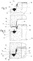
- the first exemplary embodiment in FIGS. 1 and 2 shows a component 10 for a push-in socket connection, which can be produced by pushing the component 10 together with a second part 11, the second part 11 and the component 10 being constructed identically.
- Both are, for example, a molded part, for example made of concrete or polymer concrete or fiber concrete or fiber cement or of clay or casting material or plastic or the like.
- the component 10 and / or the part 11 which is of the same construction for example, can be used as a street drain or yard drain or as a shaft ring or shaft neck or shaft base or as a chimney element or wall element or wall element or as a pipe or jacking pipe or gasoline separator or the like. be trained.
- the component 10 and likewise the second part 11, which is identical in terms of construction consists of a concrete part, for example for forming pipes, shafts or the like.
- At least one sealing device 12 which is then located within a sleeve gap 13, comes into contact with a lubricant 14 which is located on the contact surface 15 of the component 10.
- the component 10 has an upper tip end 16 with an approximately flat plane, e.g. annular, end face 17 and an adjacent, approximately cylindrical outer surface 18, which form the contact surface 15.
- the lubricant 14 can be located on the end face 17 and / or the outer surface 18. In the exemplary embodiment shown in FIGS. 1 and 2, the lubricant 14 is provided as a continuous layer both on the end face 17 and on the outer face 18.
- the component 10 in FIGS. 1 and 2 is provided at the lower end with a bell 19 which has the at least one sealing device 12.
- the second part 11 which is identical in construction to the component 10, has a lubricant 14 'at the upper tip end 16' and a bell 19 'at the lower end, in which the sealing device 12' is located.
- the lubricant 14, 14 ' is advantageously e.g. already adhered to the contact surface 15 or 15 'during the manufacture of the component 10 or 11.
- the component 10 or 11 produced in the concrete plant is then provided and delivered with lubricant 14, 14 'already applied during manufacture.
- the lubricant 14, 14 ' is preferably weather-resistant, in particular resistant to heat, solar radiation, cold, frost, moisture, rain, snow or the like.
- the respective component 10, 11 can be stored outdoors as usual or be exposed to all possible weather influences at the construction site without being disturbed.
- the lubricant 14, 14 ' is formed from a sliding layer which e.g. a wax layer or a resin-like or resin-like layer or instead a lacquer layer, preferably with a synthetic composition.
- the lubricant 14, 14 ' has a low coefficient of friction against rubber, synthetic rubber, an elastomer or the like.
- Elastic sealing material from which e.g. the sealing device 12, 12 'can consist entirely or partially.
- the lubricant 14, 14 ' in particular the wax layer or the resin-like or resin-like layer or the lacquer layer, can be applied in the liquid state. This can e.g. by spraying or spraying or brushing or immersing in an immersion bath or the like. Application by applying a film is also possible. It can be advantageous if the lubricant 14, 14 ', in particular in the form of a wax layer, is applied in a heated state. A lubricant in the form of a wax layer can advantageously be applied thinly in a hot process.
- the lubricant 14, 14 ' consists of a resin-like or resin-like layer, such materials likewise lead to such a creeping process when the components 10, 11 are pushed together. Such a resin-like or resin-like layer can also be applied in the heated state, such as a wax layer or also in cold condition.
- the lubricant 14, 14 ' consists of a Lacquer layer, preferably with a synthetic composition, such an applied lubricant 14, 14 'can harden on the contact surface 15, 15' of the component 10 or 11. With synthetic materials of this type there is the advantage that the properties can be optimally adjusted to the required requirements by means of different compositions, for example in particular with regard to sliding properties and weather resistance.
- the lubricant 14, 14 'can also consist of molybdenum disulfide and / or molybdenum sulfate and / or graphite.
- the at least one sealing device 12 of the component 10 or 12 'of the second, structurally identical component 11 is already incorporated with particular advantage into the material of the component 10 or 11 when the component 10 or 11 is shaped, in particular as a molded concrete part.
- the at least one sealing device 12 or 12 'already concreted in during the production of the component 10 or 11 has at least one compensating body 20, 20', the at least one inner cavity 21, 21 'with a filling 22, 22' made of non-compressible material contains. This filling 22 consists e.g.
- the filling 22 is able to act load-transferring and to effect load balancing.
- the at least one sealing device 12, 12 ' also has at least one compression sealing element 23, 23'.
- the lubricant 14 is applied to that area of the contact surface 15 on which the at least one sealing device 12 'slides along at the associated end, namely the bell 19', of the blue-identical second component 11 when the two components 10, 11 are pushed together.
- the at least one compression sealing element 23, 23 ' is pressed in the socket gap 13. Since the compression sealing element 23, 23 ', and at least this one, slides along the lubricant 14, 14', the friction factor between the sealing device 12, 12 'and the associated contact surface 15, 15' of the components 10, 11 is significantly reduced.
- the sealing device 12, 12 'thus slides easily on the associated sealing surface.
- the lubricant 14 is applied to that area of the contact surface 15 of the component 10 on which the compression sealing element 23 'and / or the compensating body 20' slides along at the associated end 19 'of the second component 11 when the two components 10, 11 are pushed together. Since the lubricant 14 is required above all for interaction with the compression sealing element 23 'pressed when the components 10, 11 are plugged together, it may be sufficient to apply the lubricant 14 only to that area of the contact surface 15, for example only in the area of the outer surface 18, where the compression sealing element 23 'of the second component 11 slides along when the two components 10, 11 are pushed together.
- the lubricant 14 in the component 10 is also attached to that area of the contact surface 15, that is to say not only on the outer surface 18 but also on the end face 17, on which the compensating body 20 'of the other component 11 is seated when the two are pushed together. Characterized in that the lubricant 14 is thus also applied to the end face 17, the load-balancing effect of the compensating body 20 'is improved because its filling 22' can thereby move more easily in the transverse direction on the tip end 16, in particular the end face 17.
- the component 110 in particular in the form of a concrete part, for example for the formation of pipes, shafts or the like, has a bell 119 at the lower end with an approximately flat, for example annular, end face 117 and an adjoining, approximately cylindrical one Inner surface 118 as contact surface 115.
- the lubricant 114 is provided on the end face 117 and / or the inner face 118 and is applied and designed in the same way as in the first exemplary embodiment.
- the lubricant 114 is provided as a continuous layer on the end face 117 and the inner face 118.
- Component 110 also has an upper tip end 116, which carries the at least one sealing device 112.
- the compression sealing element 123 is formed from an independent element separated from the compensating body 120.
- the compression sealing element 123 made of rubber, synthetic rubber, an elastomer or the like. is annular and applied to a shoulder 130 of the tip end 116.
- the separate compensating body 120 is approximately triangular in cross section, is ring-shaped and is inserted in a groove 131 of the component 110 which is recessed approximately V-shaped in cross section and in which the compensating body 120 is positively supported.
- the difference from the first exemplary embodiment in FIGS. 1 and 2 is thus that in the second exemplary embodiment in FIGS. 3 and 4 the at least one sealing device 112 is provided in the region of the tip end 116 of the component 110, while in the first exemplary embodiment the at least one sealing device 12 is arranged in the region of the lower bell 19. Accordingly, the lubricant 14 is provided in the second exemplary embodiment according to FIGS. 3 and 4 in the region of the bell 119, while in the first exemplary embodiment in FIGS. 1 and 2 the lubricant 14 is provided in the region of the tip end 16.
- the second component 111 of which only the upper tip end 116 'can be seen in FIG. 4, is constructed identically to the first component 110.
- the second component 111 at the tip end 116 ' also has a similar sealing device 112' with a compression sealing element 123 'and a compensating body 120', a lubricant similar to the lubricant 114 of the first component 110 also being provided at the lower end (not visible) in the region of the bell is.
- the load balancing is improved because a transverse displacement of the filling 122' in the compensating body 120 'on the end face 117 is thereby facilitated .
Landscapes
- Engineering & Computer Science (AREA)
- General Engineering & Computer Science (AREA)
- Mechanical Engineering (AREA)
- Gasket Seals (AREA)
- Sealing Material Composition (AREA)
Applications Claiming Priority (2)
| Application Number | Priority Date | Filing Date | Title |
|---|---|---|---|
| DE19522279 | 1995-06-20 | ||
| DE1995122279 DE19522279A1 (de) | 1995-06-20 | 1995-06-20 | Bauteil für Steckmuffenverbindung |
Publications (1)
| Publication Number | Publication Date |
|---|---|
| EP0750149A1 true EP0750149A1 (fr) | 1996-12-27 |
Family
ID=7764741
Family Applications (1)
| Application Number | Title | Priority Date | Filing Date |
|---|---|---|---|
| EP96109769A Withdrawn EP0750149A1 (fr) | 1995-06-20 | 1996-06-18 | Elément pour un raccord à manchon |
Country Status (2)
| Country | Link |
|---|---|
| EP (1) | EP0750149A1 (fr) |
| DE (1) | DE19522279A1 (fr) |
Cited By (3)
| Publication number | Priority date | Publication date | Assignee | Title |
|---|---|---|---|---|
| NL1006313C2 (nl) * | 1997-06-13 | 1998-12-15 | Wavin Bv | Buisverbinding. |
| EP1104825A3 (fr) * | 1999-11-11 | 2003-05-02 | Fellner-Feldegg, Robert | Elément de regard, en particulier anneau de regard en béton |
| EP2634468A1 (fr) * | 2012-02-29 | 2013-09-04 | DS Dichtungstechnik GmbH | Bague d'étanchéité et raccord de manchon emboîtable |
Families Citing this family (3)
| Publication number | Priority date | Publication date | Assignee | Title |
|---|---|---|---|---|
| DE19628639A1 (de) * | 1996-07-16 | 1998-01-29 | Cordes Theodor Gmbh & Co Kg | Dichtungsvorrichtung |
| DE19653952C2 (de) * | 1996-12-21 | 1999-02-25 | Cordes Theodor Gmbh & Co Kg | Rohrkörper mit zwei Elastomerringen und Gleithilfe |
| DE29809806U1 (de) | 1998-05-30 | 1998-08-20 | Züblin Schleuderbetonrohrwerke GmbH, 77694 Kehl | Betonrohr |
Citations (13)
| Publication number | Priority date | Publication date | Assignee | Title |
|---|---|---|---|---|
| DE2726331A1 (de) * | 1977-06-10 | 1978-12-14 | Thyssen Industrie | Bewegliche muffenverbindung fuer gussrohre |
| DE2900437A1 (de) * | 1978-01-11 | 1979-07-26 | Forsheda Gummifabrik Ab | Dichtring und verfahren zur herstellung desselben |
| EP0011919A1 (fr) * | 1978-10-27 | 1980-06-11 | A/S Den Norske Remfabrik | Joint en caoutchouc ou matériau similaire |
| US4414247A (en) * | 1981-03-30 | 1983-11-08 | Mannesmann Aktiengesellschaft | Method for surface treatment of threading |
| EP0343677A1 (fr) * | 1988-05-27 | 1989-11-29 | PT-Poly-Tec GmbH Vertrieb und Herstellung von Dichtungssystemen | Joint d'étanchéité entre deux éléments préfabriqués en béton, insérables l'un dans l'autre |
| DE3826622A1 (de) * | 1988-08-05 | 1990-02-08 | Continental Ag | Dichtung fuer muffenrohrverbindungen |
| DE3909381A1 (de) * | 1989-03-22 | 1990-12-06 | Cordes Theodor Gmbh & Co Kg | Dichtung |
| EP0471319A2 (fr) * | 1990-08-13 | 1992-02-19 | Forsheda-Stefa GmbH | Tuyau de béton |
| DE4112976A1 (de) * | 1991-04-20 | 1992-10-22 | Phoenix Ag | Steckmuffenverbindung |
| EP0556545A1 (fr) * | 1992-02-21 | 1993-08-25 | BODE GmbH | Bague d'étanchéité pour un dispositif de connexion à manchon |
| DE8601478U1 (de) * | 1986-01-22 | 1993-09-02 | Hermann Mücher GmbH & Co KG, 58332 Schwelm | Elastische Gleitdichtung |
| DE4229609A1 (de) * | 1992-09-04 | 1994-03-10 | Forsheda Stefa Gmbh | Abdichtung zwischen zwei ineinandersteckbaren Teilen |
| DE4323734A1 (de) * | 1993-07-15 | 1995-01-19 | Prinzing Georg Gmbh Co Kg | Dichtungseinrichtung an aneinanderstoßenden Bauteilen, insbesondere Betonformteilen |
-
1995
- 1995-06-20 DE DE1995122279 patent/DE19522279A1/de not_active Withdrawn
-
1996
- 1996-06-18 EP EP96109769A patent/EP0750149A1/fr not_active Withdrawn
Patent Citations (13)
| Publication number | Priority date | Publication date | Assignee | Title |
|---|---|---|---|---|
| DE2726331A1 (de) * | 1977-06-10 | 1978-12-14 | Thyssen Industrie | Bewegliche muffenverbindung fuer gussrohre |
| DE2900437A1 (de) * | 1978-01-11 | 1979-07-26 | Forsheda Gummifabrik Ab | Dichtring und verfahren zur herstellung desselben |
| EP0011919A1 (fr) * | 1978-10-27 | 1980-06-11 | A/S Den Norske Remfabrik | Joint en caoutchouc ou matériau similaire |
| US4414247A (en) * | 1981-03-30 | 1983-11-08 | Mannesmann Aktiengesellschaft | Method for surface treatment of threading |
| DE8601478U1 (de) * | 1986-01-22 | 1993-09-02 | Hermann Mücher GmbH & Co KG, 58332 Schwelm | Elastische Gleitdichtung |
| EP0343677A1 (fr) * | 1988-05-27 | 1989-11-29 | PT-Poly-Tec GmbH Vertrieb und Herstellung von Dichtungssystemen | Joint d'étanchéité entre deux éléments préfabriqués en béton, insérables l'un dans l'autre |
| DE3826622A1 (de) * | 1988-08-05 | 1990-02-08 | Continental Ag | Dichtung fuer muffenrohrverbindungen |
| DE3909381A1 (de) * | 1989-03-22 | 1990-12-06 | Cordes Theodor Gmbh & Co Kg | Dichtung |
| EP0471319A2 (fr) * | 1990-08-13 | 1992-02-19 | Forsheda-Stefa GmbH | Tuyau de béton |
| DE4112976A1 (de) * | 1991-04-20 | 1992-10-22 | Phoenix Ag | Steckmuffenverbindung |
| EP0556545A1 (fr) * | 1992-02-21 | 1993-08-25 | BODE GmbH | Bague d'étanchéité pour un dispositif de connexion à manchon |
| DE4229609A1 (de) * | 1992-09-04 | 1994-03-10 | Forsheda Stefa Gmbh | Abdichtung zwischen zwei ineinandersteckbaren Teilen |
| DE4323734A1 (de) * | 1993-07-15 | 1995-01-19 | Prinzing Georg Gmbh Co Kg | Dichtungseinrichtung an aneinanderstoßenden Bauteilen, insbesondere Betonformteilen |
Cited By (4)
| Publication number | Priority date | Publication date | Assignee | Title |
|---|---|---|---|---|
| NL1006313C2 (nl) * | 1997-06-13 | 1998-12-15 | Wavin Bv | Buisverbinding. |
| WO1998057089A1 (fr) * | 1997-06-13 | 1998-12-17 | Wavin B.V. | Raccord de tuyaux |
| EP1104825A3 (fr) * | 1999-11-11 | 2003-05-02 | Fellner-Feldegg, Robert | Elément de regard, en particulier anneau de regard en béton |
| EP2634468A1 (fr) * | 2012-02-29 | 2013-09-04 | DS Dichtungstechnik GmbH | Bague d'étanchéité et raccord de manchon emboîtable |
Also Published As
| Publication number | Publication date |
|---|---|
| DE19522279A1 (de) | 1997-01-02 |
Similar Documents
| Publication | Publication Date | Title |
|---|---|---|
| EP0485706B1 (fr) | Réseau d'alimentation en eau sanitaire ou de chauffage constitué complètement ou principalement de matière plastique, plus specialement en polypropylène | |
| DE102008039446A1 (de) | Kraftübertragungselement, Gleithülse, Anordnung sowie Verfahren zur Herstellung einer unlösbaren Werkstückverbindung | |
| DE3414180A1 (de) | Dichtungseinrichtung fuer aneinanderstossende, zumindest etwa rohrfoermige bauteile, insbesondere fuer betonformteile | |
| DE4108851A1 (de) | Steckmuffenverbindung | |
| EP0634532B1 (fr) | Arrangement pour joint d'étanchéité pour élément de construction | |
| EP0426147B1 (fr) | Tuyau en béton ayant un revêtement interne anticorrosif à raccords de tuyau adaptés et dispositifs d'étanchéité intégrés dans les zones de raccordement | |
| DD292510A5 (de) | Dichtring | |
| DE19522279A1 (de) | Bauteil für Steckmuffenverbindung | |
| DE29709874U1 (de) | Kamin-Rauchrohr aus Muffenrohr-Abschnitten und deren Abdichtung | |
| DE102007011607A1 (de) | Rohrverbindung | |
| EP0348870B1 (fr) | Construction constituée par l'assemblage d'éléments préfabriqués en béton armé utilisant la technique du béton précontraint | |
| EP0899387A1 (fr) | Procédé de rénovation de la base des puits de regard | |
| CH679786A5 (fr) | ||
| EP0343677A1 (fr) | Joint d'étanchéité entre deux éléments préfabriqués en béton, insérables l'un dans l'autre | |
| DE4124628A1 (de) | Injektionsschlauch fuer fugen an bauwerken | |
| EP0705999A1 (fr) | Dispositif pour l'étanchéité d'un joint dans une construction | |
| DE4420807A1 (de) | Höhenverstellbares Stützelement | |
| EP4151896B1 (fr) | Raccord de tuyaux | |
| EP0611276A1 (fr) | Pièce de connexion pour raccorder une armature métallique à un tuyau en plastique transportant des produits liquides | |
| DE2441118A1 (de) | Abdichtung an profilbauteilen | |
| DE9217222U1 (de) | Abdichtung an zusammensteckbaren Betonfertigteilen | |
| EP0347608B1 (fr) | Joint d'étanchéité | |
| DE2654059A1 (de) | Lippendichtungsring | |
| EP1344970B1 (fr) | Elément d'étanchéité annulaire | |
| DE4443983C2 (de) | Schachtanordnung |
Legal Events
| Date | Code | Title | Description |
|---|---|---|---|
| PUAI | Public reference made under article 153(3) epc to a published international application that has entered the european phase |
Free format text: ORIGINAL CODE: 0009012 |
|
| AK | Designated contracting states |
Kind code of ref document: A1 Designated state(s): AT DE FR |
|
| 17P | Request for examination filed |
Effective date: 19970415 |
|
| 17Q | First examination report despatched |
Effective date: 19990519 |
|
| STAA | Information on the status of an ep patent application or granted ep patent |
Free format text: STATUS: THE APPLICATION IS DEEMED TO BE WITHDRAWN |
|
| 18D | Application deemed to be withdrawn |
Effective date: 19990930 |