EP0750940B1 - Garnissage organisé - Google Patents
Garnissage organisé Download PDFInfo
- Publication number
- EP0750940B1 EP0750940B1 EP96304590A EP96304590A EP0750940B1 EP 0750940 B1 EP0750940 B1 EP 0750940B1 EP 96304590 A EP96304590 A EP 96304590A EP 96304590 A EP96304590 A EP 96304590A EP 0750940 B1 EP0750940 B1 EP 0750940B1
- Authority
- EP
- European Patent Office
- Prior art keywords
- vapour
- liquid
- projections
- sheets
- contact column
- Prior art date
- Legal status (The legal status is an assumption and is not a legal conclusion. Google has not performed a legal analysis and makes no representation as to the accuracy of the status listed.)
- Expired - Lifetime
Links
- 238000012856 packing Methods 0.000 title claims description 35
- 239000012071 phase Substances 0.000 claims description 23
- 239000007791 liquid phase Substances 0.000 claims description 12
- 230000001174 ascending effect Effects 0.000 claims description 2
- 239000002184 metal Substances 0.000 claims 1
- 238000012546 transfer Methods 0.000 description 9
- 239000007788 liquid Substances 0.000 description 8
- 238000013461 design Methods 0.000 description 3
- 239000010408 film Substances 0.000 description 3
- 239000000463 material Substances 0.000 description 3
- 230000015572 biosynthetic process Effects 0.000 description 2
- 238000001311 chemical methods and process Methods 0.000 description 1
- 238000004821 distillation Methods 0.000 description 1
- 239000011552 falling film Substances 0.000 description 1
- 239000012634 fragment Substances 0.000 description 1
- 230000002401 inhibitory effect Effects 0.000 description 1
- 238000004519 manufacturing process Methods 0.000 description 1
- 238000000034 method Methods 0.000 description 1
- 238000012986 modification Methods 0.000 description 1
- 230000004048 modification Effects 0.000 description 1
- 238000001179 sorption measurement Methods 0.000 description 1
Images

Classifications
-
- F—MECHANICAL ENGINEERING; LIGHTING; HEATING; WEAPONS; BLASTING
- F28—HEAT EXCHANGE IN GENERAL
- F28F—DETAILS OF HEAT-EXCHANGE AND HEAT-TRANSFER APPARATUS, OF GENERAL APPLICATION
- F28F25/00—Component parts of trickle coolers
- F28F25/02—Component parts of trickle coolers for distributing, circulating, and accumulating liquid
- F28F25/08—Splashing boards or grids, e.g. for converting liquid sprays into liquid films; Elements or beds for increasing the area of the contact surface
- F28F25/087—Vertical or inclined sheets; Supports or spacers
-
- B—PERFORMING OPERATIONS; TRANSPORTING
- B01—PHYSICAL OR CHEMICAL PROCESSES OR APPARATUS IN GENERAL
- B01J—CHEMICAL OR PHYSICAL PROCESSES, e.g. CATALYSIS OR COLLOID CHEMISTRY; THEIR RELEVANT APPARATUS
- B01J19/00—Chemical, physical or physico-chemical processes in general; Their relevant apparatus
- B01J19/32—Packing elements in the form of grids or built-up elements for forming a unit or module inside the apparatus for mass or heat transfer
-
- B—PERFORMING OPERATIONS; TRANSPORTING
- B01—PHYSICAL OR CHEMICAL PROCESSES OR APPARATUS IN GENERAL
- B01J—CHEMICAL OR PHYSICAL PROCESSES, e.g. CATALYSIS OR COLLOID CHEMISTRY; THEIR RELEVANT APPARATUS
- B01J2219/00—Chemical, physical or physico-chemical processes in general; Their relevant apparatus
- B01J2219/32—Details relating to packing elements in the form of grids or built-up elements for forming a unit of module inside the apparatus for mass or heat transfer
- B01J2219/322—Basic shape of the elements
- B01J2219/32203—Sheets
- B01J2219/3221—Corrugated sheets
-
- B—PERFORMING OPERATIONS; TRANSPORTING
- B01—PHYSICAL OR CHEMICAL PROCESSES OR APPARATUS IN GENERAL
- B01J—CHEMICAL OR PHYSICAL PROCESSES, e.g. CATALYSIS OR COLLOID CHEMISTRY; THEIR RELEVANT APPARATUS
- B01J2219/00—Chemical, physical or physico-chemical processes in general; Their relevant apparatus
- B01J2219/32—Details relating to packing elements in the form of grids or built-up elements for forming a unit of module inside the apparatus for mass or heat transfer
- B01J2219/322—Basic shape of the elements
- B01J2219/32203—Sheets
- B01J2219/32213—Plurality of essentially parallel sheets
-
- B—PERFORMING OPERATIONS; TRANSPORTING
- B01—PHYSICAL OR CHEMICAL PROCESSES OR APPARATUS IN GENERAL
- B01J—CHEMICAL OR PHYSICAL PROCESSES, e.g. CATALYSIS OR COLLOID CHEMISTRY; THEIR RELEVANT APPARATUS
- B01J2219/00—Chemical, physical or physico-chemical processes in general; Their relevant apparatus
- B01J2219/32—Details relating to packing elements in the form of grids or built-up elements for forming a unit of module inside the apparatus for mass or heat transfer
- B01J2219/322—Basic shape of the elements
- B01J2219/32203—Sheets
- B01J2219/32237—Sheets comprising apertures or perforations
- B01J2219/32241—Louvres
-
- B—PERFORMING OPERATIONS; TRANSPORTING
- B01—PHYSICAL OR CHEMICAL PROCESSES OR APPARATUS IN GENERAL
- B01J—CHEMICAL OR PHYSICAL PROCESSES, e.g. CATALYSIS OR COLLOID CHEMISTRY; THEIR RELEVANT APPARATUS
- B01J2219/00—Chemical, physical or physico-chemical processes in general; Their relevant apparatus
- B01J2219/32—Details relating to packing elements in the form of grids or built-up elements for forming a unit of module inside the apparatus for mass or heat transfer
- B01J2219/322—Basic shape of the elements
- B01J2219/32203—Sheets
- B01J2219/32248—Sheets comprising areas that are raised or sunken from the plane of the sheet
- B01J2219/32251—Dimples, bossages, protrusions
-
- B—PERFORMING OPERATIONS; TRANSPORTING
- B01—PHYSICAL OR CHEMICAL PROCESSES OR APPARATUS IN GENERAL
- B01J—CHEMICAL OR PHYSICAL PROCESSES, e.g. CATALYSIS OR COLLOID CHEMISTRY; THEIR RELEVANT APPARATUS
- B01J2219/00—Chemical, physical or physico-chemical processes in general; Their relevant apparatus
- B01J2219/32—Details relating to packing elements in the form of grids or built-up elements for forming a unit of module inside the apparatus for mass or heat transfer
- B01J2219/324—Composition or microstructure of the elements
- B01J2219/32408—Metal
-
- Y—GENERAL TAGGING OF NEW TECHNOLOGICAL DEVELOPMENTS; GENERAL TAGGING OF CROSS-SECTIONAL TECHNOLOGIES SPANNING OVER SEVERAL SECTIONS OF THE IPC; TECHNICAL SUBJECTS COVERED BY FORMER USPC CROSS-REFERENCE ART COLLECTIONS [XRACs] AND DIGESTS
- Y10—TECHNICAL SUBJECTS COVERED BY FORMER USPC
- Y10T—TECHNICAL SUBJECTS COVERED BY FORMER US CLASSIFICATION
- Y10T428/00—Stock material or miscellaneous articles
- Y10T428/24—Structurally defined web or sheet [e.g., overall dimension, etc.]
- Y10T428/24479—Structurally defined web or sheet [e.g., overall dimension, etc.] including variation in thickness
- Y10T428/2457—Parallel ribs and/or grooves
-
- Y—GENERAL TAGGING OF NEW TECHNOLOGICAL DEVELOPMENTS; GENERAL TAGGING OF CROSS-SECTIONAL TECHNOLOGIES SPANNING OVER SEVERAL SECTIONS OF THE IPC; TECHNICAL SUBJECTS COVERED BY FORMER USPC CROSS-REFERENCE ART COLLECTIONS [XRACs] AND DIGESTS
- Y10—TECHNICAL SUBJECTS COVERED BY FORMER USPC
- Y10T—TECHNICAL SUBJECTS COVERED BY FORMER US CLASSIFICATION
- Y10T428/00—Stock material or miscellaneous articles
- Y10T428/24—Structurally defined web or sheet [e.g., overall dimension, etc.]
- Y10T428/24628—Nonplanar uniform thickness material
- Y10T428/24669—Aligned or parallel nonplanarities
- Y10T428/24694—Parallel corrugations
- Y10T428/24711—Plural corrugated components
-
- Y—GENERAL TAGGING OF NEW TECHNOLOGICAL DEVELOPMENTS; GENERAL TAGGING OF CROSS-SECTIONAL TECHNOLOGIES SPANNING OVER SEVERAL SECTIONS OF THE IPC; TECHNICAL SUBJECTS COVERED BY FORMER USPC CROSS-REFERENCE ART COLLECTIONS [XRACs] AND DIGESTS
- Y10—TECHNICAL SUBJECTS COVERED BY FORMER USPC
- Y10T—TECHNICAL SUBJECTS COVERED BY FORMER US CLASSIFICATION
- Y10T428/00—Stock material or miscellaneous articles
- Y10T428/24—Structurally defined web or sheet [e.g., overall dimension, etc.]
- Y10T428/24744—Longitudinal or transverse tubular cavity or cell
Definitions
- the present invention relates to a liquid-vapour contact column containing a structured packing for producing intimate contact between vapour and liquid phases. More particularly, the present invention relates to such a liquid-vapour contact column containing a structured packing formed of a plurality of juxtaposed sheets having corrugations to define fine flow channels.
- Structured packing In many chemical process applications, for instance heat exchange, adsorption, distillation, it is necessary to bring liquid and vapour phases into contact with one another. Such contact is induced by various liquid-vapour contact media such as sieve plates, trays and structured packing. Structured packing has found increased use in process applications due to its predictable performance and its low pressure drop characteristics. Structured packing consists of a plurality of juxtaposed sheets having corrugations and can be obtained with various packing densities, angular relationships between the corrugations, and performance characteristics.
- the invention therefore aims at providing a liquid-vapour contact column containing a structured packing which has improved heat and mass transfer characteristics:
- a liquid-vapour contact column containing a structured packing for producing intimate contact between ascending vapour and descending liquid phases, said structured packing comprising:
- the present invention by producing turbulence tends to produce greater mass transfer between the vapour phase and the liquid phase by inhibiting the formation of a stable concentration gradient in which some of the vapour passing through the flow channels tends not to interact with the liquid film on the surface of the packing.
- This will increase the performance of the packing with respect to the rate of mass transfer between the liquid and vapour phases.
- the production of turbulence could potentially lead to a large increase in the pressure drop in the packing and thus degrade the performance of the packing.
- the spacing of the projections is carefully selected so as to produce a subsidence of turbulence between adjacent projections.
- FIG. 1 illustrates just three adjacent sheets 10, 20 and 30 of structured packing which are in juxtaposition. Corrugations within sheet 10 define flow channels 12, 14, 16 and 18 which are set opposite to flow channels 22, 24, 26 and 28 in sheet 20.
- the corrugations in sheet 30 provide flow channels 32, 36, 38, 40 and 42 which are set opposite to flow channels 44, 46, 48, 50, and 52 in sheet 20.
- the second sheet 20 is orientated with its corrugations at an angle to those of sheets 10 and 30 so that the respective flow channels criss-cross. This criss-crossing of flow channels increases the mixing between the vapour and liquid phases.
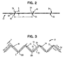
- projections 54 are provided on one side of the sheet 10 and projections 55 on the other side to produce turbulence in the vapour phase as it ascends the structured packing.
- Projections 54,55 each comprise a cut out tab bent away from sheet 10.
- Projections 54, 55 have inwardly sloping side edges, such as 56 and 58 to allow liquid film to flow between projections 54, 55.
- the tabs may be provided on only one side of each flow.
- projections may be provided on only one side of each of the sheets.
- such an embodiment of the present invention is possible which is only provided with projections 54 and not projections bent in an opposite direction such as projections 55.
- the advantage of such alternative embodiments is to decrease interference between the projections 54,55 and the descending liquid phase.
- the flow channels 12-18, 22-28, 32-42, and 44-52 each have a channel dimension S.
- the height of projections 54,55 designated by reference h, is preferably in a range of between about 5% and about 20% of the dimension S of the channel side.
- the projection spacing dimension, "p" is preferably in a range of between about 2 and about 12 times the height of the projections, h.
- Flow channels exist on both sides of each of corrugated sheets 10, 20 and 30, so that (as viewed in the illustration) projections 54 project upwardly from the surface while projections 55 project downwardly from the surface. Openings 60 are thus formed which allow liquid to flow between the flow channels.
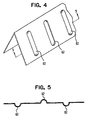
- the projections of this embodiment comprise rib-like embossments 62 which alternate so as to project from both surfaces of the packing sheet.
- projections similar to those of projections 54,55 but formed of tabs bent at less than right angles to the sheets are orientated in a direction parallel to the transverse dimension of the sheets, the projections could be orientated at an angle to such transverse dimension.
- projections illustrated herein are shown as single tabs or ribs which extend more or less across one entire wall or surface of a flow channel, groups of small tabs or ribs with intervening spaces could be used to form the turbulence producing projections. These small tabs or ribs could be angled with respect to one another, for instance in a V-like configuration, to produce a greater or lesser degree of turbulence to optimise the packing design for a particular application. In this regard, when turbulence is said to subside between projections it is to be understood that the turbulence subsides in the intervening spaces between such groups of tabs or ribs.
Landscapes
- Physics & Mathematics (AREA)
- Thermal Sciences (AREA)
- Engineering & Computer Science (AREA)
- Chemical & Material Sciences (AREA)
- Mechanical Engineering (AREA)
- General Engineering & Computer Science (AREA)
- Organic Chemistry (AREA)
- Chemical Kinetics & Catalysis (AREA)
- Vaporization, Distillation, Condensation, Sublimation, And Cold Traps (AREA)
- Physical Or Chemical Processes And Apparatus (AREA)
- Heat-Exchange Devices With Radiators And Conduit Assemblies (AREA)
Claims (8)
- Colonne de contact liquide-vapeur contenant un garnissage structuré destiné à produire un contact étroit entre une phase vapeur ascendante et une phase liquide descendante, ledit garnissage structuré comprenant :caractérisée en ce queune pluralité de feuilles juxtaposées (10, 20, 30) sur chacune desquelles ladite phase liquide descend sous forme d'un film ;lesdites feuilles présentant des plissements définissant des rigoles d'écoulement (12, 14, 16, 18, 22, 24, 26, 28, 32, 36, 38, 40, 42, 44, 46, 48, 50 et 52) pour que ladite phase vapeur monte dans le garnissage structuré et entre en contact avec ladite phase liquide, dans laquellelesdites feuilles ont une pluralité de saillies (54, 55, 62) situées sur au moins un côté de chaque rigole d'écoulement sur au moins un côté de chacune desdites feuilles, configurées et orientées de manière à produire, à l'utilisation, un mélange turbulent dans ladite phase vapeur et ainsi à empêcher les gradients de concentrations de survenir dans la phase vapeur dans des directions normales aux surfaces desdits plissements définissant lesdites rigoles d'écoulement,
lesdites saillies (54, 55, 62) sont disposées à intervalles espacés le long de chaque rigole d'écoulement afin que, à l'utilisation, ladite turbulence dans ladite phase vapeur s'apaise entre chaque paire d'intervalles adjacents dans la direction de l'écoulement de la vapeur, et lesdites saillies (54, 55) ont chacune une hauteur (h) dans une plage comprise entre 5 % et 20 % de la (des) mesure(s) d'un (des) côté(s) d'une rigole d'écoulement, et l'écartement (p) entre chaque paire d'intervalles adjacents est dans une plage comprise entre 2 et 12 fois ladite hauteur (h). - Colonne de contact liquide-vapeur selon la Revendication 1, dans laquelle à chaque intervalle se trouve une seule saillie longitudinale (54, 55, 62) ou un groupe de saillies.
- Colonne de contact liquide-vapeur selon la Revendication 1 ou la Revendication 2, dans laquelle lesdites feuilles (10, 20, 30) sont fabriquées en tôle.
- Colonne de contact liquide-vapeur selon l'une quelconque des Revendications précédentes, dans laquelle les plissements de chaque feuille sont en angle par rapport à ceux des feuilles adjacentes en vis-à-vis.
- Colonne de contact liquide-vapeur selon l'une quelconque des Revendications précédentes, dans laquelle chaque saillie comporte un onglet découpé éloigné par pliage de sa feuille.
- Colonne de contact liquide-vapeur selon la Revendication 5, dans laquelle lesdits onglets découpés ont des bords latéraux s'inclinant vers l'intérieur.
- Colonne de contact liquide-vapeur selon l'une quelconque des Revendications 1 à 4, dans laquelle lesdites saillies (62) comprennent des bossages en forme de nervures.
- Colonne de contact liquide-vapeur selon l'une quelconque des Revendications précédentes, dans laquelle lesdites saillies (54, 55, 62) sont orientées transversalement aux axes longitudinaux desdits plissements.
Applications Claiming Priority (2)
| Application Number | Priority Date | Filing Date | Title |
|---|---|---|---|
| US495159 | 1983-05-17 | ||
| US08/495,159 US5624733A (en) | 1995-06-27 | 1995-06-27 | Structured packing |
Publications (2)
| Publication Number | Publication Date |
|---|---|
| EP0750940A1 EP0750940A1 (fr) | 1997-01-02 |
| EP0750940B1 true EP0750940B1 (fr) | 2001-12-12 |
Family
ID=23967498
Family Applications (1)
| Application Number | Title | Priority Date | Filing Date |
|---|---|---|---|
| EP96304590A Expired - Lifetime EP0750940B1 (fr) | 1995-06-27 | 1996-06-20 | Garnissage organisé |
Country Status (6)
| Country | Link |
|---|---|
| US (1) | US5624733A (fr) |
| EP (1) | EP0750940B1 (fr) |
| JP (1) | JPH0961069A (fr) |
| AU (1) | AU710140B2 (fr) |
| DE (1) | DE69617811T2 (fr) |
| ZA (1) | ZA964058B (fr) |
Families Citing this family (15)
| Publication number | Priority date | Publication date | Assignee | Title |
|---|---|---|---|---|
| US6277340B1 (en) | 1998-01-02 | 2001-08-21 | Abb Lummus Global, Inc. | Structured packing and element therefor |
| US6325360B1 (en) | 1998-12-23 | 2001-12-04 | Alberta Research Council Inc. | Structured packing assembly |
| CA2257128A1 (fr) * | 1998-12-23 | 2000-06-23 | Alberta Research Council | Empilage structure |
| CN1274401C (zh) * | 2001-07-06 | 2006-09-13 | 液体空气乔治洛德方法利用和研究的具有监督和管理委员会的有限公司 | 用于填充模块的带、相应的模块和设备 |
| RU2225753C2 (ru) * | 2002-04-22 | 2004-03-20 | Открытое акционерное общество "Научно-исследовательский и проектный институт по переработке газа" | Насадка для массообменных аппаратов |
| US6874769B2 (en) | 2002-10-03 | 2005-04-05 | Koch-Glitsch, Lp | Structured packing plate and element and method of fabricating same |
| RU2226125C1 (ru) * | 2003-02-28 | 2004-03-27 | Закрытое акционерное общество "Каустик" | Контактное устройство для массообменных аппаратов |
| US7237769B2 (en) * | 2004-06-30 | 2007-07-03 | Spx Cooling Technologies, Inc. | Cooling tower film fill apparatus and method |
| FR2919072B1 (fr) * | 2007-07-20 | 2009-09-11 | Schneider Electric Ind Sas | Detecteur de proximite inductif a bobinages commutes. |
| US8298412B2 (en) * | 2008-09-17 | 2012-10-30 | Koch-Glitsch, Lp | Structured packing module for mass transfer column and process involving same |
| FR2939339B1 (fr) * | 2008-12-04 | 2011-03-18 | Air Liquide | Procede et dispositif de fabrication d'une onde de garnissage structure, et appareil de traitement de fluides correspondant |
| JP6641844B2 (ja) * | 2015-09-30 | 2020-02-05 | 株式会社Ihi | 充填材 |
| EP3225304A1 (fr) | 2016-03-31 | 2017-10-04 | Hirschberg Engineering | Contacteur |
| US10953382B2 (en) * | 2017-06-09 | 2021-03-23 | Koch-Glitsch, Lp | Structured packing module for mass transfer columns |
| CN117776343B (zh) * | 2024-01-09 | 2025-10-03 | 徐州市市政设计院有限公司 | 一种微电解中空铁碳填料管及其制备方法与应用 |
Family Cites Families (11)
| Publication number | Priority date | Publication date | Assignee | Title |
|---|---|---|---|---|
| CH583584A5 (fr) * | 1972-10-18 | 1977-01-14 | Regehr Ulrich | |
| GB8304683D0 (en) * | 1983-02-19 | 1983-03-23 | Wigley A F | Moisture eliminator |
| US4604247A (en) * | 1983-06-21 | 1986-08-05 | Glitsch, Inc. | Tower packing material and method |
| DE3414267A1 (de) * | 1984-04-14 | 1985-11-07 | Raschig Gmbh, 6700 Ludwigshafen | Einbauelement fuer stoff- oder waermeaustauschkolonnen |
| IT8423267U1 (it) * | 1984-09-21 | 1986-03-21 | Bs Smogless S P A | Riempimento plastico modulare per il trattamento biologico delle acque reflue mediante percolazione. |
| HU195314B (en) * | 1985-07-23 | 1988-04-28 | Villamos Ipari Kutato Intezet | Cooling insert for equipments carrying out heat and material exchange being between gaseous medium and fluid particularly for cooling towers and degasing units |
| US4676934A (en) * | 1985-09-27 | 1987-06-30 | Jaeger Products, Inc. | Structured WV packing elements |
| US4668443A (en) * | 1985-11-25 | 1987-05-26 | Brentwood Industries, Inc. | Contact bodies |
| US5057250A (en) * | 1990-11-27 | 1991-10-15 | Glitsch, Inc. | Tower packing with small louvers |
| US5188773A (en) * | 1990-11-27 | 1993-02-23 | Glitsch, Inc. | Tower packing with small and large louvers and mixing method |
| US5185106A (en) * | 1990-11-27 | 1993-02-09 | Glitsch, Inc. | Tower packing with small louvers and mixing method |
-
1995
- 1995-06-27 US US08/495,159 patent/US5624733A/en not_active Expired - Fee Related
-
1996
- 1996-05-21 ZA ZA964058A patent/ZA964058B/xx unknown
- 1996-05-27 AU AU54539/96A patent/AU710140B2/en not_active Ceased
- 1996-06-06 JP JP8143840A patent/JPH0961069A/ja not_active Withdrawn
- 1996-06-20 DE DE69617811T patent/DE69617811T2/de not_active Expired - Fee Related
- 1996-06-20 EP EP96304590A patent/EP0750940B1/fr not_active Expired - Lifetime
Also Published As
| Publication number | Publication date |
|---|---|
| ZA964058B (en) | 1996-12-03 |
| AU710140B2 (en) | 1999-09-16 |
| DE69617811T2 (de) | 2002-08-29 |
| US5624733A (en) | 1997-04-29 |
| EP0750940A1 (fr) | 1997-01-02 |
| DE69617811D1 (de) | 2002-01-24 |
| JPH0961069A (ja) | 1997-03-07 |
| AU5453996A (en) | 1997-01-09 |
Similar Documents
| Publication | Publication Date | Title |
|---|---|---|
| EP0750940A1 (fr) | Garnissage organisé | |
| JP2530119B2 (ja) | 蒸溜塔などのパツキング | |
| EP0454179B1 (fr) | Eléments de remplissage pour une tour de refroidissement | |
| US6206349B1 (en) | Fluid-fluid contacting apparatus | |
| US4497751A (en) | Zig-zag profile packing and method of making | |
| EP0671963B1 (fr) | Garnissage a emboitement pour colonne echangeuse | |
| EP0707885B1 (fr) | Garnissage organisé à capacité accrue pour systèmes de rectification | |
| US4107241A (en) | Contacting arrangement for mass transfer operations | |
| US5876638A (en) | Structured packing element with bi-directional surface texture and a mass and heat transfer process using such packing element | |
| EP1210977A1 (fr) | Garnissage pour de colonne d'échange de chaleur | |
| US20010038811A1 (en) | Structured packing and element therefor | |
| US4304738A (en) | Packing Material and apparatus | |
| EP1036590A2 (fr) | Garnissage structuré à ondulations | |
| US6119481A (en) | Horizontal structured packing | |
| US3013781A (en) | Fractionating apparatus | |
| US7025339B2 (en) | Structured packing with increased capacity | |
| EP0748644B1 (fr) | Dispositif de contact de liquide/vapeur | |
| US5975503A (en) | Structured packing assembly | |
| EP0492802B1 (fr) | Garniture de tour pourvues de grilles | |
| US6991222B2 (en) | Structured packing with increased capacity | |
| US3687818A (en) | Distillation apparatus | |
| US5730000A (en) | Structured packing element and a mass and heat transfer process using such packing element | |
| US5525271A (en) | Liquid-vapor contact device | |
| KR100398813B1 (ko) | 증류장치용 타워인터널의 구조 패킹 | |
| US6325360B1 (en) | Structured packing assembly |
Legal Events
| Date | Code | Title | Description |
|---|---|---|---|
| PUAI | Public reference made under article 153(3) epc to a published international application that has entered the european phase |
Free format text: ORIGINAL CODE: 0009012 |
|
| AK | Designated contracting states |
Kind code of ref document: A1 Designated state(s): DE FR GB IT |
|
| 17P | Request for examination filed |
Effective date: 19970107 |
|
| 17Q | First examination report despatched |
Effective date: 19990315 |
|
| GRAG | Despatch of communication of intention to grant |
Free format text: ORIGINAL CODE: EPIDOS AGRA |
|
| GRAG | Despatch of communication of intention to grant |
Free format text: ORIGINAL CODE: EPIDOS AGRA |
|
| GRAH | Despatch of communication of intention to grant a patent |
Free format text: ORIGINAL CODE: EPIDOS IGRA |
|
| GRAH | Despatch of communication of intention to grant a patent |
Free format text: ORIGINAL CODE: EPIDOS IGRA |
|
| GRAA | (expected) grant |
Free format text: ORIGINAL CODE: 0009210 |
|
| AK | Designated contracting states |
Kind code of ref document: B1 Designated state(s): DE FR GB IT |
|
| PG25 | Lapsed in a contracting state [announced via postgrant information from national office to epo] |
Ref country code: IT Free format text: LAPSE BECAUSE OF FAILURE TO SUBMIT A TRANSLATION OF THE DESCRIPTION OR TO PAY THE FEE WITHIN THE PRE;WARNING: LAPSES OF ITALIAN PATENTS WITH EFFECTIVE DATE BEFORE 2007 MAY HAVE OCCURRED AT ANY TIME BEFORE 2007. THE CORRECT EFFECTIVE DATE MAY BE DIFFERENT FROM THE ONE RECORDED.SCRIBED TIME-LIMIT Effective date: 20011212 |
|
| REG | Reference to a national code |
Ref country code: GB Ref legal event code: IF02 |
|
| REF | Corresponds to: |
Ref document number: 69617811 Country of ref document: DE Date of ref document: 20020124 |
|
| ET | Fr: translation filed | ||
| PGFP | Annual fee paid to national office [announced via postgrant information from national office to epo] |
Ref country code: FR Payment date: 20020530 Year of fee payment: 7 |
|
| PGFP | Annual fee paid to national office [announced via postgrant information from national office to epo] |
Ref country code: GB Payment date: 20020612 Year of fee payment: 7 |
|
| PGFP | Annual fee paid to national office [announced via postgrant information from national office to epo] |
Ref country code: DE Payment date: 20020620 Year of fee payment: 7 |
|
| PLBE | No opposition filed within time limit |
Free format text: ORIGINAL CODE: 0009261 |
|
| STAA | Information on the status of an ep patent application or granted ep patent |
Free format text: STATUS: NO OPPOSITION FILED WITHIN TIME LIMIT |
|
| 26N | No opposition filed | ||
| PG25 | Lapsed in a contracting state [announced via postgrant information from national office to epo] |
Ref country code: GB Free format text: LAPSE BECAUSE OF NON-PAYMENT OF DUE FEES Effective date: 20030620 |
|
| PG25 | Lapsed in a contracting state [announced via postgrant information from national office to epo] |
Ref country code: DE Free format text: LAPSE BECAUSE OF NON-PAYMENT OF DUE FEES Effective date: 20040101 |
|
| GBPC | Gb: european patent ceased through non-payment of renewal fee |
Effective date: 20030620 |
|
| PG25 | Lapsed in a contracting state [announced via postgrant information from national office to epo] |
Ref country code: FR Free format text: LAPSE BECAUSE OF NON-PAYMENT OF DUE FEES Effective date: 20040227 |
|
| REG | Reference to a national code |
Ref country code: FR Ref legal event code: ST |