EP0751016B1 - Vorrichtung zur Abdichtung eines Gaskanals - Google Patents
Vorrichtung zur Abdichtung eines Gaskanals Download PDFInfo
- Publication number
- EP0751016B1 EP0751016B1 EP96105322A EP96105322A EP0751016B1 EP 0751016 B1 EP0751016 B1 EP 0751016B1 EP 96105322 A EP96105322 A EP 96105322A EP 96105322 A EP96105322 A EP 96105322A EP 0751016 B1 EP0751016 B1 EP 0751016B1
- Authority
- EP
- European Patent Office
- Prior art keywords
- rings
- gas
- slip rings
- sealing
- gas conduit
- Prior art date
- Legal status (The legal status is an assumption and is not a legal conclusion. Google has not performed a legal analysis and makes no representation as to the accuracy of the status listed.)
- Expired - Lifetime
Links
- 238000007789 sealing Methods 0.000 title claims description 14
- 230000002093 peripheral effect Effects 0.000 claims description 4
- 238000005096 rolling process Methods 0.000 claims description 4
- 230000000694 effects Effects 0.000 claims description 3
- 239000000314 lubricant Substances 0.000 claims description 2
- 239000003921 oil Substances 0.000 description 3
- 238000009434 installation Methods 0.000 description 2
- 239000010687 lubricating oil Substances 0.000 description 2
Images
Classifications
-
- B—PERFORMING OPERATIONS; TRANSPORTING
- B60—VEHICLES IN GENERAL
- B60C—VEHICLE TYRES; TYRE INFLATION; TYRE CHANGING; CONNECTING VALVES TO INFLATABLE ELASTIC BODIES IN GENERAL; DEVICES OR ARRANGEMENTS RELATED TO TYRES
- B60C23/00—Devices for measuring, signalling, controlling, or distributing tyre pressure or temperature, specially adapted for mounting on vehicles; Arrangement of tyre inflating devices on vehicles, e.g. of pumps or of tanks; Tyre cooling arrangements
- B60C23/001—Devices for manually or automatically controlling or distributing tyre pressure whilst the vehicle is moving
- B60C23/003—Devices for manually or automatically controlling or distributing tyre pressure whilst the vehicle is moving comprising rotational joints between vehicle-mounted pressure sources and the tyres
- B60C23/00363—Details of sealings
-
- B—PERFORMING OPERATIONS; TRANSPORTING
- B60—VEHICLES IN GENERAL
- B60C—VEHICLE TYRES; TYRE INFLATION; TYRE CHANGING; CONNECTING VALVES TO INFLATABLE ELASTIC BODIES IN GENERAL; DEVICES OR ARRANGEMENTS RELATED TO TYRES
- B60C23/00—Devices for measuring, signalling, controlling, or distributing tyre pressure or temperature, specially adapted for mounting on vehicles; Arrangement of tyre inflating devices on vehicles, e.g. of pumps or of tanks; Tyre cooling arrangements
- B60C23/001—Devices for manually or automatically controlling or distributing tyre pressure whilst the vehicle is moving
- B60C23/003—Devices for manually or automatically controlling or distributing tyre pressure whilst the vehicle is moving comprising rotational joints between vehicle-mounted pressure sources and the tyres
- B60C23/00381—Devices for manually or automatically controlling or distributing tyre pressure whilst the vehicle is moving comprising rotational joints between vehicle-mounted pressure sources and the tyres specially adapted for steerable wheels
Definitions
- the invention relates to a device for sealing a gas channel between two machine parts rotating relative to each other in a tire pressure adjusting device of motor vehicles with pairs arranged on opposite sides acting, seals, the seals consist of sliding rings that with a Interacting ring body, which is in tight connection with a machine part stands and has at least one opening for the passage of the gas.
- a generic device is known from DE 4017788 A1.
- the ring body via which the gas is fed into the motor vehicle tires, acts as a counter-running surface for the slide rings. When pressure is applied, the slide rings are partially pushed away from the ring body. The device is therefore not suitable for high pressures.
- the invention has for its object to provide a sealing system which is an improvement over the generic sealing devices with regard to the service life and the sealing capacity.
- the ring body is designed as an intermediate sliding or counter ring.
- By the inclusion of the ring body as a mechanical seal component reduces the number the components to a minimum.
- Due to the small installation space preferably slip rings with one for receiving an elastic rolling element certain conical circumferential surface for use.
- the ring body has at least one axially directed bore that functions as a lubricating oil channel. This makes it possible to supply the bearings arranged in the wheel hub with oil without an additional Oil hole must be incorporated in a machine part. In contrast to previous system with radial shaft seals, the gas pressure in the gas channel can have no negative effect on the sealing effect of the slide rings.
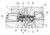
- the invention is illustrated in the drawing and is explained in more detail below. Show it: The single figure shows a section of a device according to the invention in cross section
- the device shown in the figure for sealing a gas channel (1,1 ') consisting essentially of sliding rings (2 ', 3') with an annular body (4 ') work together.
- a cross-sectional view is shown in the area of a Steering knuckle (5) of a motor vehicle. Air is used to fill the tires with a filling system, not shown, the air into the tires via a gas channel (1,1 ') (not shown) performed. Since the gas channel (1,1 ') has two rotating relative to each other Machine parts leads, namely the stationary steering knuckle (5), and the rotating Wheel hub (6), there is a seal of the gas channel (1,1 ') between these components necessary.
- an annular body (4 ') with a machine part for Example, the axle stub (5) is connected in a sealing and rotationally fixed manner. This can be done through a Press fit and sealing rings (7) take place.
- the ring body (4 ') acts on conical peripheral surfaces (9) on which Roll body (10 ') extend together with counter rings (2 ", 3").
- the slide rings (2 ', 3') also have tapered peripheral surfaces for receiving rolling elements (10 ').
- the ring body (4 ') has at least one opening (11') for the passage of air or a suitable gas.
- the ring body (4 ') faces axially aligned holes (12 ') or openings that act as a lubricating oil channel. On in this way it is ensured that the between the hub (6) and the steering knuckle (5) arranged bearings (13,13 ') can be provided with lubricant without additional oil channels must be inserted in the machine parts.
- the counter rings (2 ", 3") are radially offset from the sliding rings (2 ', 3'), so that the seal is depressurized or pressure-neutral.
Landscapes
- Engineering & Computer Science (AREA)
- Mechanical Engineering (AREA)
- Sealing Devices (AREA)
- Sealing Of Bearings (AREA)
Description
Aus der DE 4017788 A1 ist eine gattungsgemäße Vorrichtung bekannt. Der Ringkörper, über den das Gas in die Kraftfahrzeugreifen geleitet wird, fungiert als Gegelauffläche für die Gleitringe. Bei Druckbeaufschlagung werden die Gleitringe teilweise von dem Ringkörper weggedrückt. Die Vorrichtung ist deshalb für hohe Drücke nicht geeignet. Der Erfindung liegt die Aufgabe zugrunde ein Dichtungssystem zu schaffen, welches im Hinblick auf die Lebensdauer und auf das Abdichtungsvermögen eine Verbesserung zu gattungsgemäßen Abdichtvorrichtungen darstellt.
Die einzige Figur zeigt einen Ausschnitt einer erfindungsgemäßen Vorrichtung im Querschnitt
Claims (3)
- Vorrichtung zur Abdichtung eines Gaskanals zwischen zwei relativ zueinander rotierenden Maschinenteilen (5, 6) bei einer Reifendruckeinstellvorrichtung von Kraftfahrzeugen mit paarweise angeordneten, nach entgegengesetzten Seiten wirkenden Dichtungen, wobei die Dichtungen aus Gleitringen (2', 3') bestehen, die mit einem Ringkörper (4') zusammenwirken, welcher einem Maschinenteil (5) in dichter Verbindung steht und mindestens eine Öffnung (11') zur Durchführung des Gases aufweist, dadurch gekennzeichnet, daß der Ringkörper (4') auf jeder Seite eine zur Aufhahme eines einen Gegenring (2", 3") tragenden, elastischen Rollkörpers (10') bestimmte, kegelige Umfangsfläche (9) aufweist und die Gleitringe (2',3') gegenüber den Gegenringen (2",3") radial so versetzt sind, daß der Gasdruck im Gaskanal (1,1') keine negative Auswirkung auf die Dichtwirkung der Gleitringe (2',3') ausübt und die Gleitringe druckentlastet gelagert sind.
- Vorrichtung nach Anspruch 1, dadurch gekennzeichnet, daß jeder Gleitring (2',3') eine zur Aufnahme eines elastischen Rollkörpers (10') bestimmte, kegelige Umfangsfläche (9) aufweist.
- Vorrichtung nach den Ansprüchen 1 oder 2, dadurch gekennzeichent, daß der Ringkörper (4') mindestens eine axial gerichtete Bohrung (12') aufweist, die als Schmierölkanal fungiert.
Applications Claiming Priority (2)
| Application Number | Priority Date | Filing Date | Title |
|---|---|---|---|
| DE19523435A DE19523435C2 (de) | 1995-06-28 | 1995-06-28 | Vorrichtung zur Abdichtung eines Gaskanals |
| DE19523435 | 1995-06-28 |
Publications (2)
| Publication Number | Publication Date |
|---|---|
| EP0751016A1 EP0751016A1 (de) | 1997-01-02 |
| EP0751016B1 true EP0751016B1 (de) | 2000-03-08 |
Family
ID=7765424
Family Applications (1)
| Application Number | Title | Priority Date | Filing Date |
|---|---|---|---|
| EP96105322A Expired - Lifetime EP0751016B1 (de) | 1995-06-28 | 1996-04-03 | Vorrichtung zur Abdichtung eines Gaskanals |
Country Status (2)
| Country | Link |
|---|---|
| EP (1) | EP0751016B1 (de) |
| DE (1) | DE19523435C2 (de) |
Families Citing this family (3)
| Publication number | Priority date | Publication date | Assignee | Title |
|---|---|---|---|---|
| DE202004006136U1 (de) * | 2003-12-18 | 2005-05-04 | Liebherr-Werk Biberach Gmbh | Lagerdichtung und Lager |
| DE102013205399A1 (de) * | 2013-03-27 | 2014-10-02 | Robert Bosch Gmbh | Radnabenantrieb mit einem Planetengetriebe |
| DE102013207855B4 (de) * | 2013-04-30 | 2021-02-11 | Schaeffler Technologies AG & Co. KG | Lager mit Drehdurchführung sowie Reifendruckregelanlage mit einem derartigen Lager |
Family Cites Families (9)
| Publication number | Priority date | Publication date | Assignee | Title |
|---|---|---|---|---|
| GB865429A (en) * | 1958-01-09 | 1961-04-19 | Twin Disc Clutch Co | Fluid-cooled seal |
| GB879754A (en) * | 1959-12-14 | 1961-10-11 | Caterpillar Tractor Co | Seals and method of producing mating sealing surfaces |
| US3598147A (en) * | 1970-02-24 | 1971-08-10 | Nippon Piston Ring Co Ltd | Mechanisms for feeding air into a rotary member |
| GB1308833A (en) * | 1970-08-14 | 1973-03-07 | Caterpillar Tractor Co | Floating ring seal assembly |
| US4294454A (en) * | 1979-02-05 | 1981-10-13 | Cannings John A | Rotary seal unit |
| DE3206488A1 (de) * | 1982-02-23 | 1983-09-08 | M.A.N. Maschinenfabrik Augsburg-Nürnberg AG, 8000 München | "reifendruck-reguliervorrichtung" |
| DE3842451A1 (de) * | 1988-12-16 | 1990-06-21 | Burgmann Dichtungswerk Feodor | Gleitringdichtung |
| FR2644111B1 (fr) * | 1989-03-09 | 1991-12-06 | Bourgogne Essieux | Joint tournant pour pneumatiques |
| DE4017788A1 (de) * | 1990-06-01 | 1991-12-05 | Schlueter Anton Muenchen Gmbh | Druckluft-versorgungssystem |
-
1995
- 1995-06-28 DE DE19523435A patent/DE19523435C2/de not_active Expired - Fee Related
-
1996
- 1996-04-03 EP EP96105322A patent/EP0751016B1/de not_active Expired - Lifetime
Also Published As
| Publication number | Publication date |
|---|---|
| EP0751016A1 (de) | 1997-01-02 |
| DE19523435A1 (de) | 1997-01-09 |
| DE19523435C2 (de) | 1997-07-17 |
Similar Documents
| Publication | Publication Date | Title |
|---|---|---|
| EP1095799B1 (de) | Reifendruckregelanlage | |
| EP2613950B1 (de) | Reifendruckregelanlage mit drehdurchführung | |
| EP1981724B1 (de) | Dichtungsanordnung für eine reifendruck-reguliereinrichtung | |
| DE69220215T2 (de) | Radbefestigung für eine reifendruckregelungsanlage | |
| EP2810795B1 (de) | Drehdurchführung | |
| DE112014005076T5 (de) | Automatisches Reifenfüllsystem mit doppelter Pumpe für eine Lkw-Anordnung | |
| EP1874563B1 (de) | Vorrichtung, insbesondere drehdurchführung | |
| DE202015105702U1 (de) | Drehdurchführung einer Reifendruckregelanlage sowie Anordnung umfassend eine solche Drehdurchführung sowie eine auf einem Achsstummel gelagerte Nabe | |
| DE102017211574A1 (de) | Drehdurchführung für eine Reifenfüllanlage | |
| EP1338443A2 (de) | Drehdurchführung für eine Vorrichtung zum Füllen oder Entlüften eines Reifens eines Traktorrades | |
| DE68919633T2 (de) | Ein an einen Wälzlager angeordneter Dichtungsring zur Verbindung von zwei Fluidbehältern mit unterschiedlichem Druck, wobei wenigstens einer bezüglich des anderen drehbar ist. | |
| DE102013223512A1 (de) | Radantrieb mit Drehdurchführung | |
| EP0751016B1 (de) | Vorrichtung zur Abdichtung eines Gaskanals | |
| DE3206488C2 (de) | ||
| EP3713779B1 (de) | Dichtungsanordnung für eine drehdurchführung eines radlager eines kraftfahrzeugs | |
| DE102011014025B4 (de) | Fahrzeug, insbesondere Landmaschine | |
| EP1206656B1 (de) | Co 2 - kompressor | |
| DE102005006073A1 (de) | Vorrichtung, insbesondere Drehdurchführung | |
| DE827605C (de) | Anordnung an mit Luftreifen versehenen Fahrzeugraedern | |
| WO2014154422A1 (de) | Radnabenantrieb mit einem planetengetriebe | |
| DE10302444B4 (de) | Radlagerung für ein Fahrzeugrad | |
| DE102014221813B3 (de) | Einrichtung zur Einstellung des Luftdrucks eines an einer Fahrzeugachse über eine Felge angeordneten Luftreifens | |
| EP3882048B1 (de) | Fahrzeugrad-drehdurchführung, fahrzeugrad-baugruppe, selbstfahrende arbeitsmaschine und verfahren zum betrieb einer fahrzeugrad-drehdurchführung | |
| DE102017110480A1 (de) | Radlager für ein Kraftfahrzeug | |
| DE102012003152A1 (de) | Verbindungsmittel zum Zu- und/oder Abführen eines Mediums an einem Achsschenkel |
Legal Events
| Date | Code | Title | Description |
|---|---|---|---|
| PUAI | Public reference made under article 153(3) epc to a published international application that has entered the european phase |
Free format text: ORIGINAL CODE: 0009012 |
|
| AK | Designated contracting states |
Kind code of ref document: A1 Designated state(s): GB IT SE |
|
| 17P | Request for examination filed |
Effective date: 19970123 |
|
| 17Q | First examination report despatched |
Effective date: 19981023 |
|
| RAP3 | Party data changed (applicant data changed or rights of an application transferred) |
Owner name: FEDERAL-MOGUL BURSCHEID GMBH |
|
| GRAG | Despatch of communication of intention to grant |
Free format text: ORIGINAL CODE: EPIDOS AGRA |
|
| GRAG | Despatch of communication of intention to grant |
Free format text: ORIGINAL CODE: EPIDOS AGRA |
|
| GRAH | Despatch of communication of intention to grant a patent |
Free format text: ORIGINAL CODE: EPIDOS IGRA |
|
| RBV | Designated contracting states (corrected) |
Designated state(s): GB IT SE |
|
| REG | Reference to a national code |
Ref country code: DE Ref legal event code: 8566 |
|
| GRAH | Despatch of communication of intention to grant a patent |
Free format text: ORIGINAL CODE: EPIDOS IGRA |
|
| GRAA | (expected) grant |
Free format text: ORIGINAL CODE: 0009210 |
|
| AK | Designated contracting states |
Kind code of ref document: B1 Designated state(s): GB IT SE |
|
| PGFP | Annual fee paid to national office [announced via postgrant information from national office to epo] |
Ref country code: GB Payment date: 20000323 Year of fee payment: 5 |
|
| PGFP | Annual fee paid to national office [announced via postgrant information from national office to epo] |
Ref country code: SE Payment date: 20000420 Year of fee payment: 5 |
|
| ITF | It: translation for a ep patent filed | ||
| GBT | Gb: translation of ep patent filed (gb section 77(6)(a)/1977) |
Effective date: 20000417 |
|
| EN | Fr: translation not filed | ||
| PLBE | No opposition filed within time limit |
Free format text: ORIGINAL CODE: 0009261 |
|
| STAA | Information on the status of an ep patent application or granted ep patent |
Free format text: STATUS: NO OPPOSITION FILED WITHIN TIME LIMIT |
|
| 26N | No opposition filed | ||
| PG25 | Lapsed in a contracting state [announced via postgrant information from national office to epo] |
Ref country code: GB Free format text: LAPSE BECAUSE OF NON-PAYMENT OF DUE FEES Effective date: 20010403 |
|
| PG25 | Lapsed in a contracting state [announced via postgrant information from national office to epo] |
Ref country code: SE Free format text: LAPSE BECAUSE OF NON-PAYMENT OF DUE FEES Effective date: 20010404 |
|
| GBPC | Gb: european patent ceased through non-payment of renewal fee |
Effective date: 20010403 |
|
| EUG | Se: european patent has lapsed |
Ref document number: 96105322.0 |
|
| PG25 | Lapsed in a contracting state [announced via postgrant information from national office to epo] |
Ref country code: IT Free format text: LAPSE BECAUSE OF NON-PAYMENT OF DUE FEES;WARNING: LAPSES OF ITALIAN PATENTS WITH EFFECTIVE DATE BEFORE 2007 MAY HAVE OCCURRED AT ANY TIME BEFORE 2007. THE CORRECT EFFECTIVE DATE MAY BE DIFFERENT FROM THE ONE RECORDED. Effective date: 20050403 |