EP1874563B1 - Vorrichtung, insbesondere drehdurchführung - Google Patents
Vorrichtung, insbesondere drehdurchführung Download PDFInfo
- Publication number
- EP1874563B1 EP1874563B1 EP06743316A EP06743316A EP1874563B1 EP 1874563 B1 EP1874563 B1 EP 1874563B1 EP 06743316 A EP06743316 A EP 06743316A EP 06743316 A EP06743316 A EP 06743316A EP 1874563 B1 EP1874563 B1 EP 1874563B1
- Authority
- EP
- European Patent Office
- Prior art keywords
- sealing means
- channel
- chamber
- boundary surfaces
- tire
- Prior art date
- Legal status (The legal status is an assumption and is not a legal conclusion. Google has not performed a legal analysis and makes no representation as to the accuracy of the status listed.)
- Expired - Lifetime
Links
Images


Classifications
-
- B—PERFORMING OPERATIONS; TRANSPORTING
- B60—VEHICLES IN GENERAL
- B60C—VEHICLE TYRES; TYRE INFLATION; TYRE CHANGING; CONNECTING VALVES TO INFLATABLE ELASTIC BODIES IN GENERAL; DEVICES OR ARRANGEMENTS RELATED TO TYRES
- B60C23/00—Devices for measuring, signalling, controlling, or distributing tyre pressure or temperature, specially adapted for mounting on vehicles; Arrangement of tyre inflating devices on vehicles, e.g. of pumps or of tanks; Tyre cooling arrangements
- B60C23/001—Devices for manually or automatically controlling or distributing tyre pressure whilst the vehicle is moving
- B60C23/003—Devices for manually or automatically controlling or distributing tyre pressure whilst the vehicle is moving comprising rotational joints between vehicle-mounted pressure sources and the tyres
-
- F—MECHANICAL ENGINEERING; LIGHTING; HEATING; WEAPONS; BLASTING
- F16—ENGINEERING ELEMENTS AND UNITS; GENERAL MEASURES FOR PRODUCING AND MAINTAINING EFFECTIVE FUNCTIONING OF MACHINES OR INSTALLATIONS; THERMAL INSULATION IN GENERAL
- F16J—PISTONS; CYLINDERS; SEALINGS
- F16J15/00—Sealings
- F16J15/002—Sealings comprising at least two sealings in succession
-
- F—MECHANICAL ENGINEERING; LIGHTING; HEATING; WEAPONS; BLASTING
- F16—ENGINEERING ELEMENTS AND UNITS; GENERAL MEASURES FOR PRODUCING AND MAINTAINING EFFECTIVE FUNCTIONING OF MACHINES OR INSTALLATIONS; THERMAL INSULATION IN GENERAL
- F16J—PISTONS; CYLINDERS; SEALINGS
- F16J15/00—Sealings
- F16J15/16—Sealings between relatively-moving surfaces
- F16J15/32—Sealings between relatively-moving surfaces with elastic sealings, e.g. O-rings
- F16J15/3284—Sealings between relatively-moving surfaces with elastic sealings, e.g. O-rings characterised by their structure; Selection of materials
- F16J15/3288—Filamentary structures, e.g. brush seals
Definitions
- the invention relates to a device, in particular rotary feedthrough for a Reifenbehellstrom, with a rotatable about a rotation axis and a first interface having body, fixed relative to the rotatable body and a second interface having body, at least one formed between the rotatable body and the fixed body chamber wherein the at least one chamber is bounded by the interfaces of the bodies and by at least two sealing means guided between the interfaces, and at least one channel formed in the fixed and rotatable bodies and opening into the at least one chamber between the sealing means.
- Agricultural vehicles are often equipped with tire pressure control systems that can reduce tire pressure while driving on field work to ensure lower ground pressure and increase it when driving on the road. Furthermore, the tire pressure can be adapted to different load conditions and the wear of the tire can be reduced.
- compressed air is fed to the wheels via a rotary union provided in the axle arrangement for filling the tire.
- the DE 199 50 191 C1 discloses a tire pressure control system with a generic rotary feedthrough for transmitting a pressure medium from a relative to a rotatably mounted wheel fixed part of the vehicle on the rotatably mounted wheel.
- the rotary feedthrough has at least one chamber, which by a stator and by a rotor side concentric to Rotary axis of the wheel arranged annular body is limited.
- controllable sealing rings are inserted between the stator-side and the rotor-side annular body via a control line.
- the stator-side annular body and the rotor-side annular body are arranged side by side relative to the axis of rotation of the wheel, wherein a movement gap is left between the annular bodies.
- annular grooves In the stator-side annular body concentric with the sealing rings fitted annular grooves are introduced, wherein the annular grooves are connected to a loadable with a pressure medium control line. About a guided in the annular grooves control pressure, the sealing rings can be moved toward the rotor-side annular body and pressed, whereby the chamber is closed. When the chamber is closed, a pressure medium exchange can then take place via channels opening into the chamber. In unpressurized condition, the rotary feedthrough operates without contact.
- the disadvantage is that the control pressure device required to close the chamber is complicated and expensive. Furthermore, in the realization of such rotary joints on agricultural vehicles, such. As tractors, relatively large diameter of the sealing surfaces required, whereby high relative velocities occur, which are associated with considerable wear. Beyond this problem of wear, the seals must be able to compensate for mechanical deformations and to tolerate changes in the geometry to be sealed.
- the object underlying the invention is seen to provide a device suitable for a Reifenbehellstrom device with which one or more of the problems mentioned are overcome.
- a device of the type mentioned is formed such that the sealing means are formed as brush seals.
- the boundary surfaces of the bodies are arranged substantially facing one another, so that the sealing means together with the boundary surfaces form a chamber closed over the circumference of the axis of rotation, the volume of the chamber being determined by the spacings between the interfaces or the sealing means.
- Brush seals are known per se and are used especially in the field of compressors because they have less leakage than non-contact seals (so-called gap seals). Brush seals are contacting seals whose core is a highly flexible sealing element consisting of a plurality of wires, fibers or filaments, or a combination thereof, and adaptively conforming to a surface to be sealed.
- Brush seals can thereby compensate for changes in a sealing gap, for example in rotor movements, almost wear-free.
- Conventional brush seals are produced, for example, by a welding method in which a sealing arrangement of wires is stretched between two ring elements and welded to the ring elements via a circumferential weld.
- Novel methods of making brush seals enable the use of plastic fibers.
- the brush wires or fibers are placed around an annular core (carrier wire) and clamped by means of a clamping tube on the core.
- Such brush seals for example developed and manufactured by the company MTU.
- Brush seals have significant advantages over conventional seals used in tire inflation systems. Compared with non-contact seals, brush seals have the advantage of being virtually wear-free. They have a significantly higher sealing effect compared to non-contact seals, ie at comparable pressure difference their length (contact surface) is significantly lower. Brush seals work more reliably than conventional non-contact seals even with a relative movement between a rotating and a stationary seal part. At shaft standstill or at low speeds, the brushes are in contact with the relatively moving sealing surface, so that then a reliable seal of the chamber is ensured. At higher speeds, the brushes lift off due to aerodynamic forces. As a result, the wear is greatly reduced, resulting in very long service life.
- a rotary feedthrough which allows a transfer of a pressure medium from a channel via the chamber in the opposite channel, without having to interrupt the rotational movement of the rotatable body.
- several channels open into a chamber, whereby the total volume flow of a pressure medium supply can be increased and thereby filling or emptying times are reduced.
- several chambers can be formed by arranging further sealing means or brush seals.
- the first chamber is divided into two chambers.
- these chambers can also be formed completely separate from one another or even a third chamber can be formed, or a chamber can be subdivided into three chambers by two dividing sealing means.
- each of the chambers can lead channels through which a pressure for almost complete sealing of the chambers from the environment can be established.
- three sealing means are arranged, by which two chambers are delimited.
- depressions are formed on at least one of the boundary surfaces of the body, by means of which the sealing means, fixed in position or positionally limited positionable between the interfaces.
- the sealing means are preferably inserted or fitted into the recesses.
- the depressions are preferably designed as annular grooves arranged concentrically to the axis of rotation of the wheel and extend coaxially to the axis of rotation over the entire circumference of an interface.
- the arrangement of annular grooves for fixing the sealing means is only one possible embodiment.
- the sealing means can of course also be fixed or fastened in another way at the interface.
- Brush seals made of metallic and / or non-metallic fibers or threads are suitable for use according to the invention in a rotary feedthrough for a tire ventilation system.
- various fiber or thread-like materials can be used, which have a sufficient deformability with sufficient rigidity.
- brush seals having a plurality of bundled metal wires may be used, or brush seals having bundled fibers of ceramics or plastics.
- the channels arranged in the stationary body and the rotatable body can be designed as pressure-medium-operated discharge or supply lines. So can over the in the fixed body arranged channel pressure medium, such as compressed air, out into the chamber and transferred into the channel formed in the rotatable body.
- a further channel may be formed which serves, for example, as a control line for a fluid-operated switching element.
- the rotatable body is connected to a wheel provided with an air-inflatable tire.
- the trained on the rotatable body channel leads into a cavity surrounded by the tire or it is connected to the cavity of the tire, which is filled with, for example, air or gas.
- the channel connected to the cavity of the tire can serve both as a filling line and as an emptying line.
- a trained as a control line channel is preferably connected to a controllable by pressure medium valve.
- the rotatable body or located on the rotatable body components may be equipped with such a valve and connected via the control line or open or closed. It is also conceivable to switch other pressure-medium-operated switching means, for example pressure switches, via such a control line.
- a channel designed as a control line can serve, for example, to open a valve against a closing pressure acting on the valve and closing the valve, so that, for example, a tire filled with air can be emptied by opening the valve via the control line.
- At least one channel is connected to a pressure medium source, which is for pressurizing an am rotatable body located component, such as a tire, pressure medium required promotes.
- a pressure medium source which is for pressurizing an am rotatable body located component, such as a tire, pressure medium required promotes.
- a compressed air pump or a compressed air compressor is used.
- the fixed body is preferably connected to a fixed axle funnel or rotatably supported on the axle funnel, so that a connection between the compressed air lines and provided at the Achstrichter connection to a compressed air supply.
- the fixed body is preferably connected via torque arms in the form of connecting pins, connecting straps or other connecting elements with the axle funnel.
- the interfaces forming the chambers are arranged such that they extend radially to the axis of rotation and in the circumferential direction, so that the fibers or threads of the brush seals are aligned substantially parallel to the axis of rotation.
- the boundary surfaces forming the chambers are arranged such that they extend axially to the rotation axis and in the circumferential direction, so that the fibers or threads of the brush seals are aligned substantially radially to the axis of rotation.
- a device according to the invention is preferably provided on a vehicle, in particular an agricultural tractor.
- a vehicle in particular an agricultural tractor.
- commercial vehicles and machinery from the field of agriculture, construction and forestry be equipped with such devices to realize a tire inflation pressure system.
- trucks or buses such devices are suitable.
- a device according to the invention as part of a tire filling system allows the tire pressure to be adapted quickly and precisely to the operating conditions (ground condition, load weight, etc.) while driving.
- Fig. 1 shows an agricultural tractor 10 having a frame 12, a cab 13, a rear axle assembly 14 and a front axle assembly 16.
- the axle assemblies have rear wheels 18 and front wheels 20, respectively.
- the wheels 18, 20 each have a rim construction 22 with a wheel disc 24 and a tire 26, wherein the wheel discs 24 via Threaded bolt 25 are connected to the axle assemblies 14, 16 concentric with the axis of rotation 27 arranged wheel hubs 28.
- the rear axle assembly 14 is provided with a device 30 according to the invention, which is designed as a rotary feedthrough of a Reifenbehellstrom (not shown).
- Such a device 30 is in the in FIG. 1 illustrated embodiment provided on both sides of the rear axle assembly 14, wherein such devices 30 are also used on the front axle assembly 16.
- the device 30 comprises a fixed annular body or stator 32 and a rotatable annular body or rotor 34 and is in a first embodiment in FIG. 2 shown.
- the stator 32 is supported in a manner not shown on a a drive train (not shown) of the tractor 10 surrounding axle 36.
- the wheel 18 is supported by bearing assemblies (not shown) that extend between the axle body 36 and the wheel hub 28.
- the rotor 34 is mounted on the wheel hub 28 and fixedly connected to this, for example via screw 37 (not shown in detail) with the wheel disc 24.
- the hub 28 is the drive side with the drive train (not shown) of the tractor 10 and the output side with the wheel disc 24 is connected.
- a first channel 46 is formed, which opens in a rectangular course, starting from an axis of rotation 27 substantially radial extent, at a substantially radially to the axis of rotation 27 extending first interface 48, wherein the first interface 48 to the drive side of the tractor 10 directed outer surface of the Rotor 34 represents. In its direction proceeding from the interface 48, the first channel 46 opens into a pressure-controllable tire valve 47 or connects to the tire 26.
- a second channel 50 is formed, which likewise opens at the first interface 48 in a right-angled course, starting from an extension which is substantially radial with respect to the axis of rotation 27.
- the second passage 50 opens into the tire valve 47 and constitutes a control line for opening the tire valve 47, so that the tire valve 47 can be opened via the second passage 50 in a pressure-medium-controlled manner.
- a third channel 52 extending essentially axially to the axis of rotation 27 is formed, which terminates at a second boundary surface 54 extending essentially radially to the axis of rotation 27, wherein the second boundary surface 54 represents an outer surface of the stator 34 facing the output side of the tractor 10 ,
- a movement gap 57 is formed, so that the rotor 32 can rotate freely relative to the stator 34.
- the second interface 54 on the stator 32 has depressions 58, 60, 62 which extend axially relative to the axis of rotation 27 and are arranged concentrically with respect to the axis of rotation 27, wherein the recesses 58, 60, 62 each form an annular groove formed over the circumference of the stator 32.
- the design of the recesses 58, 60, 62 is chosen so that the annular grooves formed by the recesses 58, 60, 62 have different average radii to the axis of rotation 27.
- three recesses 58, 60, 62 are formed on the second interface 54, wherein the annular groove formed by the recess 58 has the largest average radius and the annular groove formed by the recess 62 has the smallest average radius.
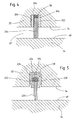
- FIG. 4 shows FIG. 4 in that the sealing means 104 has a first and a second annular disc 200, 202. Between the washers 200, 202, a plurality of fibers or wire strands 204 are arranged, which are made of thin metal wires. By means of a weld 206, the wire threads 204 are welded together and with the two annular discs 200, 202. The ring disks 200, 202 simultaneously serve as support disks for supporting the wire threads 204.
- the annular disks 200, 202, the weld 206 and the multiplicity of wire threads 204 are dimensioned such that they form a fit with the depressions 58 and can be fixed there.
- the wire strands 204 extend in the axial direction to the rotation axis 27 to the first interface 48 on the rotor 34, so that the movement gap 57 formed between the interfaces 48, 54 is sealed by the wire strands 204.
- FIG. 5 An alternative embodiment of the sealing means 104 designed as a brush seal is shown in FIG FIG. 5 shown.
- a plurality of fibers or threads 220 are placed around a wire core formed as a ring 222 and clamped by a clamping ring 224 fixed to the wire core 222.
- ring profiles 226, 228 are laid, which clamp the clamping ring 224 and thus also the laid around the wire core 222 plurality of threads 220.
- the ring profiles 226, 228 serve as support disks for the threads 220 and as shims for the sealing means 104, wherein the ring profiles 226, 228 are dimensioned such that they form a fit with the recesses 58 and can be fixed there.
- the threads 220 extend in the axial direction to the rotation axis 27 to the first interface 48 on the rotor 34, so that the movement gap 57 formed between the interfaces 48, 54 is sealed by the threads 220.
- This embodiment has the advantage that the threads 220 are connected or fixed to one another by a clamping ring 224, so that a weld seam 206, according to the example of FIG. 4 , can be dispensed with.
- other non-metallic filaments 220 or fibers made of plastic or ceramic can be used.
- the axial spacing of the boundary surfaces 48, 54 relative to one another and the length of the threads 204, 220 of the sealing means 104 are selected such that the sealing means 104 sealingly abut the boundary surface 48 with the threads 204, 220.
- the trained as brush seals sealant 104 have a very low wear and have a very good sealing effect or low leakage due to the high thread or fiber density.
- the height Sealing effect also stops at relative speeds between stator 32 and rotor 34, with increasing rotational speed of the rotor 34, the leakage increases. Nevertheless, the sealing means 104 formed as brush seals work more reliably than conventional shaft seals or contacting seals.
- dimensional inaccuracies can be tolerated at the boundary surfaces 48 or at the sealing surfaces, since the fiber or fiber bundles 204, 220 of a brush seal can adapt to surface changes caused by dimensional inaccuracies.
- Brush seals produce a comparably good sealing effect without rotation, for example during the filling of a tire 26 of a stationary tractor 10.
- sealing means 104 is formed between the wells 58, 60, a tightly sealed first chamber 106 and between the wells 60, 62, a sealed second chamber 108, wherein the chambers 106, 108 radially through the sealing means 104th and axially bounded by the interfaces 48, 54.
- the first channel 46 and the third channel 52 open into the first chamber 106 and the second channel 50 and the fourth channel 56 open into the second chamber 108th
- the in the FIG. 2 illustrated device 30 serves as a rotary feedthrough for a Reifenbehellstrom on a tractor 10, wherein the implementation is carried out in the axial direction, ie the formed on the stator 32 and the rotor 34 interfaces 48, 54 are formed axially spaced from the axis of rotation 27.
- the formed in the stator 32 third channel 52 is connected to a pressure source 110, which is used to fill the tire 26 compressed air in the third channel 52nd promotes.
- the compressed air flows into the first chamber 106 and from there into the first channel 46.
- the rotor 34 can maintain its rotational movement relative to the stator 32.
- the tire valve 47 provided on the tire 26 opens under compressed air supply in the direction of the tire 26, so that compressed air can flow from the third channel 52, via the first chamber 106 and via the first channel 46 into the tire 28. Once the compressed air supply is interrupted by the third channel 52, the tire valve 47 closes automatically by the pressure acting on the tire 26 ago.
- the formed in the fixed part 32 fourth channel 56 is also connected to the pressure source 110, wherein the pressure source 110 is switched on only to empty the tire 26, so that for emptying the tire 26 compressed air is conveyed into the fourth channel 56.
- the compressed air flows into the second chamber 108 and from there into the second channel 50.
- the second channel 50 is connected to the tire valve 47 in such a way that the compressed air flowing into the second channel 50 opens the tire valve 47, so that the tire in the tire 26 can flow through the tire valve 47 into the first channel 46 and from there via the first chamber 106 into the third channel 52. From there, the air can be discharged through a vent valve (not shown) to the environment.
- the wheel valve 47 closes automatically under the pressure prevailing in the tire 26.
- the control of the pressure supply or the control of the vent valve by a suitable control device which is installed in the cab 13 of the tractor 10.
- FIG. 3 shows an alternative embodiment of a device 30 'for a rotary feedthrough of a Reifenbehellstrom.
- the device 30 ' represents an exemplary embodiment in which the rotary leadthrough takes place in a direction radial to the axis of rotation 27, ie, the boundary surfaces 48', 54 'formed on the stator 32' and the rotor 34 'are radially spaced from the axis of rotation 27.
- the functionality essentially resembles the functioning of the in FIG. 2 illustrated example, the individual differences are described below.
- the interface 48 ' is formed as an axially extending to the axis of rotation 27 and in the circumferential direction and radially outward boundary surface 48'.
- the interface 54 ' is formed as an axially to the rotation axis 27 and circumferentially extending and radially inwardly directed interface 54'.
- the sealing means 104 'designed as brush seals are designed in such a way that the threads 204' (or one corresponding to those in FIG FIG. 5 described embodiment of the threads 220) extend radially corresponding to the axis of rotation 27 in the direction of the interface 48 'of the rotor 34' and the interface 48 'seal, otherwise the sealing means 104' have a same function and property and a same structure, as the sealant 104 of the example FIG.
- the recesses 58 ', 60', 62 'for receiving or fixing the sealing means 104' are formed at the interface 54 'of the stator 32' and constitute three axially spaced apart from the axis of rotation 27 annular grooves extending over the entire circumference of the interface 54th 'extend.
- the channels 46 ', 50' formed in the rotor 34 ' have a U-shaped profile, so that the channels 46', 50 'open into the chambers 106', 108 'demarcated by the sealing means 104'.
- the rotor 34 ' is over in the same way For example, screw 37 'connected to the wheel disc 24 and with the hub 28.
- the stator 32 ' is also connected to the axle body 36 (not shown). The filling and emptying of the tire 26 is carried out in the same way as in the FIG. 2 illustrated example.
Landscapes
- Engineering & Computer Science (AREA)
- General Engineering & Computer Science (AREA)
- Mechanical Engineering (AREA)
- Sealing Devices (AREA)
- Tires In General (AREA)
- Peptides Or Proteins (AREA)
- Control Of Motors That Do Not Use Commutators (AREA)
- Gyroscopes (AREA)
Description
- Die Erfindung betrifft eine Vorrichtung, insbesondere Drehdurchführung für eine Reifenbefüllanlage, mit einem um eine Rotationsachse rotierbaren und eine erste Grenzfläche aufweisenden Körper, einem gegenüber dem rotierbaren Körper feststehenden und eine zweite Grenzfläche aufweisenden Körper, wenigstens einer zwischen dem rotierbaren Körper und dem feststehenden Körper ausgebildeten Kammer, wobei die wenigstens eine Kammer durch die Grenzflächen der Körper und durch wenigstens zwei zwischen den Grenzflächen geführte Dichtmittel begrenzt ist, und wenigstens einem in dem feststehenden und in dem rotierbaren Körper ausgebildeten und zwischen den Dichtmitteln in die wenigstens eine Kammer mündenden Kanal.
- Landwirtschaftliche Fahrzeuge werden oft mit Reifendruckregelanlagen ausgestattet, durch die der Reifendruck während der Fahrt bei Feldarbeiten zur Gewährleistung eines niedrigeren Bodendrucks verringert und bei Straßenfahrten wieder erhöht werden kann. Des Weiteren kann dadurch der Reifendruck an unterschiedliche Belastungszustände angepasst und der Verschleiß des Reifens reduziert werden. Bei landwirtschaftlichen Fahrzeugen wird dabei zur Befüllung des Reifens Druckluft über eine in der Achsanordnung enthaltene Drehdurchführung zu den Rädern geführt.
- Die
DE 199 50 191 C1 offenbart eine Reifendruckregelanlage mit einer gattungsgemäßen Drehdurchführung zur Übertragung eines Druckmittels von einem gegenüber einem drehbar gelagerten Rad feststehenden Teil des Fahrzeugs auf das drehbar gelagerte Rad. Die Drehdurchführung weist wenigstens eine Kammer auf, welche durch einen statorseitig und durch einen rotorseitig konzentrisch zur Drehachse des Rades angeordneten Ringkörper begrenzt ist. Zur Abdichtung der Kammer sind zwischen dem statorseitigen und dem rotorseitigen Ringkörper über eine Steuerleitung steuerbare Dichtringe eingesetzt. Der statorseitige Ringkörper und der rotorseitige Ringkörper sind bezogen auf die Drehachse des Rades nebeneinanderliegend angeordnet, wobei zwischen den Ringkörpern ein Bewegungsspalt belassen ist. In dem statorseitigen Ringkörper sind konzentrische mit den Dichtringen bestückte Ringnuten eingebracht, wobei die Ringnuten an eine mit einem Druckmittel beaufschlagbare Steuerleitung angeschlossen sind. Über einen in die Ringnuten geleiteten Steuerdruck können die Dichtringe in Richtung zum rotorseitigen Ringkörper hin bewegt und angedrückt werden, wodurch die Kammer geschlossen wird. Bei geschlossener Kammer kann dann über in die Kammer mündende Kanäle ein Druckmittelaustausch erfolgen. Im drucklosen Zustand arbeitet die Drehdurchführung berührungslos. Nachteilig wirkt sich aus, dass die zum Schließen der Kammer erforderliche Steuerdruckeinrichtung aufwändig und teuer ist. Des Weiteren sind bei der Realisierung derartiger Drehdurchführungen an landwirtschaftlichen Fahrzeugen, wie z. B. Ackerschleppern, relativ große Durchmesser der Dichtflächen erforderlich, wodurch hohe Relativgeschwindigkeiten auftreten, die mit einem erheblichen Verschleiß verbunden sind. Über diese Verschleißproblematik hinaus, müssen die Dichtungen in der Lage sein, mechanische Verformungen auszugleichen und entstehende Änderungen in der abzudichtenden Geometrie zu tolerieren. - Die der Erfindung zugrunde liegende Aufgabe wird darin gesehen, eine für eine Reifenbefüllanlage geeignete Vorrichtung zu schaffen, mit der ein oder mehrere der genannten Probleme überwunden werden.
- Die Aufgabe wird erfindungsgemäß durch die Lehre des Patentanspruchs 1 gelöst. Weitere vorteilhafte Ausgestaltungen und Weiterbildungen der Erfindung gehen aus den Unteransprüchen hervor.
- Erfindungsgemäß wird eine Vorrichtung der eingangs genannten Art derart ausgebildet, dass die Dichtmittel als Bürstendichtungen ausgebildet sind. Die Grenzflächen der Körper sind im Wesentlichen einander zugewandt angeordnet, so dass die Dichtmittel zusammen mit den Grenzflächen eine über den Umfang der Rotationsachse geschlossene Kammer ausbilden, wobei das Volumen der Kammer durch die Abstände zwischen den Grenzflächen bzw. den Dichtmitteln bestimmt wird. Bürstendichtungen sind an sich bekannt und werden speziell im Bereich von Verdichtern eingesetzt, da sie gegenüber berührungslosen Dichtungen (sogenannten Spaltdichtungen) eine geringere Leckage aufweisen. Bürstendichtungen sind berührende Dichtungen, dessen Kernstück ein hoch flexibles Dichtungselement ist, welches aus einer Vielzahl von Drähten, Fasern oder Fäden bzw. aus einer Kombination derer, besteht und sich adaptiv an eine zu dichtende Fläche anpasst. Bürstendichtungen können dadurch Änderungen eines Dichtspalts, beispielsweise bei Rotorbewegungen, nahezu verschleißfrei kompensieren. Konventionelle Bürstendichtungen werden beispielsweise über ein Schweißverfahren hergestellt, bei dem eine dichtende Anordnung von Drähten zwischen zwei Ringelementen gespannt und über eine Umfangsschweißnaht mit den Ringelementen verschweißt wird. Neuartige Verfahren zur Herstellung von Bürstendichtungen ermöglichen die Verwendung von Kunststofffasern. Dabei werden die Bürstendrähte oder -fasern um einen ringförmigen Kern (Trägerdraht) gelegt und mittels eines Klemmrohrs auf den Kern festgeklemmt. Derartige Bürstendichtungen werden beispielsweise von der Firma MTU entwickelt und gefertigt. Für weitere detaillierte Ausführungen zu Bürstendichtungen wird hiermit auf die "Engineering News" der Internetseite der MTU Aero Engines hingewiesen, insbesondere auf den Report "The MTU Brush Seal Design".
- Bürstendichtungen weisen gegenüber konventionellen Dichtungen, die bei Reifenbefüllanlagen eingesetzt werden entscheidende Vorteile auf. Gegenüber berührungslosen Dichtungen haben Bürstendichtungen den Vorteil nahezu verschleißfrei zu sein. Sie haben eine gegenüber berührungslosen Dichtungen deutlich höhere Dichtwirkung, d. h. bei vergleichbarer Druckdifferenz ist ihre Baulänge (Kontaktfläche) deutlich geringer. Bürstendichtungen arbeiten auch bei einer Relativbewegung zwischen einem rotierendem und einem stehendem Dichtungsteil zuverlässiger als konventionelle berührungslose Dichtungen. Bei Wellenstillstand bzw. bei geringen Drehzahlen stehen die Bürsten in Kontakt mit der relativbewegten Dichtfläche, so dass dann eine zuverlässige Abdichtung der Kammer gewährleistet wird. Bei höheren Drehzahlen heben die Bürsten aufgrund von aerodynamischen Kräften ab. Hierdurch wird der Verschleiß sehr stark reduziert, wodurch sehr hohe Standzeiten erreicht werden. Der Einsatz von Bürstendichtungen ermöglicht es somit, auf eine gesonderte Einrichtung zum Andrücken von Dichtungen, wie sie beispielsweise in der eingangs aufgeführten
DE 199 50 191 C1 beschrieben ist, zu verzichten und gleichzeitig eine hohe Dichtungseigenschaft zu erzielen. Damit entfällt auch ein aufwändiges Einbringen von druckbeaufschlagbaren Ringnuten zur Führung von Dichtmitteln, welches einer hohen Fertigungspräzision bedarf, wodurch ein geringerer Fertigungs- und Kostenaufwand erzielt wird. Der durch den wenigstens einen Kanal beaufschlagte Druck in der Kammer wird dabei durch die Bürstendichtungen gehalten, wobei die bei einer Bürstendichtung auftretende Leckage vernachlässigbar klein bzw. unwesentlich ist. Da die Kammer durch die Dichtmittel nahezu druckdicht geschlossen wird, kann ein Druckmittelaustausch durch die im rotierbaren und im feststehenden Körper angeordneten Kanäle erfolgen, während sich der rotierbare Teil gegenüber dem feststehenden Teil in Rotation befindet. Es wird eine Drehdurchführung geschaffen, die ein Überführen eines Druckmittels von einem Kanal über die Kammer in den gegenüberliegenden Kanal ermöglicht, ohne die Rotationsbewegung des rotierbaren Körpers unterbrechen zu müssen. Dabei können, ausgehend vom rotierbaren und vom feststehenden Körper, mehrere Kanäle in eine Kammer münden, wodurch der Gesamtvolumenstrom einer Druckmittelzuführung erhöht werden kann und dadurch Befüll- oder Entleerzeiten reduziert werden. - Zwischen den Grenzflächen können durch Anordnung von weiteren Dichtmitteln bzw. Bürstendichtungen mehrere Kammern ausgebildet sein. Beispielsweise wird durch Hinzufügen eines dritten Dichtmittels die erste Kammer in zwei Kammern unterteilt. Durch ein viertes Dichtmittel können diese Kammern auch völlig voneinander getrennt ausgebildet sein oder gar eine dritte Kammer gebildet werden, bzw. eine Kammer durch zwei teilende Dichtmittel in drei Kammern unterteilt werden. In jede der Kammern können dabei Kanäle führen, durch welche ein Druck zum nahezu vollständigen Abdichten der Kammern gegenüber der Umgebung aufgebaut werden kann. Vorzugsweise sind drei Dichtmittel angeordnet, durch welche zwei Kammern abgegrenzt werden. Der Einsatz von Bürstendichtungen bei Drehdurchführungen zur Reifenbefüllung, ermöglicht beispielsweise eine Drehdurchführung für einen Füllvolumenstrom für einen Reifen als auch eine Drehdurchführung für einen Schaltvolumenstrom für ein Reifenventil. Eine Kombination einer Drehdurchführung für einen Füllvolumenstrom mit einem elektrisch betätigbaren Reifenventil ist jedoch ebenfalls denkbar.
- In einer bevorzugten Ausgestaltung der Erfindung sind auf wenigstens einer der Grenzflächen der Körper Vertiefungen ausgebildet, durch welche die Dichtmittel, lagefixiert oder lagebegrenzt zwischen den Grenzflächen positionierbar sind. Die Dichtmittel werden dabei vorzugsweise in die Vertiefungen eingesetzt bzw. eingepasst. Die Vertiefungen sind vorzugsweise als zur Rotationsachse des Rades konzentrisch angeordnete Ringnuten ausgebildet und erstrecken sich koaxial zur Rotationsachse über den gesamten Umfang einer Grenzfläche. Die Anordnung von Ringnuten zur Fixierung der Dichtmittel stellt dabei nur eine mögliche Ausführungsform dar. Die Dichtmittel können selbstverständlich auch auf andere Weise an der Grenzfläche fixiert bzw. befestigt werden.
- Für einen erfindungsgemäßen Einsatz bei einer Drehdurchführung für eine Reifenbelüftungsanlage eignen sich Bürstendichtungen aus metallischen und/oder nicht-metallischen Fasern oder Fäden. Dabei können verschiedene faser- oder fadenartige Materialien eingesetzt werden, die eine genügende Verformbarkeit bei ausreichender Steifigkeit aufweisen. So können beispielsweise Bürstendichtungen, die eine Vielzahl von gebündelten Metalldrähten bzw. -fäden aufweisen, oder auch Bürstendichtungen mit gebündelten Fasern aus Keramik oder Kunststoffen eingesetzt werden.
Die in dem feststehenden Körper und dem rotierbaren Körper angeordneten Kanäle können als druckmittelbetriebene Abführ- oder Zuführleitungen ausgebildet sein. So kann über den in dem feststehenden Körper angeordneten Kanal Druckmittel, beispielsweise Druckluft, in die Kammer geführt und in den im rotierbaren Körper ausgebildeten Kanal überführt werden. Ferner kann ein weiterer Kanal ausgebildet sein, der beispielsweise als Steuerleitung für ein druckmittelbetriebenes Schaltelement dient. - In einem Ausführungsbeispiel ist der rotierbare Körper mit einem Rad verbunden, welches mit einem luftbefüllbaren Reifen versehen ist. Der an dem rotierbaren Körper ausgebildete Kanal führt dabei in einen vom Reifen umgebenen Hohlraum bzw. er ist mit dem Hohlraum des Reifens verbunden, der beispielsweise mit Luft oder Gas befüllbar ist. Der mit dem Hohlraum des Reifens verbundene Kanal kann dabei sowohl als Befüllleitung als auch als Entleerleitung dienen.
- Ein als Steuerleitung ausgebildeter Kanal ist vorzugsweise mit einem durch Druckmittel ansteuerbaren Ventil verbunden. Dabei können beispielsweise der rotierbare Körper oder sich auf dem rotierbaren Körper befindliche Bauteile mit einem derartigen Ventil ausgerüstet sein und über die Steuerleitung geschaltet bzw. geöffnet oder geschlossen werden. Es ist auch denkbar andere druckmittelbetriebene Schaltmittel, beispielsweise Druckschalter, über eine derartige Steuerleitung zu schalten. Ein als Steuerleitung ausgebildeter Kanal kann beispielsweise dazu dienen, ein Ventil entgegen einem am Ventil wirkenden und das Ventil verschließenden Schließdruck zu öffnen, so dass beispielsweise ein mit Luft befüllter Reifen durch Öffnen des Ventils über die Steuerleitung entleert werden kann.
- Wenigstens ein Kanal ist mit einer Druckmittelquelle verbunden, die das zur Druckbeaufschlagung eines am rotierbaren Körper befindlichen Bauteils, beispielsweise eines Reifens, benötigte Druckmittel fördert. Vorzugsweise wird hierzu eine Druckluftpumpe oder ein Druckluftkompressor eingesetzt.
- Der feststehende Körper ist vorzugsweise mit einem feststehenden Achstrichter verbunden bzw. drehfest am Achstrichter abgestützt, so dass eine Verbindung zwischen den Druckluftleitungen und einem am Achstrichter vorgesehenen Anschluss zu einer Druckluftversorgung erfolgt. Der feststehende Körper ist vorzugsweise über Drehmomentstützen in Form von Verbindungsstiften, Verbindungslaschen oder anderen Verbindungselementen mit dem Achstrichter verbunden.
- In einer bevorzugten Ausgestaltung der Erfindung sind die die Kammern bildenden Grenzflächen derart angeordnet, dass sie sich radial zur Rotationsachse und in Umfangsrichtung erstrecken, so dass die Fasern bzw. Fäden der Bürstendichtungen im Wesentlichen parallel zur Rotationsachse ausgerichtet sind.
- In einer alternativen Ausgestaltung der Erfindung sind die die Kammern bildenden Grenzflächen derart angeordnet, dass sie sich axial zur Rotationsachse und in Umfangsrichtung erstrecken, so dass die Fasern bzw. Fäden der Bürstendichtungen im Wesentlichen radial zur Rotationsachse ausgerichtet sind.
- Eine erfindungsgemäße Vorrichtung wird vorzugsweise an einem Fahrzeug, insbesondere einem landwirtschaftlichen Schlepper, vorgesehen. So können beispielsweise Nutzfahrzeuge und Maschinen aus dem Bereich der Land-, Bau- und Forstwirtschaft mit derartigen Vorrichtungen ausgerüstet sein, um eine Reifendruckfüllanlage zu realisieren. Auch für Lastkraftwagen oder Omnibusse sind derartige Vorrichtungen geeignet. Eine erfindungsgemäße Vorrichtung als Teil einer Reifenbefüllanlage ermöglicht während der Fahrt den Reifendruck schnell und präzise an die Betriebsverhältnisse (Bodenbeschaffenheit, Ladegewicht etc.) anzupassen.
- Anhand der Zeichnung, die ein Ausführungsbeispiel der Erfindung zeigt, werden nachfolgend die Erfindung sowie weitere Vorteile und vorteilhafte Weiterbildungen und Ausgestaltungen der Erfindung näher beschrieben und erläutert.
- Es zeigt:
- Fig. 1
- eine schematische Seitenansicht eines landwirtschaftlichen Schleppers mit einer erfindungsgemäßen Vorrichtung,
- Fig. 2
- eine schematische Querschnittsansicht der erfindungsgemäßen Vorrichtung aus
Figur 1 und - Fig. 3
- eine schematische Querschnittsansicht der erfindungsgemäßen Vorrichtung in einer alternative Ausführungsform.
-
Fig. 1 zeigt einen landwirtschaftlichen Schlepper 10 mit einem Rahmen 12, einer Kabine 13, einer hinteren Achsanordnung 14 und einer vorderen Achsanordnung 16. Die Achsanordnungen weisen hintere Räder 18 bzw. vordere Räder 20 auf. Die Räder 18, 20 weisen jeweils eine Felgenkonstruktion 22 mit einer Radscheibe 24 sowie einen Reifen 26 auf, wobei die Radscheiben 24 über Gewindebolzen 25 mit an den Achsanordnungen 14, 16 konzentrisch zur Rotationsachse 27 angeordneten Radnaben 28 verbunden sind. Die hintere Achsanordnung 14 ist mit einer erfindungsgemäßen Vorrichtung 30, die als Drehdurchführung einer Reifenbefüllanlage (nicht gezeigt) ausgebildet ist, versehen. Eine derartige Vorrichtung 30 ist bei dem inFigur 1 dargestellten Ausführungsbeispiel auf beiden Seiten der hinteren Achsanordnung 14 vorgesehen, wobei derartige Vorrichtungen 30 auch an der vorderen Achsanordnung 16 einsetzbar sind. - Die Vorrichtung 30 weist einen feststehenden ringförmigen Körper bzw. Stator 32 und einen rotierbaren ringförmigen Körper bzw. Rotor 34 auf und ist in einem ersten Ausführungsbeispiel in
Figur 2 dargestellt. Der Stator 32 stützt sich in nicht dargestellter Weise auf einem einen Antriebsstrang (nicht gezeigt) des Schleppers 10 umgebenden Achskörper 36 ab. Das Rad 18 wird von Lageranordnungen (nicht gezeigt), die sich zwischen dem Achskörper 36 und der Radnabe 28 erstrecken gehalten. Der Rotor 34 ist auf der Radnabe 28 gelagert und fest mit dieser verbunden, beispielsweise über Verschraubungen 37 (nicht im Detail gezeigt) mit der Radscheibe 24. Die Radnabe 28 ist antriebsseitig mit dem Antriebsstrang (nicht gezeigt) des Schleppers 10 und abtriebsseitig mit der Radscheibe 24 verbunden ist. - Im Rotor 34 ist ein erster Kanal 46 ausgebildet, der in einem rechtwinkligen Verlauf, ausgehend von einer zur Rotationsachse 27 im Wesentlichen radialen Erstreckung, an einer sich im Wesentlichen radial zur Rotationsachse 27 erstreckenden ersten Grenzfläche 48 mündet, wobei die erste Grenzfläche 48 eine zur Antriebsseite des Schleppers 10 gerichtete Außenfläche des Rotors 34 darstellt. In seiner von der Grenzfläche 48 fortführenden Richtung mündet der erste Kanal 46 in ein über Druck ansteuerbares Reifenventil 47 bzw. stellt eine Verbindung zum Reifen 26 her.
- Im Rotor 34 ist ein zweiter Kanal 50 ausgebildet, der in einem rechtwinkligen Verlauf, ausgehend von einer zur Rotationsachse 27 im Wesentlichen radialen Erstreckung, ebenfalls an der ersten Grenzfläche 48 mündet. In seiner von der Grenzfläche 48 fortführenden Richtung mündet der zweite Kanal 50 in das Reifenventil 47 und stellt eine Steuerleitung zum Öffnen des Reifenventils 47 dar, so dass das Reifenventil 47 über den zweiten Kanal 50 druckmittelgesteuert öffenbar ist.
- Im Stator 32 ist ein im Wesentlichen axial zur Rotationsachse 27 verlaufender dritter Kanal 52 ausgebildet, der an einer sich im Wesentlichen radial zur Rotationsachse 27 erstreckenden zweiten Grenzfläche 54 mündet, wobei die zweite Grenzfläche 54 eine zur Abtriebsseite des Schleppers 10 gerichtete Außenfläche des Stators 34 darstellt.
- Im feststehenden Körper 32 ist ein im Wesentlichen axial zur Rotationsachse 27 verlaufender vierter Kanal 56 ausgebildet, der ebenfalls an der zweiten Grenzfläche 54 mündet.
- Zwischen den Grenzflächen 48 und 54 ist eine Bewegungsspalt 57 ausgebildet, so dass der Rotor 32 gegenüber dem Stator 34 frei rotieren kann.
- Die zweite Grenzfläche 54 am Stator 32 weist sich axial zur Rotationsachse 27 erstreckende und konzentrisch zur Rotationsachse 27 angeordnete Vertiefungen 58, 60, 62 auf, wobei die Vertiefungen 58, 60, 62 jeweils eine über den Umfang des Stators 32 ausgebildete Ringnut bilden. Die Ausbildung der Vertiefungen 58, 60, 62 ist dabei so gewählt, dass die durch die Vertiefungen 58, 60, 62 ausgebildeten Ringnuten unterschiedliche Durchschnittsradien zur Rotationsachse 27 aufweisen. Bei dem in
Figur 2 dargestellten Beispiel sind auf der zweiten Grenzfläche 54 drei Vertiefungen 58, 60, 62 ausgebildet, wobei die durch die Vertiefung 58 ausgebildete Ringnut den größten Durchschnittsradius und die durch die Vertiefung 62 ausgebildete Ringnut den kleinsten Durchschnittsradius aufweist. - In den durch die Vertiefungen 58, 60, 62 ausgebildeten Ringnuten sind als Bürstendichtungen ausgebildete Dichtmittel 104 angeordnet. Derartige als Bürstendichtungen ausgebildete Dichtmittel 104 sind in den
Figuren 4 und 5 dargestellt. Eine erste Ausführungsform zeigtFigur 4 , in dem das Dichtmittel 104 eine erste und eine zweite Ringscheibe 200, 202 aufweist. Zwischen den Ringscheiben 200, 202 sind eine Vielzahl von Fasern oder Drahtfäden 204 angeordnet, die aus dünnen Metalldrähten gefertigt sind. Mittels einer Schweißnaht 206 werden die Drahtfäden 204 miteinander und mit den beiden Ringscheiben 200, 202 verschweißt. Die Ringscheiben 200, 202 dienen gleichzeitig als Stützscheiben zur Abstützung der Drahtfäden 204. Die Ringscheiben 200, 202, die Schweißnaht 206 sowie die Vielzahl von Drahtfäden 204 sind so bemessen, dass sie mit den Vertiefungen 58 eine Passung bilden und dort fixierbar sind. Die Drahtfäden 204 erstrecken sich in axialer Richtung zur Rotationsachse 27 bis zur ersten Grenzfläche 48 an dem Rotor 34, so dass der zwischen den Grenzflächen 48, 54 ausgebildete Bewegungsspalt 57 durch die Drahtfäden 204 abgedichtet wird. - Eine alternative Ausführungsform der als Bürstendichtung ausgebildeten Dichtmittel 104 ist in
Figur 5 dargestellt. Hierbei werden eine Vielzahl von Fasern oder Fäden 220 um einen als Ring ausgebildeten Drahtkern 222 gelegt und von einem Klemmring 224 fest auf den Drahtkern 222 geklemmt. Um den Klemmring 224 sind Ringprofile 226, 228 gelegt, die den Klemmring 224 und damit auch die um den Drahtkern 222 gelegte Vielzahl von Fäden 220 einspannen. Gleichzeitig dienen die Ringprofile 226, 228 als Stützscheiben für die Fäden 220 und als Passscheiben für das Dichtmittel 104, wobei die Ringprofile 226, 228 derart bemessen sind, dass sie mit den Vertiefungen 58 eine Passung bilden und dort fixierbar sind. Die Fäden 220 erstrecken sich in axialer Richtung zur Rotationsachse 27 bis zur ersten Grenzfläche 48 an dem Rotor 34, so dass der zwischen den Grenzflächen 48, 54 ausgebildete Bewegungsspalt 57 durch die Fäden 220 abgedichtet wird. Diese Ausführungsform hat den Vorteil, dass die Fäden 220 durch einen Klemmring 224 miteinander verbunden bzw. fixiert werden, so dass auf eine Schweißnaht 206, gemäß dem Beispiel aus inFigur 4 , verzichtet werden kann. Dadurch können auch andere, nicht metallische Fäden 220 oder Fasern aus Kunststoff oder Keramik verwendet werden. - In beiden der in den
Figuren 4 und 5 gezeigten Ausführungsbeispielen der Dichtmittel 104 sind der axiale Abstand der Grenzflächen 48, 54 zueinander bzw. die Länge der Fäden 204, 220 der Dichtmittel 104 derart gewählt, dass die Dichtmittel 104 mit den Fäden 204, 220 an der Grenzfläche 48 abdichtend anliegen. Die als Bürstendichtungen ausgebildeten Dichtmittel 104 weisen einen nur sehr geringen Verschleiß auf und besitzen aufgrund der hohen Faden- bzw. Faserdichte eine sehr gute Dichtwirkung bzw. geringe Leckage. Die hohe Dichtwirkung hält auch bei Relativgeschwindigkeiten zwischen Stator 32 und Rotor 34 an, wobei mit zunehmender Rotationsgeschwindigkeit des Rotors 34 die Leckage zunimmt. Dennoch arbeiten die als Bürstendichtungen ausgebildeten Dichtmittel 104 zuverlässiger als herkömmliche Wellendichtungen bzw. berührende Dichtungen. Insbesondere können Maßungenauigkeiten an den Grenzflächen 48 bzw. an den Dichtflächen toleriert werden, da die Faser- bzw. Fadenbündel 204, 220 einer Bürstendichtung sich der durch Maßungenauigkeiten hervorgerufenen Oberflächenänderungen anpassen können. Bürstendichtungen erzeugen ohne Rotation, beispielsweise bei der Befüllung eines Reifens 26 eines stehenden Schleppers 10 eine vergleichbar gute Dichtwirkung. - Durch die in den Vertiefungen 58, 60, 62 angeordneten Dichtmittel 104 wird zwischen den Vertiefungen 58, 60 eine dichtfeste erste Kammer 106 und zwischen den Vertiefungen 60, 62 eine dichtfeste zweite Kammer 108 ausgebildet, wobei die Kammern 106, 108 radial durch die Dichtmittel 104 und axial durch die Grenzflächen 48, 54 begrenzt werden. Der erste Kanal 46 sowie der dritte Kanal 52 münden dabei in die erste Kammer 106 und der zweite Kanal 50 sowie der vierte Kanal 56 münden in die zweite Kammer 108.
- Die in der
Figur 2 dargestellte Vorrichtung 30 dient als Drehdurchführung für eine Reifenbefüllanlage an einem Schlepper 10, wobei die Durchführung in axialer Richtung erfolgt, d.h. die an dem Stator 32 und dem Rotor 34 ausgebildeten Grenzflächen 48, 54 sind axial zur Rotationsachse 27 beabstandet ausgebildet. Der im Stator 32 ausgebildete dritte Kanal 52 ist mit einer Druckquelle 110 verbunden, die zum Befüllen des Reifens 26 Druckluft in den dritten Kanal 52 fördert. Die Druckluft strömt dabei in die erste Kammer 106 und von dort aus in den ersten Kanal 46. Während des Druckaufbaus bzw. der Druckluftzufuhr kann der Rotor 34 seine Drehbewegung bzw. Rotationsbewegung gegenüber dem Stator 32 beibehalten. Das am Reifen 26 vorgesehene Reifenventil 47 öffnet sich unter Druckluftzufuhr in Richtung des Reifens 26, so dass Druckluft aus dem dritten Kanal 52, über die erste Kammer 106 und über den ersten Kanal 46 in den Reifen 28 strömen kann. Sobald die Druckluftzufuhr von dem dritten Kanal 52 unterbrochen wird, schließt sich das Reifenventil 47 selbsttätig durch den vom Reifen 26 her wirkenden Druck. - Der im feststehenden Teil 32 ausgebildete vierte Kanal 56 ist ebenfalls mit der Druckquelle 110 verbunden, wobei die Druckquelle 110 nur zum Entleeren des Reifens 26 zugeschaltet wird, so dass zum Entleeren des Reifens 26 Druckluft in den vierten Kanal 56 gefördert wird. Die Druckluft strömt dabei in die zweite Kammer 108 und von dort aus in den zweiten Kanal 50. Der zweite Kanal 50 ist derart mit dem Reifenventil 47 verbunden, dass die in den zweiten Kanal 50 strömende Druckluft das Reifenventil 47 öffnet, so dass die im Reifen 26 enthaltene Luft durch das Reifenventil 47 in den ersten Kanal 46 und von dort aus über die erste Kammer 106 in den dritten Kanal 52 strömen kann. Von dort aus kann die Luft durch ein Entlüftungsventil (nicht gezeigt) an die Umgebung abgegeben werden. Sobald die Druckluftzufuhr zum vierten Kanal 56 wieder unterbrochen wird, schließt das Radventil 47 selbsttätig unter dem im Reifen 26 herrschenden Druck. Die Ansteuerung der Druckversorgung bzw. die Ansteuerung des Entlüftungsventils erfolgt durch eine geeignete Steuereinrichtung, die in der Kabine 13 des Schleppers 10 installiert ist.
-
Figur 3 zeigt ein alternatives Ausführungsbeispiel einer Vorrichtung 30' für eine Drehdurchführung einer Reifenbefüllanlage. Die Vorrichtung 30' stellt ein Ausführungsbeispiel dar, bei dem die Drehdurchführung in zur Rotationsachse 27 radialer Richtung erfolgt, d.h. die an dem Stator 32' und dem Rotor 34' ausgebildeten Grenzflächen 48', 54' sind radial zur Rotationsachse 27 beabstandet ausgebildet. Die Funktionsweise gleicht im Wesentlichen der Funktionsweise des inFigur 2 dargestellten Beispiels, wobei die einzelnen Unterschiede im Folgenden beschrieben sind. Die Grenzfläche 48' ist als eine sich axial zur Rotationsachse 27 und in Umfangsrichtung erstreckende und radial nach außen gerichtete Grenzfläche 48' ausgebildet. Die Grenzfläche 54' ist als eine sich axial zur Rotationsachse 27 und in Umfangsrichtung erstreckende und radial nach innen gerichtete Grenzfläche 54' ausgebildet. Ferner sind die als Bürstendichtungen ausgebildeten Dichtmittel 104' derart ausgebildet, dass die Fäden 204' (oder eine entsprechend der inFigur 5 beschriebene Ausführungsform der Fäden 220) sich entsprechend radial zur Rotationsachse 27 in Richtung der Grenzfläche 48' des Rotors 34' erstrecken und die Grenzfläche 48' abdichten, ansonsten weisen die Dichtmittel 104' eine gleiche Funktion und Eigenschaft sowie einen gleichen Aufbau auf, wie die Dichtmittel 104 des Beispiels ausFigur 2 . Die Vertiefungen 58', 60', 62' zur Aufnahme bzw. Fixierung der Dichtmittel 104' sind an der Grenzfläche 54' des Stators 32' ausgebildet und stellen drei axial zur Rotationsachse 27 beabstandete Ringnuten dar, die sich über den gesamten Umfang der Grenzfläche 54' erstrecken. Die im Rotor 34' ausgebildeten Kanäle 46', 50' weisen einen u-förmigen Verlauf auf, so dass die Kanäle 46', 50' in die durch die Dichtmittel 104' abgegrenzten Kammern 106', 108' münden. Der Rotor 34' ist auf gleiche Weise über beispielsweise Verschraubungen 37' mit der Radscheibe 24 bzw. mit der Radnabe 28 verbunden. Der Stator 32' ist auch hier mit dem Achskörper 36 verbunden (nicht gezeigt). Das Befüllen und Entleeren des Reifens 26 erfolgt auf gleiche Weise wie bei dem inFigur 2 dargestellten Beispiel. - Auch wenn die Erfindung lediglich anhand eines Ausführungsbeispiels beschrieben wurde, erschließen sich für den Fachmann im Lichte der vorstehenden Beschreibung sowie der Zeichnung viele verschiedenartige Alternativen, Modifikationen und Varianten, die unter die vorliegende Erfindung fallen. So kann beispielsweise auf die Anordnung der Kanäle 50, 56 bzw. 50', 56' verzichtet werden und ein elektrisch betriebenes Reifenventil 47 eingesetzt werden. Damit würde ein Dichtmittel 104 bzw. 104' und damit die Kammer 108 bzw. 108' entfallen und lediglich die Kammer 106 bzw. 106' zur Übertragung von Druckluft durch zwei angrenzende Dichtmittel 104 bzw. 104' abgedichtet werden.
Claims (12)
- Vorrichtung, insbesondere Drehdurchführung für eine Reifenbefüllanlage, mit einem um eine Rotationsachse (27) rotierbaren und eine erste Grenzfläche (48, 48') aufweisenden Körper (34, 34'), einem gegenüber dem rotierbaren Körper (34, 34') feststehenden und eine zweite Grenzfläche (54, 54') aufweisenden Körper (32, 32'), wenigstens einer zwischen dem rotierbaren Körper (34, 34') und dem feststehenden Körper (32, 32') ausgebildeten Kammer (106, 108, 106', 108'), wobei die wenigstens eine Kammer (106, 108, 106', 108') durch die Grenzflächen (48, 54, 48', 54') der Körper (34, 32, 34', 32') und durch wenigstens zwei sich zwischen den Grenzflächen (34, 32, 34', 32') erstreckende Dichtmittel (104, 104') begrenzt ist, und wenigstens einem in dem feststehenden und in dem rotierbaren Körper (32, 34, 32', 34') ausgebildeten und zwischen den Dichtmitteln (104, 104') in die wenigstens eine Kammer (106, 108, 106', 108') mündenden Kanal (46, 50, 52, 56, 46', 50', 52', 56'), dadurch gekennzeichnet, dass die Dichtmittel (104, 104') als Bürstendichtungen ausgebildet sind.
- Vorrichtung nach Anspruch 1, dadurch gekennzeichnet, dass zwischen der ersten und zweiten Grenzfläche (48, 54, 48', 54') eine oder mehrere weitere durch eine oder mehrere weitere Dichtmittel (104, 104') abgrenzbare Kammern (106, 108, 106', 108') ausgebildet sind.
- Vorrichtung nach einem der vorhergehenden Ansprüche, dadurch gekennzeichnet, dass auf wenigstens einer der Grenzflächen (48, 54, 48', 54') Vertiefungen (58, 60, 62, 58', 60', 62') ausgebildet sind, in welchen die Bürstendichtungen (104, 104'), lagefixiert zwischen den Grenzflächen (48, 54, 48', 54') geführt sind.
- Vorrichtung nach einem der vorhergehenden Ansprüche, dadurch gekennzeichnet, dass die Bürstendichtungen (104, 104'), metallische und/oder nicht-metallische Fasern oder Fäden aufweisen.
- Vorrichtung einem der vorhergehenden Ansprüche, dadurch gekennzeichnet, dass der wenigstens eine Kanal (46, 50, 52, 56, 46', 50', 52', 56') als eine druckmittelbetriebene Abführ- und/oder Zuführ- und/oder Steuerleitung ausgebildet ist.
- Vorrichtung nach einem der vorhergehenden Ansprüche, dadurch gekennzeichnet, dass der wenigstens eine Kanal (46, 50, 52, 56, 46', 50', 52', 56') mit einem mit Druckmittel befüllbaren Reifen (26) verbindbar ist.
- Vorrichtung nach einem der vorhergehenden Ansprüche, dadurch gekennzeichnet, dass der wenigstens eine Kanal (46, 50, 52, 56, 46', 50', 52', 56') mit einem durch Druckmittel ansteuerbaren Ventil (47) verbindbar ist.
- Vorrichtung nach einem der vorhergehenden Ansprüche, dadurch gekennzeichnet, dass der wenigstens eine Kanal (46, 50, 52, 56, 46', 50', 52', 56') mit einer Druckmittelquelle (110), insbesondere mit einer Druckluftquelle, verbindbar ist.
- Vorrichtung nach einem der vorhergehenden Ansprüche, dadurch gekennzeichnet, dass der feststehende Körper (32, 32') mit einem feststehenden Achskörper (36) verbunden ist.
- Vorrichtung nach einem der vorhergehenden Ansprüche, dadurch gekennzeichnet, dass die Grenzflächen (48, 54, 48', 54') sich radial zur Rotationsachse (27) erstrecken.
- Vorrichtung nach einem der Ansprüche 1 bis 9, dadurch gekennzeichnet, dass die Grenzflächen (48, 54, 48', 54') sich axial zur Rotationsachse (27) erstrecken.
- Fahrzeug mit einer Vorrichtung (30, 30') nach einem oder mehreren der vorhergehenden Ansprüche.
Applications Claiming Priority (2)
| Application Number | Priority Date | Filing Date | Title |
|---|---|---|---|
| DE102005018584A DE102005018584A1 (de) | 2005-04-21 | 2005-04-21 | Vorrichtung, insbesondere Drehdurchführung |
| PCT/EP2006/061634 WO2006111523A1 (de) | 2005-04-21 | 2006-04-18 | Vorrichtung, insbesondere drehdurchführung |
Publications (2)
| Publication Number | Publication Date |
|---|---|
| EP1874563A1 EP1874563A1 (de) | 2008-01-09 |
| EP1874563B1 true EP1874563B1 (de) | 2008-10-01 |
Family
ID=36574912
Family Applications (1)
| Application Number | Title | Priority Date | Filing Date |
|---|---|---|---|
| EP06743316A Expired - Lifetime EP1874563B1 (de) | 2005-04-21 | 2006-04-18 | Vorrichtung, insbesondere drehdurchführung |
Country Status (6)
| Country | Link |
|---|---|
| US (1) | US20090211682A1 (de) |
| EP (1) | EP1874563B1 (de) |
| AT (1) | ATE409603T1 (de) |
| BR (1) | BRPI0609412A2 (de) |
| DE (2) | DE102005018584A1 (de) |
| WO (1) | WO2006111523A1 (de) |
Families Citing this family (19)
| Publication number | Priority date | Publication date | Assignee | Title |
|---|---|---|---|---|
| DE202010008453U1 (de) * | 2010-09-06 | 2010-11-04 | Ptg Reifendruckregelsysteme Gmbh | Reifendruckregelanlage für ein Kraftfahrzeug sowie Drehdurchführung |
| DE102010054366A1 (de) * | 2010-12-13 | 2012-06-14 | Ludwig Volk | Reifendruckregelanlage |
| FR2978699B1 (fr) * | 2011-08-02 | 2014-02-28 | Nexter Mechanics | Dispositif d'etancheite tournant et bague d'etancheite pour un tel dispositif |
| DE202011051737U1 (de) | 2011-10-24 | 2011-11-04 | Ptg Reifendruckregelsysteme Gmbh | Drehdurchführung als Teil einer Reifendruckregelanlage eines Fahrzeuges |
| EP2836376B1 (de) | 2012-04-09 | 2020-03-04 | Dana Heavy Vehicle Systems Group, LLC | Reifenfüllanlage |
| US10059156B2 (en) | 2012-04-09 | 2018-08-28 | Dana Heavy Vehicle Systems Group, Llc | Hub assembly for a tire inflation system |
| DE102012216276A1 (de) | 2012-09-13 | 2014-03-13 | Zf Friedrichshafen Ag | Befüllsystem zur fahrzeugseitigen Innendruckregelung einer Bereifung eines Fahrzeugrades |
| DE102013105890A1 (de) | 2013-06-07 | 2014-12-11 | Claas Selbstfahrende Erntemaschinen Gmbh | Drehdurchführung |
| US9452644B2 (en) * | 2013-09-18 | 2016-09-27 | Arvinmeritor Technology, Llc | Tire inflation system with a passage for routing pressurized gas |
| DE102013223512A1 (de) * | 2013-11-19 | 2015-05-21 | Robert Bosch Gmbh | Radantrieb mit Drehdurchführung |
| WO2015195998A1 (en) | 2014-06-20 | 2015-12-23 | Dana Heavy Vehicle Systems Group, Llc | Rotary joint assembly |
| EP3075574B1 (de) | 2015-03-31 | 2017-11-08 | Meritor Heavy Vehicle Systems Cameri SpA | Aktuator |
| DE202015105859U1 (de) | 2015-11-04 | 2017-02-07 | Ptg Reifendruckregelsysteme Gmbh | Radventilanordnung sowie Reifendruckregelanlage mit wenigstens einer solchen Radventilanordnung |
| DE102015225291A1 (de) | 2015-12-15 | 2017-06-22 | Robert Bosch Gmbh | Radnabenantrieb |
| DE102015225355A1 (de) | 2015-12-16 | 2017-06-22 | Robert Bosch Gmbh | Radnabenantrieb mit einer Drehvorrichtung |
| ES2745326T3 (es) | 2017-05-12 | 2020-02-28 | Reinhold Schulte | Equipo de presurización para neumáticos |
| DE102021000192B3 (de) | 2021-01-18 | 2022-04-28 | Markus Rottmann | Kompakter Drehübertrager oder Drehdurchführung |
| US11117426B1 (en) | 2021-03-24 | 2021-09-14 | Ptg Reifendruckregelsysteme Gmbh | Rotary transmission leadthrough as part of a tire pressure control system |
| US12528318B2 (en) | 2022-05-27 | 2026-01-20 | Deere & Company | Compact rotary union assembly for a wheel hub |
Family Cites Families (14)
| Publication number | Priority date | Publication date | Assignee | Title |
|---|---|---|---|---|
| US885032A (en) * | 1907-06-24 | 1908-04-21 | Sebastian Ziani De Ferranti | Fluid packing. |
| US2634782A (en) * | 1950-10-30 | 1953-04-14 | Bendix Westinghouse Automotive | Tire inflation control system |
| US4498515A (en) * | 1983-10-03 | 1985-02-12 | Eaton Corporation | Onboard tire inflation system |
| US5253688A (en) * | 1991-09-12 | 1993-10-19 | Tigges & Winckel Bonumwerke | Tire pressure control system |
| DE19645163C2 (de) * | 1996-11-02 | 2000-10-05 | Mtu Muenchen Gmbh | Bürstendichtung für Rotor-Stator-Anordnung |
| DE19712088C2 (de) * | 1997-03-22 | 1999-06-24 | Mtu Muenchen Gmbh | Bürstendichtung mit in Umfangsrichtung schräg gestellten Borsten |
| DE19720648C2 (de) * | 1997-05-16 | 2000-07-13 | Mtu Muenchen Gmbh | Bürstendichtung mit Front- und Stützplatte |
| DE19937932C2 (de) * | 1999-08-11 | 2003-07-17 | Mtu Aero Engines Gmbh | Bürstendichtring |
| DE19950191C1 (de) * | 1999-10-19 | 2001-05-10 | Tigges & Winckel Bonumwerke | Reifendruckregelanlage |
| DE10044886B4 (de) * | 2000-09-12 | 2006-03-16 | Gkn Walterscheid Gmbh | Anordnung mit einem Rad und einer Vorrichtung zum Befüllen oder Entlüften eines Reifens eines Fahrzeugs, insbesondere Traktors |
| DE10208024B4 (de) * | 2002-02-26 | 2005-06-02 | Gkn Walterscheid Gmbh | Drehdurchführung für eine Vorrichtung zum Füllen oder Entlüften eines Reifens eines Traktorrades |
| US7677847B2 (en) * | 2002-03-26 | 2010-03-16 | Siemens Aktiengesellschaft | Sealing assembly for a spindle |
| DE10213530A1 (de) * | 2002-03-26 | 2003-10-09 | Siemens Ag | Bürstendichtung zur Medienübergabe in Werkzeugmaschinen |
| ITPI20030008A1 (it) * | 2003-01-23 | 2004-07-24 | Angelo Fusco | Mozzo coassiale a tenuta pneumatica adibito al ripristino |
-
2005
- 2005-04-21 DE DE102005018584A patent/DE102005018584A1/de not_active Withdrawn
-
2006
- 2006-04-18 EP EP06743316A patent/EP1874563B1/de not_active Expired - Lifetime
- 2006-04-18 BR BRPI0609412-0A patent/BRPI0609412A2/pt not_active Application Discontinuation
- 2006-04-18 DE DE502006001692T patent/DE502006001692D1/de not_active Expired - Lifetime
- 2006-04-18 WO PCT/EP2006/061634 patent/WO2006111523A1/de not_active Ceased
- 2006-04-18 AT AT06743316T patent/ATE409603T1/de active
- 2006-04-18 US US11/918,759 patent/US20090211682A1/en not_active Abandoned
Also Published As
| Publication number | Publication date |
|---|---|
| ATE409603T1 (de) | 2008-10-15 |
| BRPI0609412A2 (pt) | 2011-10-11 |
| US20090211682A1 (en) | 2009-08-27 |
| DE102005018584A1 (de) | 2006-10-26 |
| DE502006001692D1 (de) | 2008-11-13 |
| EP1874563A1 (de) | 2008-01-09 |
| WO2006111523A1 (de) | 2006-10-26 |
Similar Documents
| Publication | Publication Date | Title |
|---|---|---|
| EP1874563A1 (de) | Vorrichtung, insbesondere drehdurchführung | |
| EP1981724B1 (de) | Dichtungsanordnung für eine reifendruck-reguliereinrichtung | |
| EP2613950B1 (de) | Reifendruckregelanlage mit drehdurchführung | |
| DE19950191C1 (de) | Reifendruckregelanlage | |
| DE19915022B4 (de) | Elastomerdichtung zwischen einem Kolben und einem Zylinder und/oder einem Schaft eines automatischen Kraftfahrzeuggetriebes | |
| EP3424755B1 (de) | Drehdurchführung für eine reifenfüllanlage | |
| EP2810795B1 (de) | Drehdurchführung | |
| DE102012006901B3 (de) | Drehdurchführung | |
| DE102004021161A1 (de) | Drehdurchführung einer Reifendruckregelung | |
| EP0377561B1 (de) | Reifendruckregelanlage für kraftfahrzeuge, insbesondere für ackerschlepper | |
| DE102011014025B4 (de) | Fahrzeug, insbesondere Landmaschine | |
| DE102019112320A1 (de) | Drehübertragunsvorrichtung zum übertragen von steuer- und/oder arbeitsdrücken zu einem zumindest bereichsweise im inneren einer welle aufgenommenen oder ausgebildeten fluidkanal | |
| DE102005006073A1 (de) | Vorrichtung, insbesondere Drehdurchführung | |
| EP1488941B1 (de) | Luftdichte, koaxiale Radnabe zum Regulieren des internen Reifendrucks während der Fahrt | |
| DE10302444B4 (de) | Radlagerung für ein Fahrzeugrad | |
| DE102021101246A1 (de) | Vorrichtung zum übertragen von druckluft oder steuer- und/oder arbeitsdrücken in einer gelenkwellenanordnung | |
| EP2837512A1 (de) | Radaufhängung | |
| EP3882048B1 (de) | Fahrzeugrad-drehdurchführung, fahrzeugrad-baugruppe, selbstfahrende arbeitsmaschine und verfahren zum betrieb einer fahrzeugrad-drehdurchführung | |
| EP2151593B1 (de) | Dichtung für eine Radnabe | |
| DE102013203680A1 (de) | Drehdurchführung und Reifendruckregulierungsanlage mit Drehdurchführung | |
| DE202020101527U1 (de) | Fahrzeugrad-Drehdurchführung, Fahrzeugrad-Baugruppe und selbstfahrende Arbeitsmaschine | |
| DE102015218414A1 (de) | Gelenklager, antreibbare Lenkachse sowie Mobilbagger | |
| DE102014219980B4 (de) | Anordnung zur Druckluftversorgung eines Rades eines Fahrzeuges | |
| DE202024105459U1 (de) | Drehdurchführung als Teil einer Reifendruckregelanlage eines Fahrzeuges sowie damit ausgerüstetes Fahrzeug | |
| DE202023107206U1 (de) | Drehgelenkbaugruppe zur Bereitstellung eines Reifenfüllsystems |
Legal Events
| Date | Code | Title | Description |
|---|---|---|---|
| PUAI | Public reference made under article 153(3) epc to a published international application that has entered the european phase |
Free format text: ORIGINAL CODE: 0009012 |
|
| 17P | Request for examination filed |
Effective date: 20071121 |
|
| AK | Designated contracting states |
Kind code of ref document: A1 Designated state(s): AT BE BG CH CY CZ DE DK EE ES FI FR GB GR HU IE IS IT LI LT LU LV MC NL PL PT RO SE SI SK TR |
|
| GRAP | Despatch of communication of intention to grant a patent |
Free format text: ORIGINAL CODE: EPIDOSNIGR1 |
|
| DAX | Request for extension of the european patent (deleted) | ||
| GRAS | Grant fee paid |
Free format text: ORIGINAL CODE: EPIDOSNIGR3 |
|
| GRAA | (expected) grant |
Free format text: ORIGINAL CODE: 0009210 |
|
| AK | Designated contracting states |
Kind code of ref document: B1 Designated state(s): AT BE BG CH CY CZ DE DK EE ES FI FR GB GR HU IE IS IT LI LT LU LV MC NL PL PT RO SE SI SK TR |
|
| REG | Reference to a national code |
Ref country code: GB Ref legal event code: FG4D Free format text: NOT ENGLISH |
|
| REG | Reference to a national code |
Ref country code: CH Ref legal event code: EP |
|
| REG | Reference to a national code |
Ref country code: IE Ref legal event code: FG4D Free format text: LANGUAGE OF EP DOCUMENT: GERMAN |
|
| REF | Corresponds to: |
Ref document number: 502006001692 Country of ref document: DE Date of ref document: 20081113 Kind code of ref document: P |
|
| REG | Reference to a national code |
Ref country code: SE Ref legal event code: TRGR |
|
| PG25 | Lapsed in a contracting state [announced via postgrant information from national office to epo] |
Ref country code: SI Free format text: LAPSE BECAUSE OF FAILURE TO SUBMIT A TRANSLATION OF THE DESCRIPTION OR TO PAY THE FEE WITHIN THE PRESCRIBED TIME-LIMIT Effective date: 20081001 |
|
| NLV1 | Nl: lapsed or annulled due to failure to fulfill the requirements of art. 29p and 29m of the patents act | ||
| REG | Reference to a national code |
Ref country code: IE Ref legal event code: FD4D |
|
| PG25 | Lapsed in a contracting state [announced via postgrant information from national office to epo] |
Ref country code: BG Free format text: LAPSE BECAUSE OF FAILURE TO SUBMIT A TRANSLATION OF THE DESCRIPTION OR TO PAY THE FEE WITHIN THE PRESCRIBED TIME-LIMIT Effective date: 20090101 Ref country code: ES Free format text: LAPSE BECAUSE OF FAILURE TO SUBMIT A TRANSLATION OF THE DESCRIPTION OR TO PAY THE FEE WITHIN THE PRESCRIBED TIME-LIMIT Effective date: 20090112 Ref country code: LT Free format text: LAPSE BECAUSE OF FAILURE TO SUBMIT A TRANSLATION OF THE DESCRIPTION OR TO PAY THE FEE WITHIN THE PRESCRIBED TIME-LIMIT Effective date: 20081001 |
|
| PG25 | Lapsed in a contracting state [announced via postgrant information from national office to epo] |
Ref country code: LV Free format text: LAPSE BECAUSE OF FAILURE TO SUBMIT A TRANSLATION OF THE DESCRIPTION OR TO PAY THE FEE WITHIN THE PRESCRIBED TIME-LIMIT Effective date: 20081001 Ref country code: NL Free format text: LAPSE BECAUSE OF FAILURE TO SUBMIT A TRANSLATION OF THE DESCRIPTION OR TO PAY THE FEE WITHIN THE PRESCRIBED TIME-LIMIT Effective date: 20081001 Ref country code: PT Free format text: LAPSE BECAUSE OF FAILURE TO SUBMIT A TRANSLATION OF THE DESCRIPTION OR TO PAY THE FEE WITHIN THE PRESCRIBED TIME-LIMIT Effective date: 20090302 Ref country code: PL Free format text: LAPSE BECAUSE OF FAILURE TO SUBMIT A TRANSLATION OF THE DESCRIPTION OR TO PAY THE FEE WITHIN THE PRESCRIBED TIME-LIMIT Effective date: 20081001 Ref country code: IS Free format text: LAPSE BECAUSE OF FAILURE TO SUBMIT A TRANSLATION OF THE DESCRIPTION OR TO PAY THE FEE WITHIN THE PRESCRIBED TIME-LIMIT Effective date: 20090201 |
|
| PG25 | Lapsed in a contracting state [announced via postgrant information from national office to epo] |
Ref country code: DK Free format text: LAPSE BECAUSE OF FAILURE TO SUBMIT A TRANSLATION OF THE DESCRIPTION OR TO PAY THE FEE WITHIN THE PRESCRIBED TIME-LIMIT Effective date: 20081001 Ref country code: RO Free format text: LAPSE BECAUSE OF FAILURE TO SUBMIT A TRANSLATION OF THE DESCRIPTION OR TO PAY THE FEE WITHIN THE PRESCRIBED TIME-LIMIT Effective date: 20081001 Ref country code: IE Free format text: LAPSE BECAUSE OF FAILURE TO SUBMIT A TRANSLATION OF THE DESCRIPTION OR TO PAY THE FEE WITHIN THE PRESCRIBED TIME-LIMIT Effective date: 20081001 Ref country code: EE Free format text: LAPSE BECAUSE OF FAILURE TO SUBMIT A TRANSLATION OF THE DESCRIPTION OR TO PAY THE FEE WITHIN THE PRESCRIBED TIME-LIMIT Effective date: 20081001 |
|
| PLBE | No opposition filed within time limit |
Free format text: ORIGINAL CODE: 0009261 |
|
| STAA | Information on the status of an ep patent application or granted ep patent |
Free format text: STATUS: NO OPPOSITION FILED WITHIN TIME LIMIT |
|
| 26N | No opposition filed |
Effective date: 20090702 |
|
| PG25 | Lapsed in a contracting state [announced via postgrant information from national office to epo] |
Ref country code: SK Free format text: LAPSE BECAUSE OF FAILURE TO SUBMIT A TRANSLATION OF THE DESCRIPTION OR TO PAY THE FEE WITHIN THE PRESCRIBED TIME-LIMIT Effective date: 20081001 |
|
| BERE | Be: lapsed |
Owner name: DEERE & CY Effective date: 20090430 |
|
| PG25 | Lapsed in a contracting state [announced via postgrant information from national office to epo] |
Ref country code: MC Free format text: LAPSE BECAUSE OF NON-PAYMENT OF DUE FEES Effective date: 20090430 |
|
| PG25 | Lapsed in a contracting state [announced via postgrant information from national office to epo] |
Ref country code: BE Free format text: LAPSE BECAUSE OF NON-PAYMENT OF DUE FEES Effective date: 20090430 |
|
| PG25 | Lapsed in a contracting state [announced via postgrant information from national office to epo] |
Ref country code: GR Free format text: LAPSE BECAUSE OF FAILURE TO SUBMIT A TRANSLATION OF THE DESCRIPTION OR TO PAY THE FEE WITHIN THE PRESCRIBED TIME-LIMIT Effective date: 20090102 |
|
| REG | Reference to a national code |
Ref country code: CH Ref legal event code: PL |
|
| PG25 | Lapsed in a contracting state [announced via postgrant information from national office to epo] |
Ref country code: LI Free format text: LAPSE BECAUSE OF NON-PAYMENT OF DUE FEES Effective date: 20100430 Ref country code: CH Free format text: LAPSE BECAUSE OF NON-PAYMENT OF DUE FEES Effective date: 20100430 |
|
| PG25 | Lapsed in a contracting state [announced via postgrant information from national office to epo] |
Ref country code: LU Free format text: LAPSE BECAUSE OF NON-PAYMENT OF DUE FEES Effective date: 20090418 |
|
| PG25 | Lapsed in a contracting state [announced via postgrant information from national office to epo] |
Ref country code: HU Free format text: LAPSE BECAUSE OF FAILURE TO SUBMIT A TRANSLATION OF THE DESCRIPTION OR TO PAY THE FEE WITHIN THE PRESCRIBED TIME-LIMIT Effective date: 20090402 |
|
| PG25 | Lapsed in a contracting state [announced via postgrant information from national office to epo] |
Ref country code: TR Free format text: LAPSE BECAUSE OF FAILURE TO SUBMIT A TRANSLATION OF THE DESCRIPTION OR TO PAY THE FEE WITHIN THE PRESCRIBED TIME-LIMIT Effective date: 20081001 |
|
| PG25 | Lapsed in a contracting state [announced via postgrant information from national office to epo] |
Ref country code: CY Free format text: LAPSE BECAUSE OF FAILURE TO SUBMIT A TRANSLATION OF THE DESCRIPTION OR TO PAY THE FEE WITHIN THE PRESCRIBED TIME-LIMIT Effective date: 20081001 |
|
| REG | Reference to a national code |
Ref country code: FR Ref legal event code: PLFP Year of fee payment: 11 |
|
| REG | Reference to a national code |
Ref country code: FR Ref legal event code: PLFP Year of fee payment: 12 |
|
| REG | Reference to a national code |
Ref country code: FR Ref legal event code: PLFP Year of fee payment: 13 |
|
| PGFP | Annual fee paid to national office [announced via postgrant information from national office to epo] |
Ref country code: GB Payment date: 20240429 Year of fee payment: 19 |
|
| PGFP | Annual fee paid to national office [announced via postgrant information from national office to epo] |
Ref country code: DE Payment date: 20240320 Year of fee payment: 19 |
|
| PGFP | Annual fee paid to national office [announced via postgrant information from national office to epo] |
Ref country code: CZ Payment date: 20240405 Year of fee payment: 19 Ref country code: AT Payment date: 20240404 Year of fee payment: 19 |
|
| PGFP | Annual fee paid to national office [announced via postgrant information from national office to epo] |
Ref country code: FR Payment date: 20240425 Year of fee payment: 19 Ref country code: FI Payment date: 20240425 Year of fee payment: 19 |
|
| PGFP | Annual fee paid to national office [announced via postgrant information from national office to epo] |
Ref country code: SE Payment date: 20240427 Year of fee payment: 19 |
|
| PGFP | Annual fee paid to national office [announced via postgrant information from national office to epo] |
Ref country code: IT Payment date: 20250422 Year of fee payment: 20 |
|
| REG | Reference to a national code |
Ref country code: DE Ref legal event code: R119 Ref document number: 502006001692 Country of ref document: DE |
|
| REG | Reference to a national code |
Ref country code: SE Ref legal event code: EUG |
|
| REG | Reference to a national code |
Ref country code: AT Ref legal event code: MM01 Ref document number: 409603 Country of ref document: AT Kind code of ref document: T Effective date: 20250418 |
|
| GBPC | Gb: european patent ceased through non-payment of renewal fee |
Effective date: 20250418 |
|
| PG25 | Lapsed in a contracting state [announced via postgrant information from national office to epo] |
Ref country code: DE Free format text: LAPSE BECAUSE OF NON-PAYMENT OF DUE FEES Effective date: 20251104 |
|
| PG25 | Lapsed in a contracting state [announced via postgrant information from national office to epo] |
Ref country code: GB Free format text: LAPSE BECAUSE OF NON-PAYMENT OF DUE FEES Effective date: 20250418 |
|
| PG25 | Lapsed in a contracting state [announced via postgrant information from national office to epo] |
Ref country code: AT Free format text: LAPSE BECAUSE OF NON-PAYMENT OF DUE FEES Effective date: 20250418 |
|
| PG25 | Lapsed in a contracting state [announced via postgrant information from national office to epo] |
Ref country code: FI Free format text: LAPSE BECAUSE OF NON-PAYMENT OF DUE FEES Effective date: 20250418 |
|
| PG25 | Lapsed in a contracting state [announced via postgrant information from national office to epo] |
Ref country code: FR Free format text: LAPSE BECAUSE OF NON-PAYMENT OF DUE FEES Effective date: 20250430 |
|
| PG25 | Lapsed in a contracting state [announced via postgrant information from national office to epo] |
Ref country code: SE Free format text: LAPSE BECAUSE OF NON-PAYMENT OF DUE FEES Effective date: 20250419 Ref country code: CZ Free format text: LAPSE BECAUSE OF NON-PAYMENT OF DUE FEES Effective date: 20250418 |