EP0751061A1 - Dispositif pour assembler les sous-ensembles mécaniques avec la carrosserie d'un véhicule à moteur - Google Patents
Dispositif pour assembler les sous-ensembles mécaniques avec la carrosserie d'un véhicule à moteur Download PDFInfo
- Publication number
- EP0751061A1 EP0751061A1 EP96109585A EP96109585A EP0751061A1 EP 0751061 A1 EP0751061 A1 EP 0751061A1 EP 96109585 A EP96109585 A EP 96109585A EP 96109585 A EP96109585 A EP 96109585A EP 0751061 A1 EP0751061 A1 EP 0751061A1
- Authority
- EP
- European Patent Office
- Prior art keywords
- assembly line
- tool
- blocks
- assembly
- mounting plates
- Prior art date
- Legal status (The legal status is an assumption and is not a legal conclusion. Google has not performed a legal analysis and makes no representation as to the accuracy of the status listed.)
- Granted
Links
- 238000005304 joining Methods 0.000 title claims abstract description 10
- 238000000429 assembly Methods 0.000 title claims description 7
- 230000000712 assembly Effects 0.000 claims description 6
- 230000000284 resting effect Effects 0.000 claims description 3
- 239000000725 suspension Substances 0.000 claims description 3
- 238000000034 method Methods 0.000 claims description 2
- 238000010276 construction Methods 0.000 abstract 2
- 230000007257 malfunction Effects 0.000 description 3
- 238000004519 manufacturing process Methods 0.000 description 3
- 239000006096 absorbing agent Substances 0.000 description 1
- 238000010924 continuous production Methods 0.000 description 1
- 230000007812 deficiency Effects 0.000 description 1
- 238000003780 insertion Methods 0.000 description 1
- 230000037431 insertion Effects 0.000 description 1
- 238000009434 installation Methods 0.000 description 1
- 230000003993 interaction Effects 0.000 description 1
- 230000035939 shock Effects 0.000 description 1
Images




Classifications
-
- B—PERFORMING OPERATIONS; TRANSPORTING
- B62—LAND VEHICLES FOR TRAVELLING OTHERWISE THAN ON RAILS
- B62D—MOTOR VEHICLES; TRAILERS
- B62D65/00—Designing, manufacturing, e.g. assembling, facilitating disassembly, or structurally modifying motor vehicles or trailers, not otherwise provided for
- B62D65/02—Joining sub-units or components to, or positioning sub-units or components with respect to, body shell or other sub-units or components
- B62D65/10—Joining sub-units or components to, or positioning sub-units or components with respect to, body shell or other sub-units or components the sub-units or components being engines, clutches or transmissions
Definitions
- the invention relates to a system for joining the chassis units to the body of a motor vehicle according to the preamble of the main claim.
- the mounting plates which are freely movable in one plane, are centered directly on the body by means of a driving bolt, which is held and guided on a suspension conveyor by means of a body suspension.
- the position of a body guided in this way is, however, very imprecise and subject to wide tolerances, so that the necessary fine centering for automatic assembly of the chassis assemblies for the necessary tools on a tool stand also driven by a driving pin is problematic. Inevitable centering deviations between the mounting blocks and the tool blocks complicate the desired automatic assembly.
- Another deficiency of this known system results from the fact that the tool stands can be moved parallel to the assembly line within the assembly line, so that the necessary tool interventions can be implemented in automatic assembly operation.
- the object of the invention is to improve a system of the type mentioned in such a way that centering of the aggregates resting on the mounting plates is possible even in the event of extreme positional deviations of the body from the desired position and in automatic operation and that in the event of malfunctions, in particular on the Tool stands, a quick changeover to manual tool handling is possible, the tool stands can be removed from the assembly zone without risk of damage and can be repaired without affecting the ongoing joining operations.
- the tool blocks Due to the direct connection of the tool blocks with the mounting plates of the mounting blocks by means of the alignment elements on the tool blocks, the tool blocks are brought into position very precisely via the driving pins and the body hanger even with an inaccurate positioning beforehand via the centering cylinders leading from the mounting plates to the body.
- the centering cylinders in turn are pre-oriented before their engagement in the body by the driving pin on the tool stands, so that gross positional deviations of the body to the mounting plates are compensated.
- the system can be switched from automated handling of the assembly tools to manual handling while the system is running, i.e. without interrupting production, whereby the tool stands are then placed outside the production process and can be serviced and repaired without any problems.
- the trestles can still be used, so that mechanized continuous production remains possible even with manual tool handling.
- Another advantage is that the tool trestles can be introduced into production while the work is in progress (manual handling).
- Claims 2 to 6 provide information for an advantageous embodiment of the invention.
- a overhead conveyor 1 continuously conveys bodies 3 of motor vehicles to be assembled centered on body hangers 2 along an assembly line 4 along the assembly line, the conveyor track of the overhead conveyor 1 leading the body 3 in front of the assembly line 4 at a high level 5 and at the beginning of the assembly line 4 a lower level 6 drops.
- 3 trestles 7 are guided on an oval belt 8 at floor level within the bodies located on the overhead conveyor 1.
- the trestles 7 move on the part of the oval belt 8 below the overhead conveyor 1 at the same speed as the conveying speed of the overhead conveyor 1.
- the trestles 7 arrive at a return loop 9 of the oval belt 8, which the assembly blocks 7 next to the assembly line 4 leads back to its beginning.
- a joining zone 10 At the beginning of the assembly line 4 and included therein is a joining zone 10, in which 4 guideways 11 are arranged on both sides of the assembly line.
- a tool block 12 is slidably located on the guide tracks 11.
- the guide tracks 11 extend against the conveying direction of the overhead conveyor 1 from the area of the assembly line 4 to such an extent that the tool blocks 12 extend onto this extension 13 of the guide tracks 11 can be removed from the joining zone 10 against the conveying direction of the overhead conveyor 1 without difficulty and reinserted.
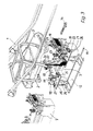
- FIG. 3 shows how the body 3 is continuously moved in the direction of the arrow 14 on the overhead conveyor 1 by means of a body hanger 2.
- the trestles 7 move in the same direction on the oval belt 8 underneath the body hangers 2.
- the chassis units are held in a defined installation position on the mounting plates 15.
- FIG. 3 shows, there is a body 7 with the chassis units placed underneath the body 3, which is lowered from a high transport level 5 to the lower assembly level 6.
- a tool stand 12 is assigned to the body 7 already assigned to the body 3 on both sides of the assembly line in the region of the joining zone 10. (FIGS. 3 to 7 each show the tool frame 12 only on the side facing the viewer.)
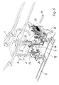
- a driving pin 20 which can be extended in the direction of the body frame 2 and which moves in the direction of the arrow in the movement of the body frame 2 14 engages with the body hanger 2 and thus forcibly takes the tool stand 12 and roughly aligns it with the body 3.
- the mounting plates 15 of the mounting blocks 7 are aligned according to the position of the body 3 via alignment elements 21, which can be acted upon hydraulically, electrically or pneumatically (FIG. 4).
- the body 3 lowers further in the direction of the trestle 7.
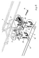
- the body 3 has also approached the assembly level 6 and is now moving on to this level 6.
- the mounting block 7 and the tool blocks 12 are always carried in the same direction.
- parts of units such as, for. B. the struts 23 of the front axle 17 and the shock absorber 24 of the rear axle 18, of holding tools 25 in an optimal position for insertion into the body 3.
- holding tools 25 are arranged on the tool stands 12, which are equipped with mechanical gripping means and can grip and position the parts assigned to them.
- the mounting blocks 7 and the tool blocks 12 are each equipped with hydraulically or mechanically extendable base frames 26.
- the chassis assemblies lying on the support frames 7, centered with respect to the body 3 and held by the holding tools 25 located on the tool supports 12, are lifted up to the body 3 and inserted into their assembly openings on the body 3.
- the base frame 26 of the tool stand 12 can be lowered.
- the assemblies are held in position by the assembly stand 7, the tool stand 12 being able to move back on the guide track 11 (arrow 27 - FIG. 7).
- the units are fastened to the body 3 within the assembly line 4 with the aid of screws. As a result, the driving bolts 20 are retracted.
- the mounting bracket 7 also lowers by retracting its basic frames 26 (FIG. 8). The trestle 7 can pivot out of the assembly line 4 onto the feedback loop 9. There it will be equipped with chassis units for a next assembly process.
Landscapes
- Engineering & Computer Science (AREA)
- Manufacturing & Machinery (AREA)
- Chemical & Material Sciences (AREA)
- Combustion & Propulsion (AREA)
- Transportation (AREA)
- Mechanical Engineering (AREA)
- Automatic Assembly (AREA)
- Automobile Manufacture Line, Endless Track Vehicle, Trailer (AREA)
Applications Claiming Priority (2)
| Application Number | Priority Date | Filing Date | Title |
|---|---|---|---|
| DE19523294A DE19523294A1 (de) | 1995-06-27 | 1995-06-27 | Anlage zum Fügen der Chassis-Aggregate mit der Karosserie eines Kraftfahrzeuges |
| DE19523294 | 1995-06-27 |
Publications (2)
| Publication Number | Publication Date |
|---|---|
| EP0751061A1 true EP0751061A1 (fr) | 1997-01-02 |
| EP0751061B1 EP0751061B1 (fr) | 1997-11-12 |
Family
ID=7765349
Family Applications (1)
| Application Number | Title | Priority Date | Filing Date |
|---|---|---|---|
| EP96109585A Expired - Lifetime EP0751061B1 (fr) | 1995-06-27 | 1996-06-14 | Dispositif pour assembler les sous-ensembles mécaniques avec la carrosserie d'un véhicule à moteur |
Country Status (4)
| Country | Link |
|---|---|
| EP (1) | EP0751061B1 (fr) |
| BR (1) | BR9602883A (fr) |
| DE (2) | DE19523294A1 (fr) |
| ES (1) | ES2113762T3 (fr) |
Cited By (10)
| Publication number | Priority date | Publication date | Assignee | Title |
|---|---|---|---|---|
| EP0945331A3 (fr) * | 1998-03-27 | 1999-12-15 | Adam Opel Ag | Insatallation pour le montage de parts de chassis dans une carrosserie de véhicule |
| WO2008012004A1 (fr) * | 2006-07-28 | 2008-01-31 | Gm Global Technology Operations, Inc. | Dispositif de positionnement de jambe de force |
| WO2010038629A1 (fr) * | 2008-10-02 | 2010-04-08 | Honda Motor Co., Ltd. | Appareil de support pour assemblage de composants de transmission et procédé d’assemblage de véhicule |
| ITTO20091054A1 (it) * | 2009-12-30 | 2011-06-30 | Comau Spa | "installazione per l'assemblaggio di parti meccaniche su scocche di autoveicoli" |
| CN102730101A (zh) * | 2012-06-19 | 2012-10-17 | 奇瑞汽车股份有限公司 | 承载式车身和非承载式车身共线装配生产线及其装配工艺 |
| GB2492264A (en) * | 2008-05-23 | 2012-12-26 | Honda Motor Co Ltd | System and method for synchronously conveying underbody components for vehicle body |
| ITTO20120241A1 (it) * | 2012-03-19 | 2013-09-20 | Cpm S P A | Impianto per assemblare parti meccaniche su scocche di veicoli |
| EP3170722A1 (fr) * | 2015-11-21 | 2017-05-24 | MAN Truck & Bus AG | Procédé et dispositif de montage d'un véhicule, en particulier un véhicule utilitaire |
| CN113263309A (zh) * | 2021-06-11 | 2021-08-17 | 浙江久科智能装备股份有限公司 | 可用于多车型智能转运的底盘装配ems线及其控制方法 |
| CN113692375A (zh) * | 2019-03-26 | 2021-11-23 | 标致雪铁龙汽车股份有限公司 | 车辆装配组件 |
Families Citing this family (7)
| Publication number | Priority date | Publication date | Assignee | Title |
|---|---|---|---|---|
| DE19713860A1 (de) * | 1997-04-04 | 1998-10-08 | Kuka Schweissanlagen Gmbh | Verfahren und Vorrichtung zum Fertigen von komplexen Werkstücken |
| DE10032086A1 (de) * | 2000-07-01 | 2002-01-10 | Volkswagen Ag | Anlage zum Zusammenfügen von Bauteilen |
| DE10342176B4 (de) * | 2003-09-12 | 2017-01-26 | GM Global Technology Operations LLC (n. d. Ges. d. Staates Delaware) | Vollautomatische Montagestation, Schraubeinrichtung und vollautomatisches Montageverfahren mit integrierter Qualitätskontrolle |
| DE102008010394A1 (de) | 2008-02-21 | 2009-08-27 | GM Global Technology Operations, Inc., Detroit | Anlage zum Fügen von Chassisaggregaten mit der Karosserie eines Kraftfahrzeugs und Verfahren zum Fügen von Chassisaggregaten |
| DE102010051789A1 (de) * | 2010-11-18 | 2012-05-24 | GM Global Technology Operations LLC | Fertigungsring mit einem Aufrüststrang und einem Hochzeitsstrang |
| DE102012023765A1 (de) | 2012-12-05 | 2014-06-05 | GM Global Technology Operations LLC (n. d. Ges. d. Staates Delaware) | Karosseriehaltevorrichtung zum Halten einer Fahrzeugkarosserie auf einem Fahrzeugchassis und Montageverfahren |
| CN105197127B (zh) * | 2015-10-14 | 2017-10-27 | 迈赫机器人自动化股份有限公司 | 一种不同车体的半共线及其利用该线体装配车身的工艺 |
Citations (5)
| Publication number | Priority date | Publication date | Assignee | Title |
|---|---|---|---|---|
| EP0226212A2 (fr) * | 1985-12-20 | 1987-06-24 | Bayerische Motoren Werke Aktiengesellschaft, Patentabteilung AJ-3 | Dispositif et procédé pour le montage par en dessous des groupes de propulsion dans une carrosserie automobile |
| US4734979A (en) * | 1985-12-25 | 1988-04-05 | Mazda Motor Corporation | Weighty object mounting systems |
| DE3729084A1 (de) * | 1987-09-01 | 1989-03-16 | Opel Adam Ag | Verfahren zur verbindung von chassis und karosserie von personenkraftwagen und vorrichtung zur durchfuehrung des verfahrens |
| DE4313407A1 (de) * | 1993-04-23 | 1994-10-27 | Kuka Schweissanlagen & Roboter | Verfahren zum automatischen Fügen und Montageanlage |
| EP0629469A1 (fr) | 1992-12-04 | 1994-12-21 | Toyota Jidosha Kabushiki Kaisha | Appareil de montage automatique |
-
1995
- 1995-06-27 DE DE19523294A patent/DE19523294A1/de not_active Withdrawn
-
1996
- 1996-06-14 EP EP96109585A patent/EP0751061B1/fr not_active Expired - Lifetime
- 1996-06-14 ES ES96109585T patent/ES2113762T3/es not_active Expired - Lifetime
- 1996-06-14 DE DE59600046T patent/DE59600046D1/de not_active Expired - Lifetime
- 1996-06-25 BR BR9602883A patent/BR9602883A/pt not_active IP Right Cessation
Patent Citations (5)
| Publication number | Priority date | Publication date | Assignee | Title |
|---|---|---|---|---|
| EP0226212A2 (fr) * | 1985-12-20 | 1987-06-24 | Bayerische Motoren Werke Aktiengesellschaft, Patentabteilung AJ-3 | Dispositif et procédé pour le montage par en dessous des groupes de propulsion dans une carrosserie automobile |
| US4734979A (en) * | 1985-12-25 | 1988-04-05 | Mazda Motor Corporation | Weighty object mounting systems |
| DE3729084A1 (de) * | 1987-09-01 | 1989-03-16 | Opel Adam Ag | Verfahren zur verbindung von chassis und karosserie von personenkraftwagen und vorrichtung zur durchfuehrung des verfahrens |
| EP0629469A1 (fr) | 1992-12-04 | 1994-12-21 | Toyota Jidosha Kabushiki Kaisha | Appareil de montage automatique |
| DE4313407A1 (de) * | 1993-04-23 | 1994-10-27 | Kuka Schweissanlagen & Roboter | Verfahren zum automatischen Fügen und Montageanlage |
Cited By (19)
| Publication number | Priority date | Publication date | Assignee | Title |
|---|---|---|---|---|
| EP0945331A3 (fr) * | 1998-03-27 | 1999-12-15 | Adam Opel Ag | Insatallation pour le montage de parts de chassis dans une carrosserie de véhicule |
| WO2008012004A1 (fr) * | 2006-07-28 | 2008-01-31 | Gm Global Technology Operations, Inc. | Dispositif de positionnement de jambe de force |
| CN101511666B (zh) * | 2006-07-28 | 2012-05-30 | Gm全球科技运作股份有限公司 | 减震支柱定位装置 |
| US8276260B2 (en) | 2006-07-28 | 2012-10-02 | GM Global Technology Operations LLC | Spring strut positioning device |
| US8627942B2 (en) | 2008-05-23 | 2014-01-14 | Honda Motor Co., Ltd. | System and method for synchronously conveying underbody components for vehicle body |
| GB2492264A (en) * | 2008-05-23 | 2012-12-26 | Honda Motor Co Ltd | System and method for synchronously conveying underbody components for vehicle body |
| GB2492264B (en) * | 2008-05-23 | 2013-06-12 | Honda Motor Co Ltd | System and method for synchronously conveying underbody components for vehicle body |
| WO2010038629A1 (fr) * | 2008-10-02 | 2010-04-08 | Honda Motor Co., Ltd. | Appareil de support pour assemblage de composants de transmission et procédé d’assemblage de véhicule |
| CN102239079A (zh) * | 2008-10-02 | 2011-11-09 | 本田技研工业株式会社 | 用于传动系部件组的传送装置和车辆组装方法 |
| ITTO20091054A1 (it) * | 2009-12-30 | 2011-06-30 | Comau Spa | "installazione per l'assemblaggio di parti meccaniche su scocche di autoveicoli" |
| EP2340982A1 (fr) * | 2009-12-30 | 2011-07-06 | COMAU SpA | Installation permettant d'assembler les pièces mécaniques sur les carrosseries de véhicules à moteur |
| WO2013140340A1 (fr) * | 2012-03-19 | 2013-09-26 | Cpm S.P.A. | Usine pour l'assemblage de pièces mécaniques sur des carrosseries de véhicule |
| ITTO20120241A1 (it) * | 2012-03-19 | 2013-09-20 | Cpm S P A | Impianto per assemblare parti meccaniche su scocche di veicoli |
| US9533725B2 (en) | 2012-03-19 | 2017-01-03 | Cpm S.P.A. | Plant for assembling mechanical parts on vehicle bodies |
| CN102730101A (zh) * | 2012-06-19 | 2012-10-17 | 奇瑞汽车股份有限公司 | 承载式车身和非承载式车身共线装配生产线及其装配工艺 |
| CN102730101B (zh) * | 2012-06-19 | 2014-10-01 | 奇瑞汽车股份有限公司 | 承载式车身和非承载式车身共线装配生产线及其装配工艺 |
| EP3170722A1 (fr) * | 2015-11-21 | 2017-05-24 | MAN Truck & Bus AG | Procédé et dispositif de montage d'un véhicule, en particulier un véhicule utilitaire |
| CN113692375A (zh) * | 2019-03-26 | 2021-11-23 | 标致雪铁龙汽车股份有限公司 | 车辆装配组件 |
| CN113263309A (zh) * | 2021-06-11 | 2021-08-17 | 浙江久科智能装备股份有限公司 | 可用于多车型智能转运的底盘装配ems线及其控制方法 |
Also Published As
| Publication number | Publication date |
|---|---|
| BR9602883A (pt) | 1998-04-28 |
| EP0751061B1 (fr) | 1997-11-12 |
| DE19523294A1 (de) | 1997-01-02 |
| ES2113762T3 (es) | 1998-05-01 |
| DE59600046D1 (de) | 1997-12-18 |
Similar Documents
| Publication | Publication Date | Title |
|---|---|---|
| EP0751061B1 (fr) | Dispositif pour assembler les sous-ensembles mécaniques avec la carrosserie d'un véhicule à moteur | |
| EP1075347B1 (fr) | Installation pour positionner et souder des elements de carrosserie de differents types d'automobiles | |
| DE69600603T2 (de) | Vorrichtung zum Aufspannen von Karosserien diverser Typen | |
| DE68907814T2 (de) | Geraet zum schweissen von motorfahrzeugkarosserien. | |
| DE69408644T2 (de) | Vorrichtung zum Punktschweissen von aus Blech bestehenden Strukturen, insbesondere von Mototfahrzeugen | |
| DE4408449A1 (de) | Transportsystem | |
| DE102021106634B3 (de) | Halte- und Positioniervorrichtung für Werkstücke | |
| DE4431384A1 (de) | Vorrichtung zum Umrahmen von Fahrzeugkörpern | |
| DE19902635A1 (de) | Verfahren und Vorrichtung zum Montieren einer Fahrzeugtür | |
| DE69008839T2 (de) | Einrichtung zum Schweissen von aus gepresstem Blech bestehenden Baugruppen von Motorfahrzeugkarosserien. | |
| AT525842A2 (de) | Fertigungslinie | |
| DE102007008480A1 (de) | Bearbeitungslinie | |
| DE7831423U1 (de) | Arbeitsstation für eine Fertigungsstraße, insbesondere für eine Montagemaschine | |
| DE19752685A1 (de) | Maschine zum Bearbeiten von Fensterrahmen-Holmen | |
| EP0226212B1 (fr) | Dispositif et procédé pour le montage par en dessous des groupes de propulsion dans une carrosserie automobile | |
| EP1902815A2 (fr) | Ligne de travail avec une pluralité de dispositifs de transport | |
| DE3712510C2 (fr) | ||
| EP0249946B1 (fr) | Procédé et dispositif pour la fabrication d'un cadre d'espacement pour vitres isolantes | |
| EP0290469B1 (fr) | Dispositif pour l'usinage automatique de pieces ayant des formes differentes | |
| DE69501013T2 (de) | Einrichtung zur Autoverschrottung | |
| EP0134255A1 (fr) | Installation de transport avec des supports déplacés sur des voies de transport | |
| DE3642431C1 (de) | Foerdereinrichtung zum Foerdern von Kraftfahrzeugkarosserien | |
| EP0296151B1 (fr) | Dispositif avec cadre de levage pour l'usinage de pieces | |
| DE202020101753U1 (de) | Wechselvorrichtung für einen Wechsel von wenigstens zwei Werkstückauflagen für eine Bearbeitungsmaschine | |
| DE102019116523B4 (de) | Verfahren zum Wechseln eines Aggregates an einer Verpackungsstraße sowie hierfür ausgelegte Verpackungsstraße |
Legal Events
| Date | Code | Title | Description |
|---|---|---|---|
| PUAI | Public reference made under article 153(3) epc to a published international application that has entered the european phase |
Free format text: ORIGINAL CODE: 0009012 |
|
| AK | Designated contracting states |
Kind code of ref document: A1 Designated state(s): DE ES FR GB IT |
|
| GRAG | Despatch of communication of intention to grant |
Free format text: ORIGINAL CODE: EPIDOS AGRA |
|
| 17P | Request for examination filed |
Effective date: 19970226 |
|
| GRAH | Despatch of communication of intention to grant a patent |
Free format text: ORIGINAL CODE: EPIDOS IGRA |
|
| 17Q | First examination report despatched |
Effective date: 19970421 |
|
| GRAH | Despatch of communication of intention to grant a patent |
Free format text: ORIGINAL CODE: EPIDOS IGRA |
|
| GRAA | (expected) grant |
Free format text: ORIGINAL CODE: 0009210 |
|
| ITF | It: translation for a ep patent filed | ||
| AK | Designated contracting states |
Kind code of ref document: B1 Designated state(s): DE ES FR GB IT |
|
| ET | Fr: translation filed | ||
| GBT | Gb: translation of ep patent filed (gb section 77(6)(a)/1977) |
Effective date: 19971114 |
|
| REF | Corresponds to: |
Ref document number: 59600046 Country of ref document: DE Date of ref document: 19971218 |
|
| REG | Reference to a national code |
Ref country code: ES Ref legal event code: FG2A Ref document number: 2113762 Country of ref document: ES Kind code of ref document: T3 |
|
| PLBE | No opposition filed within time limit |
Free format text: ORIGINAL CODE: 0009261 |
|
| STAA | Information on the status of an ep patent application or granted ep patent |
Free format text: STATUS: NO OPPOSITION FILED WITHIN TIME LIMIT |
|
| 26N | No opposition filed | ||
| REG | Reference to a national code |
Ref country code: GB Ref legal event code: IF02 |
|
| REG | Reference to a national code |
Ref country code: GB Ref legal event code: 732E Free format text: REGISTERED BETWEEN 20090219 AND 20090225 |
|
| REG | Reference to a national code |
Ref country code: GB Ref legal event code: 732E Free format text: REGISTERED BETWEEN 20090305 AND 20090311 |
|
| REG | Reference to a national code |
Ref country code: GB Ref legal event code: 732E Free format text: REGISTERED BETWEEN 20091029 AND 20091104 |
|
| REG | Reference to a national code |
Ref country code: GB Ref legal event code: 732E Free format text: REGISTERED BETWEEN 20091105 AND 20091111 |
|
| REG | Reference to a national code |
Ref country code: DE Ref legal event code: R081 Ref document number: 59600046 Country of ref document: DE Owner name: GM GLOBAL TECHNOLOGY OPERATIONS LLC (N. D. GES, US Free format text: FORMER OWNER: GM GLOBAL TECHNOLOGY OPERATIONS, INC., DETROIT, MICH., US Effective date: 20110323 Ref country code: DE Ref legal event code: R081 Ref document number: 59600046 Country of ref document: DE Owner name: GM GLOBAL TECHNOLOGY OPERATIONS LLC (N. D. GES, US Free format text: FORMER OWNER: GM GLOBAL TECHNOLOGY OPERATIONS, INC., DETROIT, US Effective date: 20110323 |
|
| PG25 | Lapsed in a contracting state [announced via postgrant information from national office to epo] |
Ref country code: IT Free format text: LAPSE BECAUSE OF NON-PAYMENT OF DUE FEES Effective date: 20110614 |
|
| PGFP | Annual fee paid to national office [announced via postgrant information from national office to epo] |
Ref country code: DE Payment date: 20120607 Year of fee payment: 17 |
|
| PGFP | Annual fee paid to national office [announced via postgrant information from national office to epo] |
Ref country code: FR Payment date: 20120619 Year of fee payment: 17 Ref country code: GB Payment date: 20120613 Year of fee payment: 17 |
|
| PGRI | Patent reinstated in contracting state [announced from national office to epo] |
Ref country code: IT Effective date: 20120920 |
|
| PGFP | Annual fee paid to national office [announced via postgrant information from national office to epo] |
Ref country code: IT Payment date: 20120616 Year of fee payment: 17 Ref country code: ES Payment date: 20120726 Year of fee payment: 17 |
|
| GBPC | Gb: european patent ceased through non-payment of renewal fee |
Effective date: 20130614 |
|
| REG | Reference to a national code |
Ref country code: DE Ref legal event code: R119 Ref document number: 59600046 Country of ref document: DE Effective date: 20140101 |
|
| REG | Reference to a national code |
Ref country code: FR Ref legal event code: ST Effective date: 20140228 |
|
| PG25 | Lapsed in a contracting state [announced via postgrant information from national office to epo] |
Ref country code: DE Free format text: LAPSE BECAUSE OF NON-PAYMENT OF DUE FEES Effective date: 20140101 Ref country code: GB Free format text: LAPSE BECAUSE OF NON-PAYMENT OF DUE FEES Effective date: 20130614 |
|
| PG25 | Lapsed in a contracting state [announced via postgrant information from national office to epo] |
Ref country code: FR Free format text: LAPSE BECAUSE OF NON-PAYMENT OF DUE FEES Effective date: 20130701 Ref country code: IT Free format text: LAPSE BECAUSE OF NON-PAYMENT OF DUE FEES Effective date: 20130614 |
|
| REG | Reference to a national code |
Ref country code: ES Ref legal event code: FD2A Effective date: 20140708 |
|
| PG25 | Lapsed in a contracting state [announced via postgrant information from national office to epo] |
Ref country code: ES Free format text: LAPSE BECAUSE OF NON-PAYMENT OF DUE FEES Effective date: 20130615 |