EP0226212A2 - Dispositif et procédé pour le montage par en dessous des groupes de propulsion dans une carrosserie automobile - Google Patents
Dispositif et procédé pour le montage par en dessous des groupes de propulsion dans une carrosserie automobile Download PDFInfo
- Publication number
- EP0226212A2 EP0226212A2 EP86117574A EP86117574A EP0226212A2 EP 0226212 A2 EP0226212 A2 EP 0226212A2 EP 86117574 A EP86117574 A EP 86117574A EP 86117574 A EP86117574 A EP 86117574A EP 0226212 A2 EP0226212 A2 EP 0226212A2
- Authority
- EP
- European Patent Office
- Prior art keywords
- assembly
- units
- hanger
- joining
- clamping
- Prior art date
- Legal status (The legal status is an assumption and is not a legal conclusion. Google has not performed a legal analysis and makes no representation as to the accuracy of the status listed.)
- Granted
Links
Images



Classifications
-
- B—PERFORMING OPERATIONS; TRANSPORTING
- B62—LAND VEHICLES FOR TRAVELLING OTHERWISE THAN ON RAILS
- B62D—MOTOR VEHICLES; TRAILERS
- B62D65/00—Designing, manufacturing, e.g. assembling, facilitating disassembly, or structurally modifying motor vehicles or trailers, not otherwise provided for
- B62D65/02—Joining sub-units or components to, or positioning sub-units or components with respect to, body shell or other sub-units or components
-
- B—PERFORMING OPERATIONS; TRANSPORTING
- B62—LAND VEHICLES FOR TRAVELLING OTHERWISE THAN ON RAILS
- B62D—MOTOR VEHICLES; TRAILERS
- B62D65/00—Designing, manufacturing, e.g. assembling, facilitating disassembly, or structurally modifying motor vehicles or trailers, not otherwise provided for
- B62D65/02—Joining sub-units or components to, or positioning sub-units or components with respect to, body shell or other sub-units or components
- B62D65/10—Joining sub-units or components to, or positioning sub-units or components with respect to, body shell or other sub-units or components the sub-units or components being engines, clutches or transmissions
Definitions
- the invention relates to a method of the type mentioned in the preamble of the first claim and to an apparatus for performing this method according to the preamble of claim 6.
- Such a system is known from DE-OS 33 37 160.
- the assemblies to be assembled are positioned on an assembly assembly carrier. This is moved from station to station by a floor conveyor.
- the bodies which are arranged in a hanger, are placed on the assembly subframe at a joining station.
- reference devices are provided. After the body is placed on the assembly unit carrier, it is moved on to a screwing station, where the screwing robots embedded in the floor and which are movably mounted then screw the units onto the body.
- the bodies completed in this way are then unloaded again from the assembly subframe and transferred to another conveyor system.
- the body is first placed on the assembly subframe and then subsequently removed from it.
- the positioning required when the body is placed on the assembly subframe is addressed, but only one solution in the form is conceivable, that the positioning device also serve as a support device for the body, since the positioning devices are movably mounted in the assembly cross-member.
- the object of the present invention is to provide a method and an apparatus for carrying out the method, with which the connection of the body and units can be carried out much more easily, quickly and reliably.
- the solution is based on the knowledge that the body does not have to be removed from the overhead conveyor to complete it with the units, but that the units are moved to the body from below using a lifting device and then either screwed on immediately or only with the help of assembly -Assembly carrier to be attached to the hanger.
- the joining aid required due to the positional tolerances of the body and the assemblies is arranged in a stationary manner according to the invention and not, as in the prior art, on every assembly assembly carrier. This significantly simplifies the construction of the assembly unit carriers. This also has the advantage that the joining aid has a fixed reference position and that the relatively heavy body does not have to be aligned, but rather that the individual units are aligned after the body.
- a suitable overhead conveyor is described, for example, in DE-OS 35 41 191.
- the assembly subframe is then coupled to the overhead conveyor.
- the screw connection can then be carried out in a separate screwing station. This increases the accessibility of the individual fastening points (claim 2).
- joining aid describe in their mode of operation the characterizing features of claim 4.
- This joining aid is characterized in particular by the fact that no optical monitoring elements or buttons are necessary.
- a device suitable for carrying out the method according to the invention describes the characterizing features of claim 6.
- the development according to claim 7 describes a simple way to allow alignment of the units on the assembly subframe.
- the aggregates can be pre-assembled on the aggregate traverse at workplaces optimized for this. It is also possible to have the aggregate crossbar attached automatically.
- claims 8 and 9 each describe a simply constructed clamping device for clamping the mounting plate in the position corresponding to the body position.
- a cylinder-piston unit which is controlled hydraulically or pneumatically can be used as the control device.
- the features of claim 10 describe a joining aid.
- the advantage of this embodiment is that it takes up little space and can be attached directly next to the transport device for the assembly subframe and the body.
- Another advantage of this joining aid is that both the position detection of the body and the alignment of the units can be carried out by it.
- Claim 14 describes an advantageously constructed correction device for aligning the units according to the position of the body.
- Claim 18 describes a simply constructed, yet functionally reliable fastening device in order to fasten the assembly subassembly to the hanger.
- the development according to claim 19 has the advantage that unintentional opening of the fastening device is prevented.
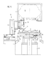
- a overhead conveyor 1 is shown schematically, which is attached to the ceiling or suitable supports of the workshop, not shown. It consists in a manner known per se from the guide rails 2 and the hanger 3 guided and moved therein.
- the hanger 3 carries a body 5 with the interposition of a longitudinal cross member 4.
- the connection between the hanger 3 and the longitudinal cross member 4 and the longitudinal cross member 4 is free of play. Since the fastenings have defined receiving points at the same time, each body 5 is positioned in the overhead conveyor 1.
- a mounting assembly carrier (MAT) 7 guided in a transport device 6 runs.
- This MAT has the shape of a bone and serves to accommodate the front axle, the engine, the transmission, the drive train and the rear axle .
- These aggregates 8 are attached to the MAT 7 with the interposition of aggregate traverses 9.
- a mounting plate 10 is used, which can be moved on rollers in the plane of the MAT.
- the two aggregate traverses themselves are immovably connected to the two mounting plates 10.
- the aggregates 8 are held precisely in the aggregate traverses 9 in predetermined positions. Likewise, the connection between the aggregate traverse 9 and the mounting plates is clearly defined.
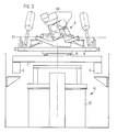
- a MAT 7 is run in on the transport device 6. It carries the mounting plate 10, on which in turn the unit cross-member 9 with the units 8, here a front axle with a motor, is fastened.
- a lifting station 11 is shown below the MAT 7.
- a suitable lifting device 22 is installed in it to raise the entire MAT 7.
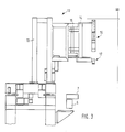
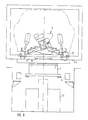
- the joining aid 12 is shown in FIG. 3. It is arranged laterally next to the transport device 6 in such a way that it can be moved from a rest position outside the path of movement of the MAT 7 and the body 5 into the space between the two.
- Four joining aids 12 are provided in each joining station, two for the front axle and two for the rear axle.
- the frame 3 consists of a frame 13 and a frame 14.
- the frame 14 is pivotally mounted on the frame 13 at 15.
- the frame 14 carries the search device 16 at its front upper free end.
- the correction device 17 is attached to its opposite lower free end. The structure and function of the search device 16 and the correction device 17 are described below.
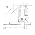
- FIG. 4 shows a side view of the joining aid 12.
- the frame 13 is additionally arranged to be movable in order to move the frame 14 to additional positions of units to the body 5.
- the clamping device 18 is shown in order to clamp the frame 14.
- the clamping device 18 is designed as pliers 19 which are actuated via a control device 20.
- a clamping plate 21 is provided which is connected to the frame 14 and is designed such that it always moves between the two halves of the pliers in the search area of the search device 16.
- positioning of the MAT 7 is achieved in that when it is raised, a conical centering pin engages from the lifting device 22 in an opening provided on the MAT 7. This can also be omitted if the transport device of the MAT 7 can stop it in the joining station in a precisely positioned position.
- the body 5 is then positioned over the hanger 3. This is done by the fact that locking arms, not shown, engage laterally on the hanger 3 (or the longitudinal cross member 4) and clamp it. The clamping takes place in such a way that the hanger 3 is raised slightly by a defined amount, so that the tolerances in the overhead conveyor are always balanced.
- the joining aid 12 is then pivoted into the space between the body 5 and the units 8.
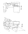
- the search device 16 consists - as shown in FIGS. 6a, b - of a control device designed as a cylinder-piston unit 23.
- the cylinder is attached to the frame 14 and the piston with the piston rod is movably guided in the cylinder.
- the piston rod has either a funnel-shaped opening 24 (FIG. 6a) or a conical head (24.1).
- the axle holder is attached to the body 5. It serves as a search pin 25. This is dimensioned such that it can be received by the funnel-shaped opening 24. Due to the funnel-shaped opening 24 and the fact that the body is clamped in the hanger on the one hand and the hanger on the other hand, only slight deviations in the position of the search pin 25 occur. Now the frame 14 with the search device 16 pivoted under the body 5 and then move up the cylinder-piston unit 23, the funnel-shaped opening 24 and the locating pin 25 will align the cylinder-piston unit 23 and thus the frame 14. Thus, the frame 14 has now grasped the exact position of the body 5. The control device 20 is then actuated. As a result, the two pliers halves 19 move together and clamp the frame 14 in its current position via the clamping plate 21.
- the cylinder-piston unit 23 moves with its conical head 24.1 into the fitting bore 25.1. This also aligns the frame 14. Then he is - as described - fixed.
- the correction device 17 at the lower end of the frame 14 has a pincer-like clamping device 26, which is actuated by a control device 27 via suitable articulated members, FIG. 7b.
- the pliers-like clamping device 26 has centering cuts 26.1 in its jaw area.
- the pincer-like clamping device 26 is actuated by the control device 27 in the closing direction.
- a reference device 28 present on the units, here a bushing, or a unit assembly itself or a mounting plate 10 is then detected and clamped in a precisely defined position due to the formation of the centering cuts 26.1. Since the units 8 are supported in the MAT 7 via the floating mounting plate 10, the units can be moved by the closing movement of the pincer-like clamping device 26.
- levers 29 mounted on the lifting device 22 are provided, one free end of which is provided with a control device 30 and the other free end of which is provided with a stop surface 31.
- the levers 29 are pivoted and slightly raise the mounting plates 10 via the stop surfaces 31 and press them against fixed stops 38 on the MAT 7.
- the mounting plates 10 no longer rest in their floating position, but are rather finely positioned.
- the joining aid 12 is pivoted back by first moving the cylinder-piston unit 23 back and opening the pliers-like clamping device 26.
- the MAT 7 is raised via the lifting device 22 and the units are moved under the body 5 (FIG. 8). Due to the alignment described above, the fastening openings or bolts in the body are now aligned with the fastening openings on the units, so that the screw connection can now take place.
- the MAT 7 is coupled to the hanger 3 via the longitudinal cross member 4.
- the fastening device 32 shown in FIGS. 9a, b is provided on the MAT 7 between the two mounting plates for the front and rear axles.
- This consists of two hinged hooks 33, which can be opened and closed by a control device 35 via a linkage 34. These hooks are designed such that they reach behind the bundles arranged on the longitudinal cross member 4 and thus attach the MAT 7 to the hanger 3 in a hanging manner.
- the control device 35 is operated either automatically or by hand.
- a spring-loaded locking pin 37 is provided, which must first be released in order to pivot the control device 35 into the open position of the hooks 33 (FIG. 9b).
- the body 5 moves to one in the overhead conveyor 1 Screwing station.
- the units 8 can now be screwed to the body 5 by hand by workers or automatically using screwing robots.
- the MAT 7 is decoupled from the hanger 3 by hand or automatically and placed by a lowering device on a transport system, for example an underground conveyor system, so that it can be returned to the loading station for loading and positioning the units.
- a transport system for example an underground conveyor system
- the body 5 is transported by the overhead conveyor 1 to the next processing stations.
Landscapes
- Engineering & Computer Science (AREA)
- Manufacturing & Machinery (AREA)
- Chemical & Material Sciences (AREA)
- Combustion & Propulsion (AREA)
- Transportation (AREA)
- Mechanical Engineering (AREA)
- Automobile Manufacture Line, Endless Track Vehicle, Trailer (AREA)
- Automatic Assembly (AREA)
Applications Claiming Priority (2)
| Application Number | Priority Date | Filing Date | Title |
|---|---|---|---|
| DE3545449 | 1985-12-20 | ||
| DE19853545449 DE3545449A1 (de) | 1985-12-20 | 1985-12-20 | Vorrichtung und verfahren zum zusammenfuegen von aggregaten von der unterseite her an einer kraftfahrzeugkarosse |
Publications (3)
| Publication Number | Publication Date |
|---|---|
| EP0226212A2 true EP0226212A2 (fr) | 1987-06-24 |
| EP0226212A3 EP0226212A3 (en) | 1988-03-23 |
| EP0226212B1 EP0226212B1 (fr) | 1990-01-31 |
Family
ID=6289173
Family Applications (1)
| Application Number | Title | Priority Date | Filing Date |
|---|---|---|---|
| EP86117574A Expired - Lifetime EP0226212B1 (fr) | 1985-12-20 | 1986-12-17 | Dispositif et procédé pour le montage par en dessous des groupes de propulsion dans une carrosserie automobile |
Country Status (3)
| Country | Link |
|---|---|
| EP (1) | EP0226212B1 (fr) |
| DE (2) | DE3545449A1 (fr) |
| ES (1) | ES2012448B3 (fr) |
Cited By (5)
| Publication number | Priority date | Publication date | Assignee | Title |
|---|---|---|---|---|
| EP0311466A1 (fr) * | 1987-10-07 | 1989-04-12 | Automobiles Peugeot | Structure de véhicule automobile à caisse monocoque et son procédé de montage |
| EP0629469A4 (fr) * | 1992-12-04 | 1995-05-24 | Toyota Motor Co Ltd | Appareil de montage automatique. |
| EP0693416A1 (fr) * | 1994-07-22 | 1996-01-24 | Adam Opel Ag | Module d'une automobile et méthode pour son assemblage |
| EP0751061A1 (fr) * | 1995-06-27 | 1997-01-02 | Adam Opel Ag | Dispositif pour assembler les sous-ensembles mécaniques avec la carrosserie d'un véhicule à moteur |
| FR2799428A1 (fr) * | 1999-10-11 | 2001-04-13 | Abb Body In White | Moyen de maintien en position de deux pieces l'une par rapport a l'autre |
Families Citing this family (9)
| Publication number | Priority date | Publication date | Assignee | Title |
|---|---|---|---|---|
| DE3729084C2 (de) * | 1987-09-01 | 1995-05-11 | Opel Adam Ag | Verfahren zur Verbindung von Chassis und Karosserie von Personenkraftwagen und Vorrichtung zur Durchführung des Verfahrens |
| DE3906616A1 (de) * | 1988-03-31 | 1989-10-12 | Kuka Schweissanlagen & Roboter | Montageeinrichtung zum automatischen fuegen von aggregaten von der unterseite her mit einer kfz-karosserie |
| DE58902062D1 (de) * | 1988-03-31 | 1992-09-24 | Kuka Schweissanlagen & Roboter | Montageeinrichtung zum automatischen fuegen von aggregaten von der unterseite her mit einer kfz-karosserie. |
| DE4019796A1 (de) * | 1990-06-21 | 1992-01-02 | Bayerische Motoren Werke Ag | Achse fuer ein kraftfahrzeug |
| DE4025661A1 (de) * | 1990-08-14 | 1992-02-20 | Bayerische Motoren Werke Ag | Vorrichtung zur mittelbaren halterung eines an strukturteilen montierbaren aggregates, insbesondere eines kuehlermoduls am aufbau von kraftfahrzeugen |
| DE19738514A1 (de) * | 1997-09-03 | 1999-03-11 | Daimler Benz Ag | Montagevorrichtung für das Ein- und Ausbauen einer Kraftfahrzeugachse |
| DE102007056849A1 (de) | 2007-11-26 | 2009-05-28 | GM Global Technology Operations, Inc., Detroit | Verfahren zur Montage von Aggregaten an einer Fahrzeugkarosserie und Verwendung eines Mehrfachschrauben-Eindrehwerkzeugs |
| CN106114683B (zh) * | 2016-06-17 | 2018-07-06 | 浙江吉利控股集团有限公司 | 汽车动力总成装配装置及控制方法 |
| DE102017201725B4 (de) | 2017-02-03 | 2023-06-01 | Bayerische Motoren Werke Aktiengesellschaft | Mechanisch gesteuerte Verriegelungsvorrichtung für die Positionssicherung bei der Fahrzeugmontage |
Family Cites Families (4)
| Publication number | Priority date | Publication date | Assignee | Title |
|---|---|---|---|---|
| SE395127B (sv) * | 1974-03-22 | 1977-08-01 | Volvo Ab | Anordning for montering av chassidetaljer pa en bilkaross |
| DE3150476A1 (de) * | 1981-12-19 | 1983-06-30 | Volkswagenwerk Ag, 3180 Wolfsburg | "montageeinrichtung zum zusammenbau von zumindest zwei montageteilen, insbesondere einer fahrzeugkarosse und einem fahrzeugmotor" |
| IT1158820B (it) * | 1983-03-04 | 1987-02-25 | Comau Spa | Sistema programmabile per l'assemblaggio mediante avvitatura delle varie parti meccaniche i autoveicoli alle rispettive scocche |
| JPS608171A (ja) * | 1983-06-24 | 1985-01-17 | Toyota Auto Body Co Ltd | 搬送設備 |
-
1985
- 1985-12-20 DE DE19853545449 patent/DE3545449A1/de not_active Withdrawn
-
1986
- 1986-12-17 ES ES86117574T patent/ES2012448B3/es not_active Expired - Lifetime
- 1986-12-17 DE DE8686117574T patent/DE3668593D1/de not_active Expired - Lifetime
- 1986-12-17 EP EP86117574A patent/EP0226212B1/fr not_active Expired - Lifetime
Cited By (9)
| Publication number | Priority date | Publication date | Assignee | Title |
|---|---|---|---|---|
| EP0311466A1 (fr) * | 1987-10-07 | 1989-04-12 | Automobiles Peugeot | Structure de véhicule automobile à caisse monocoque et son procédé de montage |
| FR2621550A1 (fr) * | 1987-10-07 | 1989-04-14 | Peugeot | Structure de vehicule automobile a caisse monocoque et son procede de montage |
| EP0629469A4 (fr) * | 1992-12-04 | 1995-05-24 | Toyota Motor Co Ltd | Appareil de montage automatique. |
| US5513428A (en) * | 1992-12-04 | 1996-05-07 | Toyota Jidosha Kabushiki Kaisha | Automatic assembling apparatus |
| EP0693416A1 (fr) * | 1994-07-22 | 1996-01-24 | Adam Opel Ag | Module d'une automobile et méthode pour son assemblage |
| EP0751061A1 (fr) * | 1995-06-27 | 1997-01-02 | Adam Opel Ag | Dispositif pour assembler les sous-ensembles mécaniques avec la carrosserie d'un véhicule à moteur |
| FR2799428A1 (fr) * | 1999-10-11 | 2001-04-13 | Abb Body In White | Moyen de maintien en position de deux pieces l'une par rapport a l'autre |
| WO2001026953A1 (fr) * | 1999-10-11 | 2001-04-19 | Abb Body In White | Moyen de maintien en position de deux pieces l'une par rapport a l'autre. |
| US6851166B1 (en) | 1999-10-11 | 2005-02-08 | Abb Body In White | Means for holding two pieces in position in relation to each other |
Also Published As
| Publication number | Publication date |
|---|---|
| ES2012448B3 (es) | 1990-04-01 |
| EP0226212A3 (en) | 1988-03-23 |
| EP0226212B1 (fr) | 1990-01-31 |
| DE3545449A1 (de) | 1987-06-25 |
| DE3668593D1 (de) | 1990-03-08 |
Similar Documents
| Publication | Publication Date | Title |
|---|---|---|
| DE69600603T2 (de) | Vorrichtung zum Aufspannen von Karosserien diverser Typen | |
| DE69822785T2 (de) | Rohrbiegemaschine | |
| DE3121485C2 (de) | Vorrichtung zum Auswechseln von Schweißeinrichtungen bei Schweißanlagen | |
| EP0226212B1 (fr) | Dispositif et procédé pour le montage par en dessous des groupes de propulsion dans une carrosserie automobile | |
| DE3511390C2 (fr) | ||
| DE2920767C2 (de) | Punktschweißmaschine | |
| DE3516284A1 (de) | Verfahren und vorrichtung zum montieren von teilen an einem hauptkoerper | |
| DE69907288T2 (de) | Karosseriehandhabungs- und Montagesystem | |
| EP0440955B1 (fr) | Dispositif pour le montage automatique de câbles électriques avec pièces de connexion dans des boîtiers de prise | |
| DE9105490U1 (de) | Bearbeitungsstation für Werkstücke, insbesondere Fahrzeugkarosserien in einer Transferlinie | |
| DE4408449A1 (de) | Transportsystem | |
| DE3810697C2 (de) | Vorrichtung zur Positionierung eines Anbauteils an einer Karosserie | |
| DE3607020A1 (de) | Montageeinrichtung fuer karosserieteile von kraftfahrzeugen | |
| DE4201289C2 (de) | Vorrichtung zur Handhabung von Werkstücken | |
| DE60318604T2 (de) | Verfahren zur montage einer kraftfahrzeugkarosserie | |
| AT525842A2 (de) | Fertigungslinie | |
| DE3325693C2 (de) | Vorrichtung zum Be- und Entladen einer Vulkanisierpresse für Kraftfahrzeugreifen | |
| EP0290469B1 (fr) | Dispositif pour l'usinage automatique de pieces ayant des formes differentes | |
| DE4219920C2 (de) | Formmaschine und automatisches Formwechselverfahren für eine Formmaschine | |
| DE19918272A1 (de) | Verfahren und Einrichtung zum Bewegen eines Industrieroboters entlang einer Fahrachse | |
| DE3642431C1 (de) | Foerdereinrichtung zum Foerdern von Kraftfahrzeugkarosserien | |
| AT391827B (de) | Handhabungseinrichtung fuer montageteile | |
| WO2021239185A1 (fr) | Système de porte-pièce | |
| EP3858532A1 (fr) | Dispositif d'alimentation en élément pour un appareil de placement et de soudage, un réseau d'élément et ensemble de mise à niveau pour le dispositif de placement et de soudage et procédé d'alimentation correspondant d'une pièce d'assemblage auxiliaire par soudage | |
| AT503648B1 (de) | Bearbeitungsstation |
Legal Events
| Date | Code | Title | Description |
|---|---|---|---|
| PUAI | Public reference made under article 153(3) epc to a published international application that has entered the european phase |
Free format text: ORIGINAL CODE: 0009012 |
|
| AK | Designated contracting states |
Kind code of ref document: A2 Designated state(s): DE ES FR GB IT SE |
|
| PUAL | Search report despatched |
Free format text: ORIGINAL CODE: 0009013 |
|
| AK | Designated contracting states |
Kind code of ref document: A3 Designated state(s): DE ES FR GB IT SE |
|
| 17P | Request for examination filed |
Effective date: 19880211 |
|
| 17Q | First examination report despatched |
Effective date: 19881222 |
|
| GRAA | (expected) grant |
Free format text: ORIGINAL CODE: 0009210 |
|
| AK | Designated contracting states |
Kind code of ref document: B1 Designated state(s): DE ES FR GB IT SE |
|
| GBT | Gb: translation of ep patent filed (gb section 77(6)(a)/1977) | ||
| REF | Corresponds to: |
Ref document number: 3668593 Country of ref document: DE Date of ref document: 19900308 |
|
| ET | Fr: translation filed | ||
| ITF | It: translation for a ep patent filed | ||
| PLBI | Opposition filed |
Free format text: ORIGINAL CODE: 0009260 |
|
| 26 | Opposition filed |
Opponent name: ADAM OPEL AKTIENGESELLSCHAFT Effective date: 19901031 |
|
| ITTA | It: last paid annual fee | ||
| PLBN | Opposition rejected |
Free format text: ORIGINAL CODE: 0009273 |
|
| STAA | Information on the status of an ep patent application or granted ep patent |
Free format text: STATUS: OPPOSITION REJECTED |
|
| 27O | Opposition rejected |
Effective date: 19920130 |
|
| EAL | Se: european patent in force in sweden |
Ref document number: 86117574.3 |
|
| REG | Reference to a national code |
Ref country code: GB Ref legal event code: IF02 |
|
| PGFP | Annual fee paid to national office [announced via postgrant information from national office to epo] |
Ref country code: SE Payment date: 20021122 Year of fee payment: 17 |
|
| PGFP | Annual fee paid to national office [announced via postgrant information from national office to epo] |
Ref country code: ES Payment date: 20021129 Year of fee payment: 17 |
|
| PGFP | Annual fee paid to national office [announced via postgrant information from national office to epo] |
Ref country code: GB Payment date: 20021212 Year of fee payment: 17 |
|
| PGFP | Annual fee paid to national office [announced via postgrant information from national office to epo] |
Ref country code: FR Payment date: 20021230 Year of fee payment: 17 |
|
| PGFP | Annual fee paid to national office [announced via postgrant information from national office to epo] |
Ref country code: DE Payment date: 20030129 Year of fee payment: 17 |
|
| PG25 | Lapsed in a contracting state [announced via postgrant information from national office to epo] |
Ref country code: GB Free format text: LAPSE BECAUSE OF NON-PAYMENT OF DUE FEES Effective date: 20031217 |
|
| PG25 | Lapsed in a contracting state [announced via postgrant information from national office to epo] |
Ref country code: SE Free format text: LAPSE BECAUSE OF NON-PAYMENT OF DUE FEES Effective date: 20031218 Ref country code: ES Free format text: LAPSE BECAUSE OF NON-PAYMENT OF DUE FEES Effective date: 20031218 |
|
| PG25 | Lapsed in a contracting state [announced via postgrant information from national office to epo] |
Ref country code: DE Free format text: LAPSE BECAUSE OF NON-PAYMENT OF DUE FEES Effective date: 20040701 |
|
| EUG | Se: european patent has lapsed | ||
| GBPC | Gb: european patent ceased through non-payment of renewal fee |
Effective date: 20031217 |
|
| PG25 | Lapsed in a contracting state [announced via postgrant information from national office to epo] |
Ref country code: FR Free format text: LAPSE BECAUSE OF NON-PAYMENT OF DUE FEES Effective date: 20040831 |
|
| REG | Reference to a national code |
Ref country code: FR Ref legal event code: ST |
|
| REG | Reference to a national code |
Ref country code: ES Ref legal event code: FD2A Effective date: 20031218 |
|
| PG25 | Lapsed in a contracting state [announced via postgrant information from national office to epo] |
Ref country code: IT Free format text: LAPSE BECAUSE OF NON-PAYMENT OF DUE FEES;WARNING: LAPSES OF ITALIAN PATENTS WITH EFFECTIVE DATE BEFORE 2007 MAY HAVE OCCURRED AT ANY TIME BEFORE 2007. THE CORRECT EFFECTIVE DATE MAY BE DIFFERENT FROM THE ONE RECORDED. Effective date: 20051217 |