EP0752934B1 - Systeme de suspension pour vehicule - Google Patents
Systeme de suspension pour vehicule Download PDFInfo
- Publication number
- EP0752934B1 EP0752934B1 EP95911444A EP95911444A EP0752934B1 EP 0752934 B1 EP0752934 B1 EP 0752934B1 EP 95911444 A EP95911444 A EP 95911444A EP 95911444 A EP95911444 A EP 95911444A EP 0752934 B1 EP0752934 B1 EP 0752934B1
- Authority
- EP
- European Patent Office
- Prior art keywords
- spring
- suspension system
- leaf spring
- pivotal axis
- offset
- Prior art date
- Legal status (The legal status is an assumption and is not a legal conclusion. Google has not performed a legal analysis and makes no representation as to the accuracy of the status listed.)
- Expired - Lifetime
Links
- 239000000725 suspension Substances 0.000 title claims description 50
- 238000006073 displacement reaction Methods 0.000 claims description 16
- 230000000694 effects Effects 0.000 claims description 14
- 238000011068 loading method Methods 0.000 claims description 14
- 230000007935 neutral effect Effects 0.000 claims description 12
- 238000005452 bending Methods 0.000 claims description 11
- 230000001419 dependent effect Effects 0.000 claims 1
- 230000008859 change Effects 0.000 description 10
- 230000033001 locomotion Effects 0.000 description 5
- 238000009434 installation Methods 0.000 description 4
- 230000004048 modification Effects 0.000 description 4
- 238000012986 modification Methods 0.000 description 4
- 230000002411 adverse Effects 0.000 description 2
- 230000008901 benefit Effects 0.000 description 2
- 239000002131 composite material Substances 0.000 description 2
- 230000007423 decrease Effects 0.000 description 2
- 238000004519 manufacturing process Methods 0.000 description 2
- 230000009467 reduction Effects 0.000 description 2
- 229920002430 Fibre-reinforced plastic Polymers 0.000 description 1
- 230000006978 adaptation Effects 0.000 description 1
- 239000000654 additive Substances 0.000 description 1
- 230000000996 additive effect Effects 0.000 description 1
- 230000009977 dual effect Effects 0.000 description 1
- 230000002349 favourable effect Effects 0.000 description 1
- 239000011151 fibre-reinforced plastic Substances 0.000 description 1
- 239000011152 fibreglass Substances 0.000 description 1
- 238000000034 method Methods 0.000 description 1
- 229920000642 polymer Polymers 0.000 description 1
- 238000010008 shearing Methods 0.000 description 1
- 230000003068 static effect Effects 0.000 description 1
Images


Classifications
-
- B—PERFORMING OPERATIONS; TRANSPORTING
- B60—VEHICLES IN GENERAL
- B60G—VEHICLE SUSPENSION ARRANGEMENTS
- B60G11/00—Resilient suspensions characterised by arrangement, location or kind of springs
- B60G11/02—Resilient suspensions characterised by arrangement, location or kind of springs having leaf springs only
- B60G11/10—Resilient suspensions characterised by arrangement, location or kind of springs having leaf springs only characterised by means specially adapted for attaching the spring to axle or sprung part of the vehicle
- B60G11/12—Links, pins, or bushes
-
- B—PERFORMING OPERATIONS; TRANSPORTING
- B60—VEHICLES IN GENERAL
- B60G—VEHICLE SUSPENSION ARRANGEMENTS
- B60G11/00—Resilient suspensions characterised by arrangement, location or kind of springs
- B60G11/32—Resilient suspensions characterised by arrangement, location or kind of springs having springs of different kinds
- B60G11/34—Resilient suspensions characterised by arrangement, location or kind of springs having springs of different kinds including leaf springs
- B60G11/38—Resilient suspensions characterised by arrangement, location or kind of springs having springs of different kinds including leaf springs and also rubber springs
- B60G11/42—Resilient suspensions characterised by arrangement, location or kind of springs having springs of different kinds including leaf springs and also rubber springs the rubber springs being attached to sprung part of the vehicle
-
- B—PERFORMING OPERATIONS; TRANSPORTING
- B60—VEHICLES IN GENERAL
- B60G—VEHICLE SUSPENSION ARRANGEMENTS
- B60G17/00—Resilient suspensions having means for adjusting the spring or vibration-damper characteristics, for regulating the distance between a supporting surface and a sprung part of vehicle or for locking suspension during use to meet varying vehicular or surface conditions, e.g. due to speed or load
- B60G17/02—Spring characteristics, e.g. mechanical springs and mechanical adjusting means
- B60G17/023—Spring characteristics, e.g. mechanical springs and mechanical adjusting means the mechanical spring being a leaf spring
-
- B—PERFORMING OPERATIONS; TRANSPORTING
- B60—VEHICLES IN GENERAL
- B60G—VEHICLE SUSPENSION ARRANGEMENTS
- B60G21/00—Interconnection systems for two or more resiliently-suspended wheels, e.g. for stabilising a vehicle body with respect to acceleration, deceleration or centrifugal forces
- B60G21/02—Interconnection systems for two or more resiliently-suspended wheels, e.g. for stabilising a vehicle body with respect to acceleration, deceleration or centrifugal forces permanently interconnected
- B60G21/04—Interconnection systems for two or more resiliently-suspended wheels, e.g. for stabilising a vehicle body with respect to acceleration, deceleration or centrifugal forces permanently interconnected mechanically
- B60G21/05—Interconnection systems for two or more resiliently-suspended wheels, e.g. for stabilising a vehicle body with respect to acceleration, deceleration or centrifugal forces permanently interconnected mechanically between wheels on the same axle but on different sides of the vehicle, i.e. the left and right wheel suspensions being interconnected
- B60G21/055—Stabiliser bars
- B60G21/0551—Mounting means therefor
-
- B—PERFORMING OPERATIONS; TRANSPORTING
- B60—VEHICLES IN GENERAL
- B60G—VEHICLE SUSPENSION ARRANGEMENTS
- B60G2202/00—Indexing codes relating to the type of spring, damper or actuator
- B60G2202/10—Type of spring
- B60G2202/11—Leaf spring
- B60G2202/112—Leaf spring longitudinally arranged
-
- B—PERFORMING OPERATIONS; TRANSPORTING
- B60—VEHICLES IN GENERAL
- B60G—VEHICLE SUSPENSION ARRANGEMENTS
- B60G2500/00—Indexing codes relating to the regulated action or device
- B60G2500/20—Spring action or springs
Definitions
- This invention concerns a suspension system for a vehicle, in which a leaf spring is provided to suspend the main body or chassis of the vehicle from a wheel-bearing axle of the vehicle.
- Leaf springs are commonly used in vehicle suspension systems and act to deflect under load changes so as to isolate the main body from vibrations and irregularities occasioned in the course of the vehicle's travel over a surface.
- the leaf spring in an unladen, or partly laden states, assumes a curved shape, the curvature of which increases or decreases under load changes, with concurrent change in the length of the spring end points.
- the vehicle main body is suspended from a vehicle axle through a leaf spring having, at its front end, in the intended direction of normal travel of the vehicle, a spring eye and bush which affords a substantially longitudinally fixed disposition of the axle relative to the body.
- a pivotal shackle for accommodating changes of length of the spring as its curvature changes under varying load conditions, is used.
- forces produced by the angle of the shackle can affect the spring deflection rate in a non-uniform manner at various loads.
- the arrangement is similar to that described above but the shackle is replaced by a cam slider bracket in which an upper element of non-uniform curvature bears upon an upper surface of the spring leaf in frictional contact therewith.
- the spring leaf angle changes, in the locality of the cam slider bracket, the upper surface of the spring leaf bears upon differing zones of the curved element of the bracket, which alters the effective length of the spring leaf.
- This also changes the spring leaf deflection rate in a non-uniform manner at various loads and the friction between the curved element and the spring leaf has an adverse effect on the quality of the ride experienced on the main body of the vehicle.
- a modification, of this known system includes a cam slider bracket also but at the front end of the spring leaf and a separate radius leaf affording positive longitudinal location for the axle.
- One known prior art suspension system as described in GB-A-0,973,027 (NILSSON), comprises a leaf spring having an end thereof connected rigidly to an outer rigid sleeve of a torsion spring which provides a pivotal axis for the sleeve which is offset below the neutral axis in bending of the leaf spring and which extends generally normally to the regular working plane of the leaf spring.
- the outer rigid sleeve has at least a portion which extends radially of the leaf spring.
- FIG. 1 Another known prior art suspension system, as described in FR-A1-2570031 (CRR), comprises a leaf spring made from composite materials such as fibreglass, with two radii of curvature along its length.
- the active, or deflection, section has a larger radius of curvature, whilst the section used for attachment at an end of the leaf, has a small radius of curvature.
- the mounting through which the leaf is attached to an offset pivotal axis is clamped to the leaf spring so as to allow no relative movement therebetween, the clamping portion thereof comprising a radius of curvature such that the small radius of curvature of the leaf spring may be fully accommodated therein.
- deflection of the leaf spring causes the mounting to rotate about the offset pivotal axis. This rotation allows the mounting to accommodate any "take-up" in the system during deflection of the leaf.
- a fibre reinforced plastic leaf spring has a wedge shaped end which is clamped into a force application component.
- This force application component is pivotally mounted on a vehicle through a moulded bearing eye, which is offset to the neutral axis in bending of the leaf spring.
- This arrangement allows for the forces applied to the leaf to be transmitted thereto without any significant bending strain or shearing stress being applied to the composite layer and hence to the fibres which are aligned with the neutral axis of bending of the leaf spring, that is longitudinally thereto.
- a rigid member is connected rigidly to a leaf spring affording a first suspension means and to an axis to which the member is pivotally connected.
- the axis is offset from the neutral axis in bending of the leaf spring and which extends generally normally to the regular working place of the leaf spring.
- the rigid member extends radially of the leaf spring.
- Another spring affords a second suspension means which may act mechanically in series or, alternatively, in parallel with the first suspension means.
- anti-roil means preferably in the form of an anti-roil bar or tube, is provided to act in conjunction with the first and second suspension means in order to give the suspension desired anti-roil characteristics.
- a suspension system for a vehicle comprising a leaf spring ranged to suspend a main body or chassis of a vehicle from a wheel-bearing axle thereof, a rigid member connected rigidly to the leaf spring at or adjacent an end thereof and an axis to which the matter is pivotally connected and which is positioned substantially offset from the neutral axis in bending of the leaf spring and which extends generally normally to the regular working plane of the leaf spring, wherein the rigid member is a radial arm having one end connected rigidly to the leaf spring at or adjacent an end thereof and its other end connected pivotally to the offset axis.
- the invention aims to provide an improved suspension system with mounting for the spring which better accommodates changes in spring length.
- the inventive system combines the advantage of a low fiction of the shackle arrangement but with the simplicity of a smaller number of components and with the ability to vary the deflection rate of the spring under different load conditions, whilst also increasing the load-carrying capacity of the spring at higher loads, all this being achieved with a saving of cost and weight.
- the invention is characterised in that the offset pivotal axis is arranged to take-up any notional displacement thereof arising, in operation, from deflections of the leaf spring outside the defined spring loading and deflection ranges.
- the team "regular working plane of the leaf spring” is used to represent that plane in which the leaf spring is deflected under normal working conditions, namely, one which is generally vertical and extends in the fore-and-aft direction of the vehicle.
- the pivotal axis is preferably in the form of a bush provided either at the rear end or the front end of the leaf spring, or there may be such a bush or other pivotal axis at both ends, thereof.
- the centre of the or each bush affords an axis substantially offset from the neutral bending axis of the leaf opening, whose rest position in relation to the adjacent end of the spring may be selected such that no, or substantially no, actual or notional displacement of the offset axis from its rest position will occur for defections of the spring over defined spring loading and deflection ranges.
- the pivotal axis may be in the form of a bush, although other suitable forms of pivotal axis means may be employed.
- any substantially longitudinally-directed displacement of the bush or other pivotal axis means is mostly compensated by an opposite longitudinally-directed displacement of the bush or other pivotal axis means arising from a change of the local spring angle.
- the bush or other pivotal axis means will experience no, or substantially no, actual displacement; whereas, for defections outside these defined ranges, any notional displacement may be taken up by the bush or other pivotal axis means.
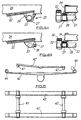
- FIG. 1A of the accompanying drawings there is shown a vehicle axle 1 from which the vehicles main body (not shown) is suspended through a leaf spring 2 having, at its front end, in the intended direction of normal travel of the vehicle, a spring eye 3 and bush 4 which affords a substantially longitudinally fixed disposition of the axle relative to the body.
- a pivotal shackle 5 for accommodating changes of length of the spring 2 as its curvature changes under varying load conditions, is used.
- forces produced by the angle of the shackle 5 can affect the spring deflection rate in a non-uniform manner at various loads.
- FIG. 1B A second prior art suspension system is shown in Figure 1B, wherein the arrangement is similar to that described above in relation to Figure 1A but the shackle 5 is replaced by a cam slider bracket 6 in which an upper element 7 of non-uniform curvature bears upon an upper surface of the spring leaf 2 in frictional contact therewith.
- the spring leaf angle changes, in the locality of the cam slider bracket 6, the upper surface of the spring leaf 2 bears upon differing zones of the curved element 7 of the bracket, which alters the effective length of the spring leaf.
- This also changes the spring leaf deflection rate in a non-uniform manner at various loads and the friction between the curved element 7 and the spring leaf 2 has an adverse effect on the quality of the ride experienced on the main body of the vehicle.
- a modification, of this known system, as shown in Figure 1C, includes a cam slider bracket 8 also but at the front end of the spring leaf 2 and a separate radius 9 leaf affording positive longitudinal location for the axle 1.
- a preferred embodiment of inventive suspension system comprises a leaf spring 12, as shown in Figures 2 and 3A and 3B, which suspends a vehicle chassis or body (not shown) from a wheel-bearing axle (also not shown) of the vehicle.
- the front end of the spring 12, as seen in the intended normal direction of travel of the vehicle, is mounted to the chassis or body through a spring eye 13 and bush 14, as is well known, and by such means the position of the axle, in the longitudinal sense of the vehicle, is substantially fixed.
- the rear end of the spring 12 has rigidly connected to it one end of a rigid radial arm 15 which has its other end connected to a bush 16 which thus lies substantially offset, in this instance below, from the neutral axis in bending of the leaf spring 12 and whose pivotal axis extends generally normally to the regular working plane of the spring.
- the rearward end of the spring 12 is otherwise unrestrained.
- the rearward motion due to the increase in effective length is substantially compensated by a forward motion of an offset pivotal axis 20 due to the lessening of the spring angle.
- a forward motion of an offset pivotal axis 20 due to the lessening of the spring angle.
- a rigid radial arm 15 connects the rearward end of the spring 12 to a bush 16 whose centre point coincides with the required offset axis 20.
- Means associated with the axis 20 mounts the bush 16 to the vehicle body or chassis.
- the design and/or resistance of the bush 16 may be such as to take up the error, or notional displacement, in the offset pivotal axis 20 due to larger spring deflections.
- the bush 20 could have sufficient flexibility of the working range of the spring 12, or could have voids formed therein in the horizontal direction.
- Figure 3A illustrates the situation extant when the suspension is lightly loaded, say when the vehicle is unladen.
- deflection of the spring 12 from the heavily curved "rest" position shown has the effect of producing greater notional displacement of the offset pivotal axis 20 in a rearward sense, arising from an increase in the effective length of the spring 12, than the relatively lesser notional displacement in a forward sense, arising from a lessening of the local spring angle.
- the resultant desired displacement of the offset pivotal axis 20 is resisted by the bush 16 giving rise to a mismatch offset force, towards the centre of the spring 12.
- the torque produced, as shown by arrow A tends to deflect the spring by a greater amount than a free spring under the given load increase, the effect of this being a softening of the spring, which is usually desirable at light load.
- Figure 3B illustrates the situation extant when the suspension is heavily loaded, say when the vehicle is at or above its design load.
- deflection of the spring 12 whose profile is approaching flat in the rest position, has the effect of producing a lesser notional displacement of the offset pivotal axis 20 in a rearward sense, arising from an increase in the effective length of the spring 12, than a relatively greater notional displacement in a forward sense, arising from a lessening of local spring angle.
- the torque B produced resists deflection under an increase in load, the effect of which is to stiffen the spring.
- the stresses within the spring 12 are reduced compared with free spring stresses under the given load. In normal use, this stiffening of the spring 12 and the reduction in stresses are desirable features in a vehicle suspension system when operating at higher loadings.
- the invention broadly conceived is not limited to the details of the embodiment described above. For example, it extends to the provision of a bush not only at the rear end of the spring 12, as already described, but in addition or alternative at the front end of the spring 12. Such a front end bush would also be positioned substantially offset from the neutral axis in bending of the spring by a rigid radial arm connected rigidly at one end of the spring, with the pivotal axis 20 of the bush extending generally normally to the regular working plane of the spring.
- the present invention may advantageously be incorporated in a suspension system utilising an anti-roll device, for example, an anti-roll torsion bar or tube.
- a vehicle suspension system comprises a pair of leaf springs 22 mounted by means of a suitable bracket 25 to an anti-roll bar 23 which extends transversely of the vehicle chassis 24.
- the bracket 25 affords a rigid arm 26 extending radially from the anti-roll bar 25, which is thus offset below the neutral axis of the spring, to an end part of the springs 22.
- a bush 27 Encircling the anti-roll bar 25 at a position, here shown transversely inwardly of the vehicle chassis, is a bush 27 the housing 28 of which is secured to the anti-roll bar 25 or the vehicle chassis 24 to allow rotation of the bar 25 relative to the chassis.
- the suspension system is similar to that shown in Figure 4A but in this instance the housing 38 of the bush 37 does not encircle the anti-roll bar 33. Rather, it is secured to the rear of the anti-roll bar 33, to provide a so-called “resistance arm" which acts between the anti-roll bar 33 and the vehicle chassis or frame 34, during straight axle static bounce of the suspension, to at least partially counteract any consequential rotational movement of the anti-roll bar, thereby applying a couple or moment to, and, as a result altering the deflection and rate of, the suspension.
- the housing 38 of the bush 37 does not encircle the anti-roll bar 33. Rather, it is secured to the rear of the anti-roll bar 33, to provide a so-called “resistance arm" which acts between the anti-roll bar 33 and the vehicle chassis or frame 34, during straight axle static bounce of the suspension, to at least partially counteract any consequential rotational movement of the anti-roll bar, thereby applying a couple or moment to, and, as a result alter
- the high torque effect on the spring creates a high stiffening therefor and an associated reduction in stress in the spring 22, 32.
- These are normally desirable features of a suspension system, allowing the use of a softer, cheaper and higher stressed spring under normal working loadings.
- the present invention may advantageously be incorporated in a suspension system utilising an auxiliary spring as described also in our published International Patent Application No. WO 90/11201.
- the vehicle axle mounts a main leaf spring 142 having the usual spring eye and bush, and shackle, mountings 44, 45, and an auxiliary leaf spring 42' is mounted by both front and rear bushes 47 which, in accordance with the present invention, are offset below the neutral axis of the spring 42'.
- the bushes 47' in this embodiment are constructed with horizontal voids.
- a transverse anti-roll bar could also be incorporated, if desired, in a manner similar to that illustrated in Figure 4A or 4B above.
- the anti-roll bars 43 extend transversely between front and rear ends of the auxiliary leaf springs 42' at respective longitudinal sides of the vehicle.
- the invention provides a convenient, simple, effective and efficient suspension system which avoids the disadvantages of the prior art shackle and cam slider bracket arrangements, whilst additionally giving increased performance arising from automatic adaptation of the system to, respectively, low and high suspension loadings, through the appropriate softening or stiffening effects on the spring.
Landscapes
- Engineering & Computer Science (AREA)
- Mechanical Engineering (AREA)
- Vehicle Body Suspensions (AREA)
Claims (13)
- Système de suspension pour un véhicule, comprenant un ressort à lame (12, 12') conçu pour suspendre un corps principal ou châssis du véhicule à un essieu porteur de roues de celui-ci, un organe rigide (15) relié rigidement au ressort à lame (12, 12') au niveau ou à proximité d'une extrémité de ce dernier et un axe (20) auquel l'organe (15) est relié de manière pivotante, axe (20) qui est positionné de manière sensiblement décalée par rapport à l'axe neutre en flexion du ressort à lame (12, 12') et qui s'étend sensiblement perpendiculairement au plan de travail normal du ressort à lame, l'organe rigide (15) étant un bras radial dont l'une des extrémités est reliée de manière rigide au ressort à lame (12, 12') au niveau ou à proximité d'une extrémité de celui-ci et dont l'autre extrémité est reliée de manière pivotante à l'axe décalé (20), caractérisé en ce que la position de l'axe de pivotement décalé (20) par rapport au ressort à lame (12, 12'), lorsque le système est au repos, est choisie pour qu'en fonctionnement des déformations du ressort à lame (12, 12') sur des plages de charges et de déformations élastiques définies n'engendrent pas ou sensiblement pas de déplacement réel ou fictif de l'axe de pivotement décalé (20) par rapport à la position de repos de celui-ci et pour que l'axe de pivotement décalé (20) soit disposé par rapport au ressort à lame (12, 12') et relié à celui-ci de telle façon que :ces forces résultant de déformations du ressort en dehors des plages de charges et de déformations élastiques définies,(a) dans un état de charge relativement légère du système de suspension, des forces opérationnelles créent un effet d'assouplissement du ressort ; et(b) dans un état de charge relativement importante du système de suspension, des forces opérationnelles créent un effet de raidissement du ressort ;
et en ce que l'axe de pivotement décalé (20) est conçu pour compenser tous ses déplacements fictifs résultant, en fonctionnement, de déformations du ressort à lame (12, 12') en dehors des plages de charges et de déformations élastiques définies. - Système de suspension selon la revendication 1, dans lequel l'axe de pivotement décalé (20) a une flexibilité suffisante pour lui permettre d'absorber ladite compensation.
- Système de suspension selon l'une des revendications précédentes, dans lequel l'axe de pivotement décalé (20) comprend un manchon (16).
- Système de suspension selon la revendication 3 lorsque celle-ci est dépendante de la revendication 1 ou 2, dans lequel le manchon (16) comporte des vides intérieurs pour absorber ladite compensation.
- Système de suspension selon l'une quelconque des revendications précédentes, dans lequel le ressort à lame (12) est monté sur un dispositif antiroulis transversal (23) sur lequel le corps ou châssis (24) du véhicule est monté, l'axe de pivotement décalé étant dans une relation concentrique avec le dispositif antiroulis (23).
- Système de suspension selon la revendication 5, dans lequel le ressort à lame (22) est monté sur un dispositif antiroulis transversal (23) au moyen d'une première patte (25), le montage du corps ou châssis (24) du véhicule sur le dispositif antiroulis (23) étant réalisé au moyen d'une seconde patte comportant une partie (25) logeant l'axe de pivotement décalé dans une relation concentrique avec le dispositif antiroulis (23).
- Système de suspension selon la revendication 6, dans lequel les première et seconde pattes sont combinées pour former un seul ensemble formant patte.
- Système de suspension selon l'une quelconque des revendications 1 à 6, dans lequel le ressort à lame (32) est monté sur un dispositif antiroulis transversal (33) sur lequel le corps ou châssis (34) du véhicule est monté, l'axe de pivotement décalé étant dans une relation non concentrique avec le dispositif antiroulis (33).
- Système de suspension selon la revendication 8, dans lequel le ressort à lame (32) est monté sur le dispositif antiroulis transversal (33) au moyen d'une première patte, le montage du corps ou châssis (34) du véhicule sur le dispositif antiroulis (33) étant réalisé au moyen d'une seconde patte comportant une partie (38) logeant l'axe de pivotement décalé dans une relation non concentrique avec le dispositif antiroulis (33).
- Système de suspension selon l'une quelconque des revendications 5 à 9, dans lequel le dispositif antiroulis (23, 33, 43) est une barre ou un tube de torsion.
- Système de suspension selon l'une quelconque des revendications précédentes, comprenant un organe rigide (15) et un axe de pivotement décalé (20) associé situés au niveau ou à proximité de l'une ou l'autre des extrémités du ressort à lame (12, 12') ou au niveau ou à proximité des deux extrémités de celui-ci.
- Système de suspension selon l'une quelconque des revendications précédentes, dans lequel le ressort à lame (42') est un élément auxiliaire d'un ressort à lame principal (42) de montage d'un essieu porteur de roues du véhicule.
- Véhicule comportant un système de suspension selon l'une quelconque des revendications précédentes.
Applications Claiming Priority (3)
| Application Number | Priority Date | Filing Date | Title |
|---|---|---|---|
| GB9406453 | 1994-03-31 | ||
| GB9406453A GB9406453D0 (en) | 1994-03-31 | 1994-03-31 | Vehicle suspension system |
| PCT/GB1995/000613 WO1995026887A1 (fr) | 1994-03-31 | 1995-03-20 | Systeme de suspension pour vehicule |
Publications (2)
| Publication Number | Publication Date |
|---|---|
| EP0752934A1 EP0752934A1 (fr) | 1997-01-15 |
| EP0752934B1 true EP0752934B1 (fr) | 2000-07-19 |
Family
ID=10752854
Family Applications (1)
| Application Number | Title | Priority Date | Filing Date |
|---|---|---|---|
| EP95911444A Expired - Lifetime EP0752934B1 (fr) | 1994-03-31 | 1995-03-20 | Systeme de suspension pour vehicule |
Country Status (6)
| Country | Link |
|---|---|
| EP (1) | EP0752934B1 (fr) |
| AU (1) | AU1901595A (fr) |
| DE (1) | DE69518068T2 (fr) |
| ES (1) | ES2149352T3 (fr) |
| GB (1) | GB9406453D0 (fr) |
| WO (1) | WO1995026887A1 (fr) |
Cited By (2)
| Publication number | Priority date | Publication date | Assignee | Title |
|---|---|---|---|---|
| CN103085621A (zh) * | 2011-10-17 | 2013-05-08 | 通用汽车环球科技运作有限责任公司 | 用于机动车的车轮悬架系统 |
| EP2885554B1 (fr) | 2013-07-23 | 2016-10-26 | Muhr und Bender KG | Système à ressort à lame pour véhicule automobile |
Families Citing this family (5)
| Publication number | Priority date | Publication date | Assignee | Title |
|---|---|---|---|---|
| US6361026B2 (en) | 1994-03-31 | 2002-03-26 | Detroit Steel Products Co., Inc. | Vehicle suspension system |
| US5938221A (en) * | 1997-12-08 | 1999-08-17 | The Boler Company | Tapered convolute leaf spring for truck suspensions |
| US6129369A (en) | 1998-03-18 | 2000-10-10 | The Boler Company. | Leaf spring distal end portion single rotation point attachment part |
| CN100406285C (zh) * | 2004-02-12 | 2008-07-30 | 吉林大学 | 机械式消扭悬架 |
| GB0420887D0 (en) | 2004-09-20 | 2004-10-20 | Detroit Steel Products Co Inc | Vehicle suspension handling stabilsation system |
Citations (2)
| Publication number | Priority date | Publication date | Assignee | Title |
|---|---|---|---|---|
| FR2570031A1 (fr) * | 1984-09-10 | 1986-03-14 | Rech Ressorts Centre | Dispositif de fixation des extremites de ressorts a lame |
| EP0242548A1 (fr) * | 1986-04-24 | 1987-10-28 | Audi Ag | Dispositif comprenant une lame en matériau fibre-composite et une partie finale transmettant les efforts |
Family Cites Families (8)
| Publication number | Priority date | Publication date | Assignee | Title |
|---|---|---|---|---|
| US1792842A (en) * | 1927-03-17 | 1931-02-17 | Gen Motors Corp | Rubber spring shackle |
| DE583361C (de) * | 1932-05-19 | 1933-09-04 | Hoesch Koeln Neuessen Akt Ges | Tragblattfederabstuetzung, insbesondere fuer Kraftfahrzeuge |
| GB410282A (en) * | 1933-02-10 | 1934-05-17 | Vernon Anthony Trier | Improvements in or relating to pivotal joints |
| CH389423A (de) * | 1960-12-14 | 1965-03-15 | Leander Nilsson August | Fahrzeugfederung |
| US3491994A (en) * | 1967-09-08 | 1970-01-27 | Ford Motor Co | Leaf spring vehicle suspension |
| DE3329686C2 (de) * | 1983-08-17 | 1994-02-17 | Volkswagen Ag | Spurweitenkonstante Achsaufhängung, insbesondere Hinterachsaufhängung, für Kraftfahrzeuge |
| DE3332952A1 (de) * | 1983-09-13 | 1985-03-28 | Jörn, geb. Roth, Frieda, 7012 Fellbach | Elastische lagerung von blattfederenden fuer strassen- und schienenfahrzeuge |
| GB8906600D0 (en) * | 1989-03-22 | 1989-05-04 | Detroit Steel Products Co Inc | Vehicle suspension |
-
1994
- 1994-03-31 GB GB9406453A patent/GB9406453D0/en active Pending
-
1995
- 1995-03-20 WO PCT/GB1995/000613 patent/WO1995026887A1/fr not_active Ceased
- 1995-03-20 ES ES95911444T patent/ES2149352T3/es not_active Expired - Lifetime
- 1995-03-20 DE DE69518068T patent/DE69518068T2/de not_active Expired - Fee Related
- 1995-03-20 AU AU19015/95A patent/AU1901595A/en not_active Abandoned
- 1995-03-20 EP EP95911444A patent/EP0752934B1/fr not_active Expired - Lifetime
Patent Citations (2)
| Publication number | Priority date | Publication date | Assignee | Title |
|---|---|---|---|---|
| FR2570031A1 (fr) * | 1984-09-10 | 1986-03-14 | Rech Ressorts Centre | Dispositif de fixation des extremites de ressorts a lame |
| EP0242548A1 (fr) * | 1986-04-24 | 1987-10-28 | Audi Ag | Dispositif comprenant une lame en matériau fibre-composite et une partie finale transmettant les efforts |
Cited By (5)
| Publication number | Priority date | Publication date | Assignee | Title |
|---|---|---|---|---|
| CN103085621A (zh) * | 2011-10-17 | 2013-05-08 | 通用汽车环球科技运作有限责任公司 | 用于机动车的车轮悬架系统 |
| US8777247B2 (en) | 2011-10-17 | 2014-07-15 | GM Global Technology Operations LLC | Wheel suspension device for a motor vehicle |
| CN103085621B (zh) * | 2011-10-17 | 2016-03-30 | 通用汽车环球科技运作有限责任公司 | 用于机动车的车轮悬架系统 |
| EP2885554B1 (fr) | 2013-07-23 | 2016-10-26 | Muhr und Bender KG | Système à ressort à lame pour véhicule automobile |
| US9868330B2 (en) | 2013-07-23 | 2018-01-16 | Muhr Und Bender Kg | Leaf spring assembly for motor vehicles |
Also Published As
| Publication number | Publication date |
|---|---|
| ES2149352T3 (es) | 2000-11-01 |
| DE69518068D1 (de) | 2000-08-24 |
| DE69518068T2 (de) | 2001-03-22 |
| AU1901595A (en) | 1995-10-23 |
| GB9406453D0 (en) | 1994-05-25 |
| WO1995026887A1 (fr) | 1995-10-12 |
| EP0752934A1 (fr) | 1997-01-15 |
Similar Documents
| Publication | Publication Date | Title |
|---|---|---|
| US4887841A (en) | Vehicle suspension | |
| EP1583672B1 (fr) | Assemblage de fixation | |
| US4650211A (en) | Vehicle rear wheel suspension with dual links extending in the overall forward direction | |
| US4779893A (en) | Strut type vehicle wheel suspension | |
| US4420171A (en) | Heavy vehicle suspension assembly with free floating springs and axle stabilizing torque rod | |
| US5678845A (en) | Stabilizer for a steer axle air ride suspension of a vehicle | |
| KR100319580B1 (ko) | 전방서스펜션 | |
| CA2323214C (fr) | Partie de fixation sur point de rotation unique d'une partie d'extremite distale d'un ressort a lames | |
| US6361026B2 (en) | Vehicle suspension system | |
| WO1990011200A1 (fr) | Systemes de suspension de vehicule | |
| US20090085318A1 (en) | Vehicle leaf spring suspension with radius arms | |
| EP3648993B1 (fr) | Suspension de véhicule | |
| GB2300162A (en) | Rear suspension system for vehicle | |
| EP1185428B1 (fr) | Systeme de stabilisation anti-roulis a suspension pneumatique | |
| EP0587663B1 (fr) | Systeme de suspension pour vehicules | |
| EP0752934A1 (fr) | Systeme de suspension pour vehicule | |
| EP0058950A2 (fr) | Dispositif de suspension de roue indépendante pour véhicule moteur | |
| JP2015123953A (ja) | 車軸のラジアスロッド取付構造 | |
| EP0276218A1 (fr) | Suspension de vehicules | |
| WO2006121438A2 (fr) | Suspension de vehicule a ressorts a lames pourvus de bras longitudinaux | |
| EP0102772B1 (fr) | Suspension pour véhicules | |
| DE102019209977A1 (de) | Achsaufhängung für ein Fahrzeug | |
| CA3068518C (fr) | Suspension de vehicule | |
| KR20240058683A (ko) | 차량용 현가장치 | |
| US6942231B2 (en) | Single passive anti-roll compensator |
Legal Events
| Date | Code | Title | Description |
|---|---|---|---|
| PUAI | Public reference made under article 153(3) epc to a published international application that has entered the european phase |
Free format text: ORIGINAL CODE: 0009012 |
|
| 17P | Request for examination filed |
Effective date: 19960927 |
|
| AK | Designated contracting states |
Kind code of ref document: A1 Designated state(s): DE ES FR GB IT SE |
|
| 17Q | First examination report despatched |
Effective date: 19980714 |
|
| GRAG | Despatch of communication of intention to grant |
Free format text: ORIGINAL CODE: EPIDOS AGRA |
|
| 17Q | First examination report despatched |
Effective date: 19980714 |
|
| GRAG | Despatch of communication of intention to grant |
Free format text: ORIGINAL CODE: EPIDOS AGRA |
|
| GRAH | Despatch of communication of intention to grant a patent |
Free format text: ORIGINAL CODE: EPIDOS IGRA |
|
| GRAH | Despatch of communication of intention to grant a patent |
Free format text: ORIGINAL CODE: EPIDOS IGRA |
|
| GRAA | (expected) grant |
Free format text: ORIGINAL CODE: 0009210 |
|
| AK | Designated contracting states |
Kind code of ref document: B1 Designated state(s): DE ES FR GB IT SE |
|
| ITF | It: translation for a ep patent filed | ||
| REF | Corresponds to: |
Ref document number: 69518068 Country of ref document: DE Date of ref document: 20000824 |
|
| REG | Reference to a national code |
Ref country code: ES Ref legal event code: FG2A Ref document number: 2149352 Country of ref document: ES Kind code of ref document: T3 |
|
| ET | Fr: translation filed | ||
| PLBE | No opposition filed within time limit |
Free format text: ORIGINAL CODE: 0009261 |
|
| STAA | Information on the status of an ep patent application or granted ep patent |
Free format text: STATUS: NO OPPOSITION FILED WITHIN TIME LIMIT |
|
| 26N | No opposition filed | ||
| REG | Reference to a national code |
Ref country code: GB Ref legal event code: IF02 |
|
| PGFP | Annual fee paid to national office [announced via postgrant information from national office to epo] |
Ref country code: GB Payment date: 20060314 Year of fee payment: 12 |
|
| PGFP | Annual fee paid to national office [announced via postgrant information from national office to epo] |
Ref country code: ES Payment date: 20060322 Year of fee payment: 12 |
|
| PGFP | Annual fee paid to national office [announced via postgrant information from national office to epo] |
Ref country code: FR Payment date: 20060327 Year of fee payment: 12 |
|
| PGFP | Annual fee paid to national office [announced via postgrant information from national office to epo] |
Ref country code: DE Payment date: 20060329 Year of fee payment: 12 |
|
| PG25 | Lapsed in a contracting state [announced via postgrant information from national office to epo] |
Ref country code: SE Free format text: LAPSE BECAUSE OF NON-PAYMENT OF DUE FEES Effective date: 20070321 |
|
| EUG | Se: european patent has lapsed | ||
| GBPC | Gb: european patent ceased through non-payment of renewal fee |
Effective date: 20070320 |
|
| REG | Reference to a national code |
Ref country code: FR Ref legal event code: ST Effective date: 20071130 |
|
| PG25 | Lapsed in a contracting state [announced via postgrant information from national office to epo] |
Ref country code: DE Free format text: LAPSE BECAUSE OF NON-PAYMENT OF DUE FEES Effective date: 20071002 |
|
| PGFP | Annual fee paid to national office [announced via postgrant information from national office to epo] |
Ref country code: SE Payment date: 20060321 Year of fee payment: 12 Ref country code: IT Payment date: 20070727 Year of fee payment: 13 |
|
| PG25 | Lapsed in a contracting state [announced via postgrant information from national office to epo] |
Ref country code: GB Free format text: LAPSE BECAUSE OF NON-PAYMENT OF DUE FEES Effective date: 20070320 |
|
| REG | Reference to a national code |
Ref country code: ES Ref legal event code: FD2A Effective date: 20070321 |
|
| PG25 | Lapsed in a contracting state [announced via postgrant information from national office to epo] |
Ref country code: FR Free format text: LAPSE BECAUSE OF NON-PAYMENT OF DUE FEES Effective date: 20070402 Ref country code: ES Free format text: LAPSE BECAUSE OF NON-PAYMENT OF DUE FEES Effective date: 20070321 |
|
| PG25 | Lapsed in a contracting state [announced via postgrant information from national office to epo] |
Ref country code: IT Free format text: LAPSE BECAUSE OF NON-PAYMENT OF DUE FEES Effective date: 20080320 |