EP0753246B1 - Mähmaschine mit einer verbesserter Schwadvorrichtung - Google Patents
Mähmaschine mit einer verbesserter Schwadvorrichtung Download PDFInfo
- Publication number
- EP0753246B1 EP0753246B1 EP96440053A EP96440053A EP0753246B1 EP 0753246 B1 EP0753246 B1 EP 0753246B1 EP 96440053 A EP96440053 A EP 96440053A EP 96440053 A EP96440053 A EP 96440053A EP 0753246 B1 EP0753246 B1 EP 0753246B1
- Authority
- EP
- European Patent Office
- Prior art keywords
- cutting
- windrowing
- cutting mechanism
- mower according
- rotor
- Prior art date
- Legal status (The legal status is an assumption and is not a legal conclusion. Google has not performed a legal analysis and makes no representation as to the accuracy of the status listed.)
- Expired - Lifetime
Links
- 230000007246 mechanism Effects 0.000 claims abstract description 105
- 230000005540 biological transmission Effects 0.000 claims description 26
- 239000000463 material Substances 0.000 claims description 5
- 230000002093 peripheral effect Effects 0.000 claims description 5
- 230000000284 resting effect Effects 0.000 claims description 3
- 239000004459 forage Substances 0.000 description 4
- 230000001012 protector Effects 0.000 description 3
- 238000010009 beating Methods 0.000 description 1
- 230000000903 blocking effect Effects 0.000 description 1
- 230000008878 coupling Effects 0.000 description 1
- 238000010168 coupling process Methods 0.000 description 1
- 238000005859 coupling reaction Methods 0.000 description 1
- 230000001627 detrimental effect Effects 0.000 description 1
- 238000012986 modification Methods 0.000 description 1
- 230000004048 modification Effects 0.000 description 1
- 230000001681 protective effect Effects 0.000 description 1
- 238000006467 substitution reaction Methods 0.000 description 1
Images


Classifications
-
- A—HUMAN NECESSITIES
- A01—AGRICULTURE; FORESTRY; ANIMAL HUSBANDRY; HUNTING; TRAPPING; FISHING
- A01D—HARVESTING; MOWING
- A01D57/00—Delivering mechanisms for harvesters or mowers
- A01D57/30—Rotating attachments for forming windrows
-
- A—HUMAN NECESSITIES
- A01—AGRICULTURE; FORESTRY; ANIMAL HUSBANDRY; HUNTING; TRAPPING; FISHING
- A01D—HARVESTING; MOWING
- A01D34/00—Mowers; Mowing apparatus of harvesters
- A01D34/01—Mowers; Mowing apparatus of harvesters characterised by features relating to the type of cutting apparatus
- A01D34/412—Mowers; Mowing apparatus of harvesters characterised by features relating to the type of cutting apparatus having rotating cutters
- A01D34/63—Mowers; Mowing apparatus of harvesters characterised by features relating to the type of cutting apparatus having rotating cutters having cutters rotating about a vertical axis
- A01D34/64—Mowers; Mowing apparatus of harvesters characterised by features relating to the type of cutting apparatus having rotating cutters having cutters rotating about a vertical axis mounted on a vehicle, e.g. a tractor, or drawn by an animal or a vehicle
- A01D34/66—Mowers; Mowing apparatus of harvesters characterised by features relating to the type of cutting apparatus having rotating cutters having cutters rotating about a vertical axis mounted on a vehicle, e.g. a tractor, or drawn by an animal or a vehicle with two or more cutters
- A01D34/667—Means for directing the cut crop
- A01D34/668—Means for directing the cut crop rotating
-
- Y—GENERAL TAGGING OF NEW TECHNOLOGICAL DEVELOPMENTS; GENERAL TAGGING OF CROSS-SECTIONAL TECHNOLOGIES SPANNING OVER SEVERAL SECTIONS OF THE IPC; TECHNICAL SUBJECTS COVERED BY FORMER USPC CROSS-REFERENCE ART COLLECTIONS [XRACs] AND DIGESTS
- Y10—TECHNICAL SUBJECTS COVERED BY FORMER USPC
- Y10S—TECHNICAL SUBJECTS COVERED BY FORMER USPC CROSS-REFERENCE ART COLLECTIONS [XRACs] AND DIGESTS
- Y10S56/00—Harvesters
- Y10S56/05—Harvesters with material distribution
-
- Y—GENERAL TAGGING OF NEW TECHNOLOGICAL DEVELOPMENTS; GENERAL TAGGING OF CROSS-SECTIONAL TECHNOLOGIES SPANNING OVER SEVERAL SECTIONS OF THE IPC; TECHNICAL SUBJECTS COVERED BY FORMER USPC CROSS-REFERENCE ART COLLECTIONS [XRACs] AND DIGESTS
- Y10—TECHNICAL SUBJECTS COVERED BY FORMER USPC
- Y10S—TECHNICAL SUBJECTS COVERED BY FORMER USPC CROSS-REFERENCE ART COLLECTIONS [XRACs] AND DIGESTS
- Y10S56/00—Harvesters
- Y10S56/21—Raking and windrowing
Definitions
- a mower for example by the document FR 2 317 869, also comprising a cutting mechanism and a swathing device located in the vicinity of one of the lateral ends of said swath cutting mechanism.
- This swathing device has a flexible swath band guided by two rotors arranged transversely to the direction of work advance and axis of rotation directed upwards.
- the first rotor is fixed concentrically on the cutting element closest to the lateral end of the section in the vicinity of which the swathing device is arranged, while the second rotor is mounted free to rotate.
- the cutting element closest to the lateral end of the cutting mechanism is rotated so that it cuts the product and projects it towards the middle part of said cutting mechanism.
- the first rotor attached to this cutting element drives the flexible swath strip in the same direction of rotation as the said cutting allowing more swathing of the cut product.
- This swathing device has two major drawbacks, however.
- a first drawback of this known swathing device results from the speed of rotation of the swath strip.
- the first rotor attached to the cutting element rotates at the same speed as said cutting element. This speed is too high for the swath strip because at this speed the strip slides on the cut forage without training it to swath it.
- a second drawback of this swathing device results from the fact that the cut product comes into contact on the soft strand of the swath band which is troublesome since, during work, the beating of said soft strand does not allow a good contact of the cut product on said swath strip which is detrimental to the proper functioning of the mower.
- document FR 2 419 006 proposes to mount the first free rotor rotating and driving the second rotor by means of a mechanism drive so that the stretched strand of the swath band is located flow side of the cut product.
- This drive mechanism is located partially inside the first rotor and drives the second rotor to a speed different from the speed at which the cutting elements of the cutting mechanism.
- the drive mechanism includes a coupling member equipped with a pulley, over which a belt passes driving a pulley of diameter upper, linked in rotation with the second rotor, said belt extending in the inner part of the swath strip.
- the first and the second rotor are each made up of two parts between which the belt passes.
- the strip swath extends above the cutting plane defined by the cutting tools corresponding cutting elements.
- Such a design allows part of the cut product to pass under the swath strip and will not be swathed.
- such a design with a swath strip, as described above is relatively expensive to make, and is sensitive to jams. Indeed, the band and the rotors are exposed directly to the flow of the cut product, which promotes jams, especially when part of the cut product comes take between the swath strip and the rotors.
- the purpose of this is to make a mower equipped with a swathing device effectively grouping the product cut by the cutting tools cutting the cutting mechanism over a large width into a relatively swath narrow, the swathing device having to be insensitive to jams, of design simple and compact, and inexpensive.
- the rotors of the mower are swath rotors arranged in the immediate vicinity of each other and only hanging from the structure carrier from above and the lower end of a swath rotor extends to the less to the cutting plane defined by the cutting tools for the cutting elements.
- the swath rotors of the same guide element are arranged relative to each other, such so that a horizontal straight line resting on the front part of said rotors swath extends, in top view, backwards towards the median plane of the cutting mechanism. Thanks to this characteristic the flow of the cut product is channeled backwards and towards the median plane of the cutting mechanism.
- the swath rotor located closest to the median plane of the cutting mechanism, tangent at least substantially to the rotor swath located at the far end or somewhat overlaps it, so obtain a good seal between the two windrowing rotors and prevent a part of the cut product threads between said swath rotors.
- At least the rotor swath, located closest to the median plane of the cutting mechanism, has an envelope mainly directed upwards and a lower part essentially directed radially outwards.
- said lower part essentially directed radially outward, extends to below the lower end of the swath rotor adjacent and has the shape of a truncated cone.
- the part bottom of a swath rotor is made of flexible material so as to to follow the unevenness of the ground and to avoid that part of the cut product does not threads between the swath rotor and the ground.
- the rotor swath located outermost, has an envelope that extends up to in the close vicinity of the paths swept by the cutting tools of the outermost cutting element of the cutting mechanism and the cutting element adjacent to said cutting element, to allow the cut product to be taken loaded by said swath rotor before it is placed on the ground.
- the axis of rotation the outermost rotor of the swath extends at least substantially in the vertical plane directed in the direction of advance to work and extending halfway between the axis of rotation of the cutting element outermost of the cutting mechanism and the axis of rotation of the cutting element adjacent to said cutting element.
- the element of external cut located at the end of the cutting mechanism where a guide assembly, includes a swath cover and in view according to the direction of work advance, the corresponding swath rotor located the farthest the outside, tangent at least substantially to said swath cover or overlaps somewhat this, in order to obtain a good seal between said cap swath and said swath rotor and prevent part of the cut product from escapes between these.
- the axis of rotation of a swath rotor is at least substantially vertical.
- the rotors swaths are movable in height so that they can be adapted to different working conditions.
- each swath rotor is at least substantially cylindrical.
- the envelope of at least one of the windrowing rotors of a guide element comprises drive elements distributed at least substantially uniformly and extend at least substantially along a generatrix of said envelope. Thanks to these drive elements, the cut product is efficiently driven by the swath rotor (s) and does not slip over them.
- At least the envelope of the rotor swath, located closest to the median plane of the cutting mechanism, is provided with drive elements.
- the linear speed rake rotor device located closest to the median plane of the mechanism cutting speed, is equal to or greater than the peripheral linear speed of the rotor outermost swath position.
- Such a design allows, in particular when the peripheral linear speed of the swath rotor located closest to the median plane of the cutting mechanism is higher, pull the cut product into from the outermost swath rotor in the direction of the plane median, in order to obtain a good flow of said cut product.
- the mechanism for driving the swath rotors of a guide element is located above said swath rotors so as to protect it from the cut product.
- the drive mechanism is located above the load-bearing structure.
- the mechanism drive comprises a transmission belt extending at least substantially horizontally.
- an element of guide is arranged at each lateral end of the cutting mechanism, these two guide elements forming the swathing device. Such an arrangement allows the cut product to be moved to each lateral end of the cut towards the median plane so as to further swath the product chopped off.
- the drive mechanism of the guide element located at the end where the cutting mechanism is driven, receives the movement directly from the transmission driving said cutting mechanism, while that the drive mechanism of the guide element, located at the other end of the cutting mechanism, receives movement from said cutting mechanism.
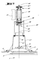
- the mower (1) shown in Figures 1 and 2 is, according to the example shown, a mower intended to be linked to the front of a vehicle motor (not shown) by means of a connecting structure (2).
- This mower (1) comprises a cutting mechanism (3) extending, during work, transverse to the direction of advance (4) at work.
- the cutting mechanism (3) consists of a housing (5) which supports a number of cutting elements (7, 7 ', 7 ") extending to the upper face (8) of the housing (5).
- Each cutting element (7,7 ', 7 ") includes cutting tools (6), and is intended to rotate about an axis of respective at least substantially vertical rotation (9, 9 ', 9 ").
- Each element of outer section (7 ', 7 ") located at the corresponding lateral end (10', 10") of the cutting mechanism (3) has a swath cover (11 ', 11 ") attached to the above said corresponding cutting element (7 '7 ").
- Each swath cover (11 ', 11 ") is conical in shape, and is fixed to the cutting element (7', 7") corresponding so that its median axis (12 ', 12 ") is at least substantially coincident with the axis of rotation (9 ', 9 ") of said cutting element (7', 7 ").
- the rotary drive of the cutting elements (7, 7 ', 7 ") is produced by drive elements not shown, housed in a manner known to man of art, inside the housing (5) of the cutting mechanism (3). Training in rotation of these drive elements (7, 7 ', 7 ") is achieved by the first cutting element (7 '), which receives the movement of a transmission (14).
- the transmission (14) has a first transmission shaft (15) with universal joints extending partially to inside the swath cover (11 ') and being fixed on the one hand on the part upper of the first cutting element (7 ') and on the other hand to a first device transmission (16).
- This transmission device (16) comprises a casing (17), an input shaft (18), an upper output shaft (19) with a longitudinal axis (20) at the less substantially vertical extending upwards and a lower output shaft (22) of longitudinal axis (23) extending downward at least substantially coincident with the longitudinal axis (20) of the upper output shaft (19), the first shaft of transmission (15) with universal joints being fixed to said lower output shaft (22).
- the longitudinal axes (20, 23) of the upper output shaft (19) and the lower output shaft (22) are at least substantially coincident with the axis of rotation (9 ') of the first cutting element (7').
- a protector (24) of cylindrical shape intended to protect the lower output shaft (22) and the first drive shaft (15) with universal joints.
- the protector (24) is fixed to the casing (17) and extends downwards towards the swath cover (11 ') so as to surround the part of the first drive shaft (15) which extends outside said swath cover (11 ').
- the axis longitudinal (25) of the protector (24) is at least substantially coincident with the axis of rotation (9 ') of the first cutting element (7').
- the transmission (14) also includes a second transmission shaft (27) with universal joints ( Figures 1 and 2) fixed on the one hand to the input shaft (18) of the first transmission device (16) and secondly to an output shaft (28) belonging to a second transmission device (29).
- This second device transmission (29) is located at least substantially in the median plane (13) of the mower (1) and comprises a casing (30) and an input shaft (32) intended to receive a universal joint drive shaft (not shown) from of the motor vehicle (not shown).
- the mower (1) according to the present invention further comprises a supporting structure (33) fixed to the cutting mechanism (3) at the fixing means (34).
- the cutting mechanism (3) - supporting structure (33) assembly is linked to the connecting structure (2) by means of a connecting device (35) comprising four connecting rods (37), and a locking device (not shown).
- the connecting rods (37) are intended, during work, to allow a certain freedom of the whole mechanism cutting (3) - supporting structure (33) relative to the connecting structure (2) of so as to allow said cutting mechanism (3) to follow the unevenness of the ground, the blocking device (not shown) is intended to lock this freedom during transport of the mower (1).
- Each connecting rod (37) is located at the corresponding lateral end (10 ', 10 ") of the cutting mechanism (3) and extends, during work, forward and upward, and is linked to the connecting structure (2) at by means of a first articulation (38) and to the support structure (33) by means a second articulation (39), said articulations (38, 39) being of the type spherical.
- the mower (1) additionally comprises a swathing device (40) formed by two guide elements (42 ', 42 ") each located at each lateral end (10 ', 10 ") of the cutting mechanism (3) and, taking account of the direction in advance (43) at work, behind the cutting front (44) of said cutting mechanism (3).
- Each guide element (42 ', 42 ") comprises, according to the example shown, two swath rotors (45, 46) arranged transversely to the direction of advance (4) at work.
- Each swath rotor (45, 46) is suspended from the structure carrier (33) by means of a respective cylindrical link (48, 49) longitudinal (50, 51) at least substantially vertical.
- Each swath rotor (45, 46) has at least one casing (52, 53) substantially cylindrical, essentially directed upwards, of longitudinal axis (54, 55) at least substantially coincident with the longitudinal axis (50, 51) of the corresponding cylindrical connection (48, 49).
- Each envelope (52, 53) has drive elements (56) distributed at least substantially uniform on the periphery thereof.
- the elements drive (56) consist of four drive ribs (57) angularly spaced at least substantially 90 °.
- Each rib drive (57) is fixed on the periphery of the envelope (52, 53) corresponding and extends along the longitudinal axis (54, 55) of the latter.
- the two swath rotors (45, 46), of the same element of guides (42 ', 42 "), are arranged relative to each other so that a horizontal straight line (62), resting on the front part of said swath rotors (45, 46), extends in top view, towards the rear in the direction of the median plane (13) of the cutting mechanism (3).
- the casing (52) of the swath rotor (45) is diameter larger than the casing (53) of the swath rotor (46).
- the envelope (52) of the outermost swath rotor (45) extends into the close proximity to the trajectories (64, 64 ', 64 ") swept by the cutting tools (6) corresponding cutting elements (7-7 ', 7-7 ").
- the longitudinal axis (50) of the cylindrical link (48) connecting the swath rotor (45), located furthest to the outside the supporting structure (33) extends at least substantially in the vertical plane (63) directed in the direction of advance (4) at work and extending midway between the axis of rotation (9 ', 9 ") of the outermost cutting element (7', 7") of the cutting mechanism (3) and the axis of rotation (9) of the adjacent cutting element (7) said cutting element (7 ', 7 ").
- the diameter of the envelope (52) of the swath rotor (45) in a view in the direction of advance (4) at work this overlaps the swath cover (11 ', 11 ") fixed on the cutting element (7', 7 ”) corresponding.
- the swath rotor (46) also has a lower part (65) essentially directed radially outward and extending to below the lower end (59) of the adjacent swath rotor (45).
- This part lower (65) has the shape of a truncated cone and has a strip (66) in flexible material (Figure 4).
- This strip (66) of flexible material is fixed to the lower end (60) of the swath rotor (46) by means of a first sheet (67), in the form of a trunk of cone, integral with the lower end of the casing (53) and a second sheet (68), also in the form of a truncated cone, fixed to said first sheet (67) at fixing means (69).
- the strip (66) is located between the two sheets (67, 68) between which it is clamped so as to follow the shape of said sheets (67, 68) and extends radially outward from the swath rotor (46) up to the lower end (59) of the adjacent swath rotor (45).
- the second sheet (68) is diametrically larger than the first sheet (67) so that it extends radially beyond said first sheet (67).
- the fixing members (69) consist of bolts (70) passing right through the sheets (67, 68) and the strip (66) of material flexible.
- swath rotors (45, 46) are intended to rotate around respective axes of rotation (71, 72) at least substantially vertical.
- the axes of rotation (71, 72) of the swath rotors (45, 46) are at least substantially coincident with the axes longitudinal (50, 51) of cylindrical connections (48, 49) connecting said rotors swath (45, 46) to the supporting structure (33).
- the swath rotors (45, 46) of an element of guide (42 ', 42 ") are rotated by means of a mechanism drive (73 ', 73 "), located above said swath rotors (45, 46) preferably located above the supporting structure (33) fixed to the mechanism cutting (3) as shown in Figures 1 and 2.
- the swath rotors (45, 46) of the elements of guide (42 ', 42 ") are rotated so as to swath the forage towards the median plane (13) of the cutting mechanism (3).
- the swath rotors (45, 46) of the guide element (42 ') rotate, in a top view ( Figure 2), in the direction of rotation (74) opposite to that of the hands of a watch and, the swath rotors (45, 46) of the element of guide (42 ") rotate, in a top view ( Figure 2), in the same direction of rotation (75) as that of the hands of a watch.
- Each drive mechanism (73 ', 73 ") has a strap transmission (76 ', 76 ") extending at least substantially horizontally above of the supporting structure (33).
- each swath rotor (45, 46) has a drive pulley (77, 78) located above the link cylindrical (48, 49) corresponding.
- the diameter of the pulley drive (77) of the swath rotor (45) is larger than the diameter of the envelope (52) corresponding, while the diameter of the drive pulley (78) of the swath rotor (46) is smaller than the diameter of the casing (53) corresponding.
- Such a design makes it possible to obtain a linear speed rake rotor device (46), located closest to the median plane (13), higher than the peripheral linear speed of the swath rotor (45) located the most outside the cutting mechanism (3).
- each drive mechanism (73 ', 73 ") is provided with a tensioner (80) intended to ensure a good tension of the belt of corresponding transmission (76 ', 76 ").
- a drive pulley (81 ') intended to drive the drive belt (76 ') of the drive mechanism (73').
- This pulley drive (81 ') is fixed in an at least substantially concentric manner on the upper output shaft (19) of the first transmission device (16) by which it is rotated.
- a second pulley is provided for this purpose.
- This second drive pulley (81") is rotated by the cutting element (7 ") by means of a transmission (82) ( Figure 5) comprising two drive shafts (83, 84).
- the transmission shaft (83), of longitudinal axis (85) at least substantially coincident with the axis of rotation (9 ") of the cutting element (7"), is linked to the supporting structure (33) at by means of a cylindrical connection (86).
- the drive pulley (81 ") At the upper end (87) of the transmission (83) is fixed, in an at least substantially concentric manner, the drive pulley (81 "). At the lower end (88) the drive shaft (83) is linked the upper part (89) of the drive shaft (84) by means of an elastic connection (90) and the lower end (91) of said shaft transmission (84) is linked to the cutting element (7 ") by means of a member drive (92) integral with the cutting element (7 ").
- each mechanism drive (73 ', 73 ") is covered by a cover (94) intended on the one hand to protect the user or other neighboring persons and on the other hand to house the drive mechanism (73 ′, 73 ′′) of external elements such as for example cut product, stones, etc ...
- the swathing device (40), equipping the mower (1) according to the embodiment shown, is symmetrical with respect to the plane median (13) of the cutting mechanism (3).
- the mower (1) as described above, operates as follows.
- the mower (1) is moved in a plot covered with products to cut.
- the plants are first cut cleanly close to the ground by the cutting tools.
- the mower (1) Depending on the width of the cutting mechanism (3), it is perfectly conceivable to equip the mower (1) with a swathing device comprising envelopes (52; 53) swath rotor (45; 46) of at least substantially equal diameters.
- the swathing device (40) can be fitted with four swath rotors (46) having envelopes (53), and when the mechanism cutting blade (3) has a relatively large working width, the swathing device (40) can be fitted with four swath rotors (45) comprising envelopes (52).
Landscapes
- Life Sciences & Earth Sciences (AREA)
- Environmental Sciences (AREA)
- Harvester Elements (AREA)
- Guiding Agricultural Machines (AREA)
- Outside Dividers And Delivering Mechanisms For Harvesters (AREA)
Claims (22)
- Mähmaschine, diedadurch gekennzeichnet, daß es sich bei den Rotoren (45, 56) um Schwadrotoren handelt, die in unmittelbarer Nähe voneinander angeordnet und nur von oben am Traggestell (33) aufgehängt sind, und daß sich das untere Ende (59, 60) eines Schwadrotors (45, 46) mindestens bis zu der durch die Schneidwerkzeuge (6) der Schneidelemente (7, 7', 7") definierten Schnittebene (61) nach unten erstreckt.eine Verbindungskonstruktion (2) zur Verbindung der Mähmaschine mit einem Motorfahrzeug;einen Schneidmechanismus (3), der mit Schneidwerkzeugen (6) aufweisenden bewegbaren Schneidelementen (7, 7', 7") versehen ist;
undeine Schwadvorrichtung (40), die das durch die Schneidelemente (7, 7', 7") geschnittene Gut seitlich zur mittleren Ebene (13) des Schneidmechanismus (3) bewegen soll, bevor es auf dem Boden abgelegt wird, wobei die Schwadvorrichtung (40) mindestens ein Element (42', 42") zur Führung des Schnittguts aufweist, das sich in der Nähe eines der Seitenenden (10', 10") des Schneidmechanismus (3) und, in Arbeitsvorschubrichtung (43) gesehen, hinter der Schnittfront (44) des Schneidmechanismus (3) befindet, wobei das Führungselement (42', 42") mindestens zwei Rotoren (45, 46) umfaßt, die quer zur Arbeitsvorschubrichtung (4) ausgerichtet sind und eine im Betrieb nach oben ausgerichtete Drehachse (71, 72) aufweisen, wobei die Rotoren (45, 46) an einem mit dem Schneidmechanismus (3) und/oder der Verbindungskonstruktion (2) verbundenen Traggestell (33) aufgehängt sind und mittels eines Antriebsmechanismus (73', 73") drehangetrieben werden; umfaßt, - Mähmaschine nach Anspruch 1, dadurch gekennzeichet, daß die Schwadrotoren (45, 46) eines gleichen Führungselements (42', 42") bezüglich einander so angeordnet sind, daß eine sich auf den Vorderteil der Schwadrotoren (45, 46) stützende horizontale Gerade, von oben gesehen, in Richtung der mittleren Ebene (13) des Schneidmechanismus (3) nach hinten verläuft.
- Mähmaschine nach Anspruch 1 oder 2, dadurch gekennzeichnet, daß der sich am nächsten zur mittleren Ebene (13) des Schneidmechanismus (3) befindende Schwadrotor (46), in Arbeitsvorschubrichtung (4) gesehen, den sich am weitesten außen befindenden Schwadrotor (45) zumindest im wesentlichen berührt oder diesen etwas überschneidet.
- Mähmaschine nach irgend einem der Ansprüche 1 bis 3, dadurch gekennzeichnet, daß sich zumindest der Schwadrotor (46), der sich am nächsten zur mittleren Ebene (13) des Schneidmechanismus (3) befindet, eine im wesentlichen nach oben ausgerichtete Umhüllung (53) und einen im wesentlichen radial nach außen gerichteten unteren Teil (65) aufweist.
- Mähmaschine nach Anspruch 4, dadurch gekennzeichnet, daß sich der im wesentlichen radial nach außen gerichtete untere Teil (65) bis unter das untere Ende (59) des benachbarten Schwadrotors (45) erstreckt.
- Mähmaschine nach Anspruch 4 oder 5, dadurch gekennzeichnet, daß der im wesentlichen radial nach außen gerichtete untere Teil (65) kegelstumpfförmig ausgebildet ist.
- Mähmaschine nach irgend einem der Ansprüche 1 bis 6, dadurch gekennzeichnet, daß der untere Teil (65) eines Schwadrotors (45, 46) aus einem flexiblen Material hergestellt ist.
- Mähmaschine nach irgend einem der Ansprüche 1 bis 7, dadurch gekennzeichnet, daß der sich am weitesten außen befindende Schwadrotor (45) eine Umhüllung (52) aufweist, die sich bis in unmittelbare Nähe der von den Werkzeugen (6) des sich am weitesten außen vom Schneidmechanismus (3) befindenden Schneidelements (7', 7") und des sich neben dem Schneidelement (7', 7") befindenden Schneidelements (7) beschriebenen Bahnen (64, 64', 64") erstreckt.
- Mähmaschine nach irgend einem der Ansprüche 1 bis 8, dadurch gekennzeichnet, daß die Drehachse (71) des sich am weitesten außen befindenden Schwadrotors (45) zumindest im wesentlichen in der in Arbeitsvorschubrichtung (4) ausgerichteten vertikalen Ebene (63) verläuft, die sich auf halbem Wege zwischen der Drehachse (9', 9") des sich am weitesten außen vom Schneidmechanismus (3) befindenden Schneidelements (7', 7") und der Drehachse (9) des sich neben dem Schneidelement (7', 7") befindenden entsprechenden Schneidelements (7) erstreckt.
- Mähmaschine nach irgend einem der Ansprüche 1 bis 9, dadurch gekennzeichnet, daß das sich an dem Ende des Schneidmechanismus (3), an dem ein Führungselement (42', 42") vorgesehen ist, befindende äußere Schneidelement (7', 7") eine Schwadabdeckung (11', 11") aufweist und daß der sich am weitesten außen befindende entsprechende Schwadrotor (45), in Arbeitsvorschubrichtung (4) gesehen, die Schwadabdeckung (11', 11") zumindest im wesentlichen berührt oder sie etwas überschneidet.
- Mähmaschine nach irgend einem der Ansprüche 1 bis 10, dadurch gekennzeichnet, daß die Drehachse (71, 72) eines Schwadrotors (45, 46) zumindest im wesentlichen vertikal verläuft.
- Mähmaschine nach irgend einem der Ansprüche 1 bis 11, dadurch gekennzeichnet, daß die Schwadrotoren (45, 46) in der Höhe verschiebbar sind.
- Mähmaschine nach den Ansprüchen 4 und 8, dadurch gekennzeichnet, daß die Umhüllung (52, 53) jedes Schwadrotors (45, 46) zumindest im wesentlichen zylindrisch ist.
- Mähmaschine nach Anspruch 13, dadurch gekennzeichnet, daß die Umhüllung (52, 53) mindestens eines der Schwadrotoren (45, 46) eines Führungselements (42', 42") zumindest im wesentlichen gleichmäßig verteilte Antriebselemente (56) enthält.
- Mähmaschine nach Anspruch 14, dadurch gekennzeichnet, daß die Antriebselemente (56) Antriebsrippen (57) sind, die sich zumindest im wesentlichen entlang einer Erzeugenden der Umhüllung (52, 53) erstrecken.
- Mähmaschine nach Anspruch 14 oder 15, dadurch gekennzeichnet, daß zumindest die Umhüllung (53) des sich am nächsten zur mittleren Ebene (13) des Schneidmechanismus (3) befindenden Schwadrotors (46) mit Antriebselementen (56) versehen ist.
- Mähmaschine nach irgend einem der Ansprüche 1 bis 16, dadurch gekennzeichnet, daß die lineare Umfangsgeschwindigkeit des sich am nächsten zur mittleren Ebene (13) befindenden Schwadrotors (46) der linearen Umfangsgeschwindigkeit des sich am weitesten außen befindenden Schwadrotors (45) gleich oder größer ist.
- Mähmaschine nach irgend einem der Ansprüche 1 bis 17, dadurch gekennzeichnet, daß sich der Antriebsmechanismus (73', 73") der Schwadrotoren (45, 46) eines Führungselements (42', 42") über den Schwadrotoren (45, 46) befindet.
- Mähmaschine nach Anspruch 18, dadurch gekennzeichnet, daß sich der Antriebsmechanismus (73', 73") über dem Traggestell (33) befindet.
- Mähmaschine nach Anspruch 18 oder 19, dadurch gekennzeichnet, daß der Antriebsmechanismus (73', 73") einen sich zumindest im wesentlichen horizontal erstreckenden Treibriemen (76', 76") umfaßt.
- Mähmaschine nach irgend einem der Ansprüche 1 bis 20, dadurch gekennzeichnet, daß an jedem Seitenende (10', 10") des Schneidmechanismus (3) ein Führungselement (42', 42") angeordnet ist, wobei diese beiden Führungselemente (42', 42") die Schwadvorrichtung (40) bilden.
- Mähmaschine nach Anspruch 21, dadurch gekennzeichnet, daß der sich an dem Ende (10'), an dem der Schneidmechanismus (3) angetrieben wird, befindende Antriebsmechanismus (73') des Führungselements (42') die Bewegung direkt von einem Kraftübertragungssystem (14) erhält, das den Schneidmechanismus (3) in Gang setzt, während der sich an dem anderen Ende (10") des Schneidmechanismus (3) befindende Antriebsmechanismus (73") des Führungselements (42") die Bewegung von dem Schneidmechanismus (3) erhält.
Applications Claiming Priority (2)
| Application Number | Priority Date | Filing Date | Title |
|---|---|---|---|
| FR9508701 | 1995-07-13 | ||
| FR9508701A FR2736505B1 (fr) | 1995-07-13 | 1995-07-13 | Faucheuse avec un dispositif d'andainage perfectionne |
Publications (2)
| Publication Number | Publication Date |
|---|---|
| EP0753246A1 EP0753246A1 (de) | 1997-01-15 |
| EP0753246B1 true EP0753246B1 (de) | 2001-09-26 |
Family
ID=9481114
Family Applications (1)
| Application Number | Title | Priority Date | Filing Date |
|---|---|---|---|
| EP96440053A Expired - Lifetime EP0753246B1 (de) | 1995-07-13 | 1996-07-01 | Mähmaschine mit einer verbesserter Schwadvorrichtung |
Country Status (6)
| Country | Link |
|---|---|
| US (1) | US5852921A (de) |
| EP (1) | EP0753246B1 (de) |
| AT (1) | ATE206002T1 (de) |
| DE (1) | DE69615472T2 (de) |
| DK (1) | DK0753246T3 (de) |
| FR (1) | FR2736505B1 (de) |
Families Citing this family (23)
| Publication number | Priority date | Publication date | Assignee | Title |
|---|---|---|---|---|
| FR2784003B1 (fr) | 1998-10-02 | 2000-12-29 | Kuhn Sa | Machine agricole comportant un timon pivotable et des organes de transmission comprenant un accouplement a joints universels |
| FR2785143B1 (fr) | 1998-10-30 | 2001-02-16 | Kuhn Sa | Machine agricole comportant un verin double a un seul cylindre |
| FR2786977B1 (fr) | 1998-12-14 | 2001-02-16 | Kuhn Sa | Faucheuse comportant un dispositif centralise de reglage de la force d'allegement exercee sur le mecanisme de recolte |
| FR2774853B1 (fr) | 1999-02-15 | 2001-02-16 | Kuhn Sa | Organe de coupe pour une machine de coupe notamment une faucheuse |
| FR2791224B1 (fr) | 1999-03-24 | 2001-05-25 | Kuhn Sa | Dispositif de coupe d'une machine de coupe, par exemple faucheuse comportant un dispositif d'entrainement du produit coupe |
| FR2792161B1 (fr) | 1999-04-16 | 2001-05-25 | Kuhn Sa | Machine de coupe comportant un dispositif de coupe lie a un chassis au moyen d'un dispositif de liaison ameliore |
| FR2792164B1 (fr) | 1999-04-16 | 2001-05-25 | Kuhn Sa | Dispositif de traitement de fourrage coupe et faucheuse utilisant un tel dispositif de traitement |
| FR2794206B1 (fr) | 1999-05-26 | 2001-07-06 | Kuhn Sa | Procede de montage/demontage et de reglage automatique de la tension d'un organe de transmission sans fin - machine agricole utilisant un tel procede |
| FR2794934B1 (fr) | 1999-06-17 | 2001-08-10 | Kuhn Sa | Machine agricole du type faucheuse ou faucheuse- conditionnneuse comportant un organe d'amortissement |
| FR2802766B1 (fr) | 1999-12-23 | 2002-09-27 | Kuhn Sa | Element de coupe d'une machine de coupe de vegetaux rotative et machine de coupe de vegetaux rotative comportant un tel element de coupe |
| US6581362B2 (en) * | 2001-06-19 | 2003-06-24 | Deere & Company | Crop converging arrangement for mower-conditioner equipped with a rotary disc cutter bar |
| FR2867350B1 (fr) * | 2004-03-09 | 2006-04-28 | Kuhn Sa | Machine de coupe, notamment une faucheuse agricole, dont la mise en position de transport est simplifiee |
| FR2885484B1 (fr) * | 2005-05-10 | 2007-06-15 | Kuhn Sa Sa | Engin agricole comportant un vehicule moteur et plusieurs unites de travail destinees a couper des produits vegetaux |
| US20080016837A1 (en) * | 2006-04-24 | 2008-01-24 | Rosenbalm Allan W | Rotary platform having converging elements for specialty crops |
| US7340876B1 (en) * | 2006-09-15 | 2008-03-11 | Macdon Industries Ltd. | Crop harvesting header with rotary disks and impellers for transferring the crop inwardly to a discharge opening |
| US7461498B1 (en) * | 2007-07-26 | 2008-12-09 | Macdon Industries Ltd. | Crop harvesting header with rotary disks and converging system for forming a swath |
| US8434290B2 (en) * | 2007-09-13 | 2013-05-07 | Macdon Industries Ltd. | Rotary disk crop harvesting header with an auger for transferring the crop |
| US8006469B2 (en) | 2007-09-13 | 2011-08-30 | Macdon Industries Ltd | Crop harvesting header with rotary disks and impellers for transferring the crop inwardly to a discharge opening |
| CN101563973B (zh) * | 2009-05-29 | 2011-02-02 | 双峰县神手微型收割机制造厂 | 防缠绕的收割机可升降下割刀装置 |
| CA2706705C (en) | 2009-07-08 | 2012-01-10 | Macdon Industries Ltd. | Rotary disk crop harvesting header with an auger and impellers for converging the crop |
| CN104996093B (zh) * | 2015-08-08 | 2017-01-25 | 安徽东升新能源科技有限公司 | 机电一体化秸秆就地旋切灭茬装置 |
| US11160206B2 (en) * | 2019-05-31 | 2021-11-02 | Deere & Company | Crop mowing implement and a converging drum therefor |
| US12232442B2 (en) * | 2022-02-23 | 2025-02-25 | Cnh Industrial America Llc | Agricultural mower conditioner with odd number of cutting discs |
Family Cites Families (57)
| Publication number | Priority date | Publication date | Assignee | Title |
|---|---|---|---|---|
| NL6507844A (de) * | 1965-06-18 | 1966-12-19 | ||
| DD96388A1 (de) * | 1970-11-09 | 1973-03-20 | ||
| US3772865A (en) * | 1972-03-06 | 1973-11-20 | Fahr Ag Maschf | Drum type mower |
| FR2317869A1 (fr) * | 1975-07-16 | 1977-02-11 | Reber Walter | Bande d'andainage pour faucheuse rotative entrainee par le bas |
| NL7700541A (en) * | 1977-01-19 | 1978-07-21 | Vicon Nv | Multi-disc rotary mower - has swath board formed by endless belt trained around two upright rollers with drive from outer cutter disc |
| US4160356A (en) * | 1978-02-06 | 1979-07-10 | Mathews B C | Drive for mower |
| FR2419006A1 (fr) * | 1978-03-10 | 1979-10-05 | Kuhn Sa | Dispositif reducteur de la largeur des andains formes par les faucheuses |
| NL7806654A (nl) * | 1978-06-20 | 1979-12-27 | Multinorm Bv | Maaiinrichting. |
| FR2458981A1 (fr) * | 1979-06-19 | 1981-01-09 | Kuhn Sa | Bati de machine agricole |
| USRE34417E (en) * | 1980-02-04 | 1993-10-26 | Kuhn S.A. | Mower having separately replaceable bearing subassembly |
| FR2496394A1 (fr) * | 1980-12-18 | 1982-06-25 | Kuhn Sa | Perfectionnement aux supports d'elements coupants des faucheuses rotatives |
| FR2496391A1 (fr) * | 1980-12-19 | 1982-06-25 | Kuhn Sa | Perfectionnement aux faucheuses |
| FR2502888A1 (fr) * | 1981-04-02 | 1982-10-08 | Kuhn Sa | Barre de coupe a protecteur de disque lateral amovible |
| FR2520970B1 (fr) * | 1982-02-08 | 1987-01-30 | Kuhn Sa | Faucheuse rotative avec arbre de transmission perfectionne et procede de realisation de cet arbre |
| FR2529744A1 (fr) * | 1982-07-09 | 1984-01-13 | Kuhn Sa | Dispositif de decrottage du carter d'une faucheuse a disques |
| FR2545315B1 (fr) * | 1983-05-03 | 1986-05-02 | Kuhn Sa | Machine agricole a dispositif de transmission de mouvement perfectionne |
| FR2562758B1 (fr) * | 1984-04-12 | 1988-05-20 | Kuhn Sa | Faucheuse |
| FR2565455B1 (fr) * | 1984-06-07 | 1986-10-03 | Kuhn Sa | Perfectionnement aux dispositifs de conditionnement de fourrage |
| FR2566992B1 (fr) * | 1984-07-06 | 1988-10-14 | Kuhn Sa | Faucheuse rotative. |
| FR2567710B1 (fr) * | 1984-07-19 | 1987-05-07 | Kuhn Sa | Procede de transformation d'une machine de recolte pour l'amener d'une position de travail dans une position de transport, et machine de recolte utilisant ce procede |
| FR2570248B1 (fr) * | 1984-09-19 | 1990-06-29 | Kuhn Sa | Faucheuse rotative |
| FR2571586B1 (fr) * | 1984-10-16 | 1994-12-09 | Kuhn Sa | Faucheuse, verin amortisseur et dispositif amortisseur equipant cette faucheuse |
| FR2572881B1 (fr) * | 1984-11-12 | 1989-04-21 | Kuhn Sa | Faucheuse comportant un chassis muni d'une structure intermediaire et de moyens destines a empecher l'accrochage de fourrage a la dite structure intermediaire. |
| DE3501133A1 (de) * | 1985-01-15 | 1986-07-17 | Klöckner-Humboldt-Deutz AG Zweigniederlassung Fahr, 7702 Gottmadingen | Kreiselmaeher |
| FR2594627B1 (fr) * | 1986-02-27 | 1988-06-17 | Kuhn Sa | Faucheuse rotative |
| FR2579405B1 (fr) * | 1985-03-28 | 1987-06-19 | Kuhn Sa | Machine agricole a dispositif de transmission perfectionne |
| FR2583258B1 (fr) * | 1985-06-17 | 1987-09-18 | Kuhn Sa | Faucheuse rotative |
| FR2590441B2 (fr) * | 1985-07-10 | 1989-05-26 | Kuhn Sa | Faucheuse perfectionnee |
| FR2584889B1 (fr) * | 1985-07-18 | 1989-05-05 | Kuhn Sa | Faucheuse avec mecanisme de delestage |
| FR2597293B1 (fr) * | 1986-04-17 | 1988-08-05 | Kuhn Sa | Faucheuse rotative avec barre de coupe et structure support. |
| FR2598058B1 (fr) * | 1986-05-02 | 1989-10-13 | Kuhn Sa | Faucheuse munie d'au moins un organe de coupe surmonte par un tambour rotatif |
| FR2608362B1 (fr) * | 1986-12-22 | 1990-10-12 | Kuhn Sa | Faucheuse avec dispositif de suspension des groupes de fauche perfectionne |
| FR2617003B1 (fr) * | 1987-06-26 | 1991-06-28 | Kuhn Sa | Faucheuse-conditionneuse perfectionnee |
| FR2617002B1 (fr) * | 1987-06-26 | 1991-06-07 | Kuhn Sa | Faucheuse munie de deux groupes d'organes de fauchage |
| FR2624688B1 (fr) * | 1987-12-21 | 1990-05-18 | Kuhn Sa | Faucheuse avec rigidification perfectionnee de la barre de coupe |
| FR2626137B1 (fr) * | 1988-01-22 | 1991-09-06 | Kuhn Sa | Faucheuse rotative comportant des organes de coupe s'etendant au-dessus d'un carter par l'intermediaire de paliers de guidage et d'entrainement |
| FR2627942B1 (fr) * | 1988-03-04 | 1990-08-10 | Kuhn Sa | Perfectionnement aux machines agricoles pour la recolte |
| FR2628596B1 (fr) * | 1988-03-15 | 1991-09-06 | Kuhn Sa | Faucheuse a entrainement direct |
| FR2635433B1 (fr) * | 1988-08-18 | 1991-02-01 | Kuhn Sa | Faucheuse a chassis perfectionne |
| FR2636203B1 (fr) * | 1988-09-13 | 1990-11-30 | Kuhn Sa | Faucheuse avec patins perfectionnes |
| FR2638056B1 (fr) * | 1988-10-26 | 1991-06-07 | Kuhn Sa | Faucheuse avec montage perfectionne des organes de coupe |
| FR2642610B1 (fr) * | 1989-02-07 | 1991-05-17 | Kuhn Sa | Faucheuse avec dispositif de securite a declenchement |
| FR2654893B1 (fr) * | 1989-11-24 | 1992-02-21 | Kuhn Sa | Machine agricole avec dispositif de suspension du groupe d'organes de travail perfectionne. |
| FR2654896B1 (fr) * | 1989-11-24 | 1992-02-21 | Kuhn Sa | Faucheuse comportant un groupe d'organes de travail s'etendant au travail transversalement a la direction d'avance. |
| FR2654897B1 (fr) * | 1989-11-24 | 1992-03-20 | Kuhn Sa | Faucheuse avec dispositif d'allegement perfectionne. |
| FR2660519B1 (fr) * | 1990-04-05 | 1992-09-18 | Kuhn Sa | Faucheuse a chassis perfectionne. |
| FR2660518B1 (fr) * | 1990-04-05 | 1993-06-11 | Kuhn Sa | Machine agricole avec dispositif de detection de la position intermediaire du moyen de liaison. |
| FR2668880B1 (fr) * | 1990-11-12 | 1995-06-30 | Kuhn Sa | Procede de transformation d'une machine de recolte pour l'amener d'une position de transport dans une position de travail, et machine de recolte. |
| FR2668881B1 (fr) * | 1990-11-12 | 1994-05-27 | Kuhn Sa | Machine agricole, en particulier faucheuse, s'adaptant aisement au relief du terrain et comportant un carter pivotant. |
| FR2675980B1 (fr) * | 1991-04-30 | 1998-07-03 | Kuhn Sa | Machine de coupe perfectionnee avec structure d'attelage pivotante. |
| FR2686216B1 (fr) * | 1992-01-17 | 1994-04-29 | Kuhn Sa | Faucheuse a delestage dynamique. |
| FR2687039B1 (fr) * | 1992-02-12 | 1994-04-29 | Kuhn Sa | Faucheuse avec un dispositif de verrouillage perfectionne. |
| FR2691041B1 (fr) * | 1992-05-14 | 1999-02-26 | Kuhn Sa | Machine de coupe, notamment faucheuse, s'adaptant aisement au relief du sol. |
| FR2691037B1 (fr) * | 1992-05-14 | 1999-02-26 | Kuhn Sa | Machine agricole, notamment faucheuse, avec un dispositif de delestage et de levage perfectionne. |
| FR2696898B1 (fr) * | 1992-10-16 | 1994-12-09 | Kuhn Sa | Faucheuse avec un entraînement perfectionné des rouleaux de traitement. |
| IT1260425B (it) * | 1992-12-07 | 1996-04-05 | Dispositivo condizionatore di foraggio per piegamento | |
| FR2715797B1 (fr) * | 1994-02-08 | 1996-04-12 | Kuhn Sa | Faucheuse rotative avec barre de coupe et structure support. |
-
1995
- 1995-07-13 FR FR9508701A patent/FR2736505B1/fr not_active Expired - Fee Related
-
1996
- 1996-07-01 EP EP96440053A patent/EP0753246B1/de not_active Expired - Lifetime
- 1996-07-01 AT AT96440053T patent/ATE206002T1/de active
- 1996-07-01 DE DE69615472T patent/DE69615472T2/de not_active Expired - Lifetime
- 1996-07-01 DK DK96440053T patent/DK0753246T3/da active
- 1996-07-10 US US08/679,159 patent/US5852921A/en not_active Expired - Lifetime
Also Published As
| Publication number | Publication date |
|---|---|
| ATE206002T1 (de) | 2001-10-15 |
| EP0753246A1 (de) | 1997-01-15 |
| US5852921A (en) | 1998-12-29 |
| DE69615472T2 (de) | 2002-05-23 |
| DE69615472D1 (de) | 2001-10-31 |
| FR2736505B1 (fr) | 1997-09-26 |
| FR2736505A1 (fr) | 1997-01-17 |
| DK0753246T3 (da) | 2002-01-21 |
Similar Documents
| Publication | Publication Date | Title |
|---|---|---|
| EP0753246A1 (de) | Mähmaschine mit einer verbesserter Schwadvorrichtung | |
| EP0245186B1 (de) | Mähvorrichtung | |
| EP0337909B1 (de) | Direktangetriebene Mähmaschine | |
| FR2476972A1 (de) | ||
| EP0821870B1 (de) | Mähmaschine mit Aufbereiter | |
| EP0184533A1 (de) | Mähmaschine mit einer Zwischenstruktur und Mittel zum Verhüten eines Futterstaus | |
| EP0206965B1 (de) | Rotationsmäher | |
| EP0322327B1 (de) | Mähwerk mit versteiftem Mähbalken | |
| FR2663189A1 (fr) | Machine de fenaison pour l'andainage, comportant au moins deux roues rateleuses. | |
| EP0213052B1 (de) | Mähmaschine | |
| FR2674096A1 (fr) | Appareil de coupe, en particulier pour graminacees. | |
| FR2589669A1 (fr) | Faucheuse rotative | |
| FR2577105A1 (fr) | Tondeuse a gazon motorisee | |
| CA1079074A (fr) | Faucheuses-conditionneuses | |
| EP0064115B2 (de) | Mäh- und Konditioniereinrichtung | |
| EP0090120A1 (de) | Bindevorrichtung mittels zwei Bindfäden für Rundballenpresse | |
| FR2642260A1 (fr) | Faucheuse | |
| EP0558431B1 (de) | Mähmaschine mit einem verbesserten Schutzorgan | |
| EP0517633B1 (de) | Verbesserte Mähmaschine | |
| EP0680688A1 (de) | Heuwerbungsmaschine, insbesondere ein Schwader für Futter | |
| EP3612016A1 (de) | Schwadbelüftervorrichtung und mit solch einer vorrichtung ausgestattete landwirtschaftliche maschine | |
| EP0511125A1 (de) | Sammelebene von Erntemaschine für Beeren und Früchten | |
| FR2582900A1 (fr) | Faucheuse. | |
| EP0685150A1 (de) | Vorrichtung zum Sammeln von kleinen an Boden liegenden landwirtschaftlichen Produkten wie Obst | |
| EP0442833B1 (de) | Heuwerbungsmaschine mit verbesserter Schutzvorrichtung |
Legal Events
| Date | Code | Title | Description |
|---|---|---|---|
| PUAI | Public reference made under article 153(3) epc to a published international application that has entered the european phase |
Free format text: ORIGINAL CODE: 0009012 |
|
| AK | Designated contracting states |
Kind code of ref document: A1 Designated state(s): AT CH DE DK FR GB IT LI NL |
|
| 17P | Request for examination filed |
Effective date: 19970630 |
|
| GRAG | Despatch of communication of intention to grant |
Free format text: ORIGINAL CODE: EPIDOS AGRA |
|
| GRAG | Despatch of communication of intention to grant |
Free format text: ORIGINAL CODE: EPIDOS AGRA |
|
| GRAH | Despatch of communication of intention to grant a patent |
Free format text: ORIGINAL CODE: EPIDOS IGRA |
|
| 17Q | First examination report despatched |
Effective date: 20000914 |
|
| GRAH | Despatch of communication of intention to grant a patent |
Free format text: ORIGINAL CODE: EPIDOS IGRA |
|
| GRAH | Despatch of communication of intention to grant a patent |
Free format text: ORIGINAL CODE: EPIDOS IGRA |
|
| GRAA | (expected) grant |
Free format text: ORIGINAL CODE: 0009210 |
|
| AK | Designated contracting states |
Kind code of ref document: B1 Designated state(s): AT CH DE DK FR GB IT LI NL |
|
| PG25 | Lapsed in a contracting state [announced via postgrant information from national office to epo] |
Ref country code: GB Free format text: LAPSE BECAUSE OF FAILURE TO SUBMIT A TRANSLATION OF THE DESCRIPTION OR TO PAY THE FEE WITHIN THE PRESCRIBED TIME-LIMIT Effective date: 20010926 |
|
| REF | Corresponds to: |
Ref document number: 206002 Country of ref document: AT Date of ref document: 20011015 Kind code of ref document: T |
|
| REG | Reference to a national code |
Ref country code: CH Ref legal event code: EP |
|
| REF | Corresponds to: |
Ref document number: 69615472 Country of ref document: DE Date of ref document: 20011031 |
|
| REG | Reference to a national code |
Ref country code: DK Ref legal event code: T3 |
|
| GBV | Gb: ep patent (uk) treated as always having been void in accordance with gb section 77(7)/1977 [no translation filed] |
Effective date: 20010926 |
|
| PLBE | No opposition filed within time limit |
Free format text: ORIGINAL CODE: 0009261 |
|
| STAA | Information on the status of an ep patent application or granted ep patent |
Free format text: STATUS: NO OPPOSITION FILED WITHIN TIME LIMIT |
|
| 26N | No opposition filed | ||
| REG | Reference to a national code |
Ref country code: FR Ref legal event code: PLFP Year of fee payment: 20 |
|
| PGFP | Annual fee paid to national office [announced via postgrant information from national office to epo] |
Ref country code: CH Payment date: 20150622 Year of fee payment: 20 Ref country code: DK Payment date: 20150624 Year of fee payment: 20 |
|
| PGFP | Annual fee paid to national office [announced via postgrant information from national office to epo] |
Ref country code: FR Payment date: 20150625 Year of fee payment: 20 Ref country code: NL Payment date: 20150622 Year of fee payment: 20 |
|
| PGFP | Annual fee paid to national office [announced via postgrant information from national office to epo] |
Ref country code: DE Payment date: 20150623 Year of fee payment: 20 |
|
| PGFP | Annual fee paid to national office [announced via postgrant information from national office to epo] |
Ref country code: AT Payment date: 20150624 Year of fee payment: 20 |
|
| PGFP | Annual fee paid to national office [announced via postgrant information from national office to epo] |
Ref country code: IT Payment date: 20150629 Year of fee payment: 20 |
|
| REG | Reference to a national code |
Ref country code: DE Ref legal event code: R071 Ref document number: 69615472 Country of ref document: DE |
|
| REG | Reference to a national code |
Ref country code: DK Ref legal event code: EUP Effective date: 20160701 |
|
| REG | Reference to a national code |
Ref country code: NL Ref legal event code: MK Effective date: 20160630 |
|
| REG | Reference to a national code |
Ref country code: CH Ref legal event code: PL |
|
| REG | Reference to a national code |
Ref country code: AT Ref legal event code: MK07 Ref document number: 206002 Country of ref document: AT Kind code of ref document: T Effective date: 20160701 |