EP0753247A1 - Machine de travail agricole, notamment faneuse à plusieurs rotors - Google Patents
Machine de travail agricole, notamment faneuse à plusieurs rotors Download PDFInfo
- Publication number
- EP0753247A1 EP0753247A1 EP96108137A EP96108137A EP0753247A1 EP 0753247 A1 EP0753247 A1 EP 0753247A1 EP 96108137 A EP96108137 A EP 96108137A EP 96108137 A EP96108137 A EP 96108137A EP 0753247 A1 EP0753247 A1 EP 0753247A1
- Authority
- EP
- European Patent Office
- Prior art keywords
- rotors
- machine according
- wheels
- agricultural machine
- support arms
- Prior art date
- Legal status (The legal status is an assumption and is not a legal conclusion. Google has not performed a legal analysis and makes no representation as to the accuracy of the status listed.)
- Granted
Links
- 230000005540 biological transmission Effects 0.000 claims description 2
- 239000010720 hydraulic oil Substances 0.000 claims description 2
- 230000008878 coupling Effects 0.000 description 5
- 238000010168 coupling process Methods 0.000 description 5
- 238000005859 coupling reaction Methods 0.000 description 5
- 210000000078 claw Anatomy 0.000 description 4
- 239000002689 soil Substances 0.000 description 4
- 230000006978 adaptation Effects 0.000 description 2
- 238000010276 construction Methods 0.000 description 1
- 230000001419 dependent effect Effects 0.000 description 1
- 230000000694 effects Effects 0.000 description 1
- 230000002349 favourable effect Effects 0.000 description 1
- 230000005484 gravity Effects 0.000 description 1
- 238000000034 method Methods 0.000 description 1
- 230000010355 oscillation Effects 0.000 description 1
- 238000007789 sealing Methods 0.000 description 1
Images




Classifications
-
- A—HUMAN NECESSITIES
- A01—AGRICULTURE; FORESTRY; ANIMAL HUSBANDRY; HUNTING; TRAPPING; FISHING
- A01D—HARVESTING; MOWING
- A01D78/00—Haymakers with tines moving with respect to the machine
- A01D78/08—Haymakers with tines moving with respect to the machine with tine-carrying rotary heads or wheels
- A01D78/10—Haymakers with tines moving with respect to the machine with tine-carrying rotary heads or wheels the tines rotating about a substantially vertical axis
- A01D78/1007—Arrangements to facilitate transportation specially adapted therefor
Definitions
- the invention relates to an agricultural machine that is pulled by a tractor, or is carried in the transport position by the tractor via the three-point hitch, in particular a multi-rotor tedder, according to the preambles of claims 1, 2 and 9.
- DE-OS 41 28 501 describes a haymaking machine with 8 rotatable rotary rakes, which is coupled to the three-point lifting device of a tractor via a support frame.
- a plurality of side supports articulated to one another for further rotary rakes are articulated to a central support with 2 rotary rakes, each side support being assigned a rotary rake, and the side supports being pivotable from the wide working position to a transport position which reduces the machine width.
- the first side supports adjacent to the center support and the adjoining second side supports can each be pivoted backwards about approximately horizontal axes parallel to the direction of travel, and the third side supports adjacent to the second side supports can each be pivoted about vertical folding axes.
- a disadvantage of this design in addition to the large transport height, is the relief of the front wheels of the tractor in the transport position, and the unconditional presence of a sufficiently strong three-point hydraulic system.
- the drive shafts for the tine rotors are connected via claw couplings, double universal joints or gear drives. Since the claw coupling connections (US-A 3583139) cause an interruption of the drive when swiveling from the working to the transport position, a time-consuming connection of the two coupling parts must be carried out by turning the tine rotors by hand when the drive connection is restored in the working position.
- the vertical pivot axis lies outside the rotary gear axis, so that the transport width is inevitably increased when pivoting. In particular, this has a disadvantageous effect on large diameters of the tine rotors.
- the vertical and horizontal gear pivot axis is so closely linked with the gear output shaft that they can only assume a certain position.
- the vertical swivel axis can only run concentrically with the axis of the tine rotor, while with the claw coupling connections and double universal joints it can only be arranged eccentrically and lies outside the rotor gearbox.
- the horizontal transverse axis required for ground adaptation is always outside the rotor gear in the top view for reasons of space.
- the drive shafts run inside the connecting joint frame.
- the invention has for its object to carry out the pivoting device for the lateral tine rotors with little technical effort so that small dimensions in width and height can be achieved in the transport position, as well as increased driving stability and advantageous drive connections are created in the pivot axes of the tine rotors .
- a drawbar (4) and a connection (5) for an articulated shaft (6) to the tractor (2) are arranged on a rigid longitudinal beam (3) running in the direction of travel.
- the drawbar (4) is articulated on the side member (3) on an axis (7) extending transversely to the direction of travel, which enables oscillation in a limited area and thereby compensates for uneven ground between the tractor (2) and the side member (3).
- the drawbar (4) is connected to the two-point hitch (8) of the tractor (2).
- a central frame (9) is attached transversely to the latter.
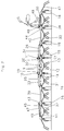
- center frame (9) On the center frame (9) are connected on both sides via connecting frames (25, 26) about a vertical pivot axis (10, 11) and interconnected support arms (39, 40, 49, 50, 49 ', 50') with tine rotors arranged thereon (31, 32, 37, 38, 41, 42, 41 ', 42').
- Two center rotors (12, 13) are arranged on the central frame (9).
- the middle frame (9) is provided with two height-adjustable transport wheels (14, 15), which are attached below the middle gyroscope (12, 13) and which are in constant contact with the ground in the transport and working positions. In the working position, the transport wheels (14, 15) simultaneously act as feeler wheels.
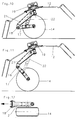
- transport wheels (14, 15) In comparison to the other feeler wheels (16), the two transport wheels (14, 15) have larger dimensions in terms of diameter and width, as well as a higher load capacity (FIG. 8).
- Transport wheels (14, 15) are attached to a swiveling wheel holder (17) (FIGS. 10, 11, 12), which is arranged on a rigid support arm (21) connected to the rotary drives (19, 20) via a swivel axis (18).
- a hydraulic cylinder (22) is arranged between the support arm (21) and the wheel holder (17), by means of which the distance of the center rotors (12, 13) from the ground is set in the working and transport position.
- the hydraulic oil line to the hydraulic cylinder (22) can run both centrally through the vertical axis of the rotary gearbox (19, 20) and through a groove arranged on the outside.
- the two transport wheels (14, 15) have a larger track width than the adjacent feeler wheels (16) (FIGS. 8, 9).
- Two cross struts (23, 24) are arranged on the side member (3) (FIGS. 3, 5), which in the transport position serve as saddle supports for the tine rotors pivoted forward.
- the cross struts (23, 24) can be fixed rigidly or in a manner not shown in detail, for example by means of hydraulic cylinders, so that they can be pivoted on the side member (3).
- a hydraulic cylinder (27, 28) is arranged between the longitudinal beam (3) and the lateral connecting frame (25, 26). The hydraulic tines (27, 28) are used to pivot the lateral tine rotors around the vertical swivel axes (10, 11) arranged on the central frame (9) from the working position to the transport position by approximately 90 °.
- the tine rotors In the pivoted position, the tine rotors rest on the cross struts (23, 24) of the side member (3), taking an approximately parallel position to the side member (3). In the transport position, small dimensions in width and height are achieved, and safe driving stability is achieved through a low center of gravity and a favorable mass distribution.
- the outer rotors then assume a vertical position (41, 42) or horizontal head position (41 ', 42') in the pivoted position. A low transport height is also achieved in this swivel position.
- one or more feeler wheels (51) are expediently arranged in the central region of the side member (3), which are supported on the field soil in the working position and permit soil copying (FIG. 4). This is particularly advantageous if there is a large distance between the tractor attachment and the tine rotors. In the transport position, the feeler wheels are pivoted upwards in a manner not shown and the ground copy is thus removed.
- the feeler wheels (51) are designed as rigid or swiveling trailing wheels. To ensure the function of the soil copying, the drawbar (4) must have the required freedom of movement in the vertical direction (possibility of swiveling around the axis (7) in a limited area).
- the individual tine rotors are driven from the tractor (2) via a cardan shaft (6). From this, the rotary movement is forwarded via a drive shaft (29) (FIG. 1) arranged below the longitudinal beam (3) to the input gear (30) on the central frame (9) (FIGS. 7 and 8). Shafts running on both sides within the central frame (9) adjoin the input gear (30), which lead to the centrifugal gears (19, 20) of the rigidly interconnected central circles (12, 13). Both shafts therefore run transversely to the direction of travel, both in the working and in the transport position.
- the drive is continued from the center rotors (12, 13) to the adjacent first side rotors (31, 32) via cardan shafts (33, 34).
- An articulated connecting frame (25, 26) with two horizontal swivel axes (35, 36) is arranged between the vertical swivel axes (10, 11) above the center rotors (12, 13) and the first side rotors (31, 32). The drive and the frame are thus separated from each other.
- the connecting frame (25, 26) is arranged above the cardan shafts (33, 34). Since the vertical swivel axes (10, 11) spatially, the closed gyro gear (19, 20) and also the gyro drive no longer touch, they can take up both concentric and any eccentric position above the gyro (19, 20).
- a design-related position laterally in front of the rotary drives (19, 20) is also easily possible.
- the connecting frame (25, 26) can also run laterally in front of the rotary drives (19, 20) and the cardan shafts (33, 34).
- the horizontal swivel axes (35, 36) lying in the direction of travel can also be easily arranged.
- Rigid support arms (39, 40) with a likewise rigid drive connection are arranged between the first side rotors (31, 32) and the second side rotors (37, 38). Adequate adjustment of the tine rotors to uneven floors is still guaranteed.
- the rigid design of the support arms (39, 40) makes saddling onto the cross struts (23, 24) of the side member (3) considerably easier.
- the outer rotors (41, 42) adjoining the second side rotors (37, 38) are connected in an articulated and pivotable manner to horizontal axes (45, 46) in the region of the rotor gears (43, 44) of the second side rotors (37, 38).
- the outer rotors (41, 42) are pivoted by approximately 90 ° by means of hydraulic cylinders (47, 48) which are articulated above the support arms (49, 50) on the centrifugal gears (43, 44).
- the drive shafts to the outer rotors (41, 42) are also articulated to the horizontal axes (45, 46) of the centrifugal gears (43, 44).
- one or more external rotors (41, 42, 41 ', 42') are connected to the second side rotors (37, 38).
- one of the two hydraulic cylinders (27, 28) arranged between the side member (3) and the connecting frame (25, 26) is optionally selected after releasing a mechanical lock ) extended further so that the desired inclination of the side tine rotors is achieved.
- the feeler wheels (16) of the side and outer rotors (31, 32; 37, 38; 41, 42; 41 ', 42') are designed as lockable trailing wheels. While the feeler wheels (16) can run freely on the inclined side, the other feeler wheels (16) are locked for tracking in the direction of travel.
Landscapes
- Life Sciences & Earth Sciences (AREA)
- Environmental Sciences (AREA)
- Agricultural Machines (AREA)
- Soil Working Implements (AREA)
- Guiding Agricultural Machines (AREA)
- Medicines Containing Plant Substances (AREA)
- Pharmaceuticals Containing Other Organic And Inorganic Compounds (AREA)
- Transplanting Machines (AREA)
Applications Claiming Priority (2)
| Application Number | Priority Date | Filing Date | Title |
|---|---|---|---|
| DE19525344 | 1995-07-12 | ||
| DE19525344A DE19525344A1 (de) | 1995-07-12 | 1995-07-12 | Landwirtschaftliche Arbeitsmaschine, insbesondere Vielkreiselheuwender |
Publications (2)
| Publication Number | Publication Date |
|---|---|
| EP0753247A1 true EP0753247A1 (fr) | 1997-01-15 |
| EP0753247B1 EP0753247B1 (fr) | 2001-09-05 |
Family
ID=7766612
Family Applications (1)
| Application Number | Title | Priority Date | Filing Date |
|---|---|---|---|
| EP96108137A Expired - Lifetime EP0753247B1 (fr) | 1995-07-12 | 1996-05-22 | Machine de travail agricole, notamment faneuse à plusieurs rotors |
Country Status (5)
| Country | Link |
|---|---|
| EP (1) | EP0753247B1 (fr) |
| AT (2) | ATE205046T1 (fr) |
| DE (2) | DE19525344A1 (fr) |
| FR (2) | FR2736503B1 (fr) |
| NL (1) | NL1003572C2 (fr) |
Cited By (12)
| Publication number | Priority date | Publication date | Assignee | Title |
|---|---|---|---|---|
| EP0806133A1 (fr) * | 1996-05-07 | 1997-11-12 | Claas Saulgau Gmbh | Dispositif pour pivoter les roues râteleuses d'une machine de fenaison |
| NL1006989C2 (nl) * | 1997-09-10 | 1999-03-11 | Maasland Nv | Opklapbare inrichting voor het bewerken van zich op de grond bevindend gewas. |
| EP0903067A3 (fr) * | 1997-09-10 | 1999-04-28 | Maasland N.V. | Appareil pliable pour traiter de la récolte couchée sur terre |
| EP0951818A1 (fr) | 1998-04-24 | 1999-10-27 | Kverneland Gottmadingen GmbH & Co. KG | Machine de fenaison |
| EP1493323A1 (fr) * | 2003-07-04 | 2005-01-05 | Maschinenfabrik Bernard Krone GmbH | Machine de fenaison |
| EP1498020A1 (fr) | 2003-07-16 | 2005-01-19 | Maschinenfabrik Bernard Krone GmbH | Machine de fenaison |
| EP1829444A1 (fr) * | 2006-03-02 | 2007-09-05 | Fella-Werke GmbH & Co. KG | Andaineuse rotative |
| EP1839480A1 (fr) * | 2006-03-28 | 2007-10-03 | Claas Saulgau Gmbh | Andaineuse rotative |
| AT13221U1 (de) * | 2007-11-05 | 2013-08-15 | Lely Patent Nv | Gezogene landwirtschaftliche Maschine |
| DE102016103475A1 (de) * | 2016-02-26 | 2017-08-31 | Claas Saulgau Gmbh | Landwirtschaftliches Arbeitsgerät und Verfahren zum Ausführen einer Bodenanpassung in der Erntestellung desselben |
| FR3082389A1 (fr) * | 2018-06-18 | 2019-12-20 | Kuhn S.A. | Machine de fenaison avec largeur de projection controlee |
| EP3915350A1 (fr) * | 2020-05-26 | 2021-12-01 | McHale Engineering | Appareil de tedder |
Families Citing this family (3)
| Publication number | Priority date | Publication date | Assignee | Title |
|---|---|---|---|---|
| DE19628619A1 (de) * | 1996-07-16 | 1998-01-22 | Claas Saulgau Gmbh | Landwirtschaftliche Arbeitsmaschine, insbesondere Mehrkreiselschwader oder -Wender |
| DE10330385B4 (de) * | 2003-07-04 | 2010-01-28 | Maschinenfabrik Bernard Krone Gmbh | Heuwerbungsmaschine |
| DE202019003996U1 (de) | 2019-09-30 | 2021-01-04 | Maschinenfabrik Bernard Krone GmbH & Co. KG | Formteil für eine Komponente, Komponente mit dem Formteil und landwirtschaftliche Arbeitsmaschine mit der Komponente |
Citations (3)
| Publication number | Priority date | Publication date | Assignee | Title |
|---|---|---|---|---|
| DE4128501A1 (de) * | 1991-08-28 | 1993-03-04 | Krone Bernhard Gmbh Maschf | Heuwerbungsmaschine |
| EP0536071A1 (fr) * | 1991-10-04 | 1993-04-07 | Kuhn S.A. | Machine de fenaison, notamment une faneuse de végétaux, avec au moins deux positions de travail |
| EP0571794A1 (fr) * | 1992-05-26 | 1993-12-01 | Claas Saulgau Gmbh | Machine à travaille agricole, notamment faneuse rotatoire |
Family Cites Families (13)
| Publication number | Priority date | Publication date | Assignee | Title |
|---|---|---|---|---|
| US3760575A (en) * | 1972-04-18 | 1973-09-25 | G H Grimm Co Inc | Hay tedding machine |
| NL158995C (nl) * | 1975-02-04 | 1982-04-16 | Zweegers P | Landbouwwerktuig, voorzien van aandrijfbare harkwielen. |
| DE3535887A1 (de) * | 1985-10-08 | 1987-04-09 | Weidtmann Rainer Dipl Ing Dipl | Heuwerbungsmaschine |
| DE3543264A1 (de) * | 1985-12-06 | 1987-06-11 | Kloeckner Humboldt Deutz Ag | Kreiselzettwender |
| DE3717307A1 (de) * | 1987-05-22 | 1988-12-15 | Kloeckner Humboldt Deutz Ag | Landmaschine, insbesondere ein kreiselzettwender |
| FR2621213B1 (fr) * | 1987-10-01 | 1990-01-05 | Kuhn Sa | Machine de fenaison avec un dispositif de protection perfectionne |
| DE3911296A1 (de) * | 1989-04-07 | 1990-10-11 | Claas Saulgau Gmbh | Landwirtschaftliche arbeitsmaschine |
| DE9000137U1 (de) * | 1990-01-08 | 1990-03-01 | Wilhelm Stoll Maschinenfabrik Gmbh, 3325 Lengede | Heuwerbungsmaschine |
| DE9010179U1 (de) * | 1990-07-04 | 1990-09-20 | H. Niemeyer Söhne GmbH & Co KG, 4446 Hörstel | Heuwerbungsmaschine |
| DE4114681A1 (de) * | 1991-05-06 | 1992-11-12 | Leipzig Bodenbearbeitung Veb | Bodenbearbeitungsgeraet mit abrollenden werkzeugen |
| FR2705861B1 (fr) * | 1993-06-04 | 1995-08-18 | Kuhn Sa | Machine de fenaison avec un dispositif de transport déplaçable. |
| DE29507032U1 (de) * | 1995-04-26 | 1995-06-29 | Fella-Werke Gmbh, 90537 Feucht | Kreiselheuwerbungsmaschine |
| DE19541355A1 (de) * | 1995-11-07 | 1997-05-15 | Claas Saulgau Gmbh | Verfahren und Vorrichtung zum Schwenken von Zinkenkreiseln für Vielkreiselheuwender |
-
1995
- 1995-07-12 DE DE19525344A patent/DE19525344A1/de not_active Withdrawn
-
1996
- 1996-05-22 EP EP96108137A patent/EP0753247B1/fr not_active Expired - Lifetime
- 1996-05-22 AT AT96108137T patent/ATE205046T1/de active
- 1996-05-22 DE DE59607615T patent/DE59607615D1/de not_active Expired - Lifetime
- 1996-06-05 AT AT0097596A patent/AT406629B/de not_active IP Right Cessation
- 1996-07-09 FR FR9608513A patent/FR2736503B1/fr not_active Expired - Fee Related
- 1996-07-11 NL NL1003572A patent/NL1003572C2/nl not_active IP Right Cessation
-
1997
- 1997-02-19 FR FR9701950A patent/FR2746576B1/fr not_active Expired - Fee Related
Patent Citations (3)
| Publication number | Priority date | Publication date | Assignee | Title |
|---|---|---|---|---|
| DE4128501A1 (de) * | 1991-08-28 | 1993-03-04 | Krone Bernhard Gmbh Maschf | Heuwerbungsmaschine |
| EP0536071A1 (fr) * | 1991-10-04 | 1993-04-07 | Kuhn S.A. | Machine de fenaison, notamment une faneuse de végétaux, avec au moins deux positions de travail |
| EP0571794A1 (fr) * | 1992-05-26 | 1993-12-01 | Claas Saulgau Gmbh | Machine à travaille agricole, notamment faneuse rotatoire |
Cited By (14)
| Publication number | Priority date | Publication date | Assignee | Title |
|---|---|---|---|---|
| EP0806133A1 (fr) * | 1996-05-07 | 1997-11-12 | Claas Saulgau Gmbh | Dispositif pour pivoter les roues râteleuses d'une machine de fenaison |
| NL1006989C2 (nl) * | 1997-09-10 | 1999-03-11 | Maasland Nv | Opklapbare inrichting voor het bewerken van zich op de grond bevindend gewas. |
| EP0903067A3 (fr) * | 1997-09-10 | 1999-04-28 | Maasland N.V. | Appareil pliable pour traiter de la récolte couchée sur terre |
| EP0951818A1 (fr) | 1998-04-24 | 1999-10-27 | Kverneland Gottmadingen GmbH & Co. KG | Machine de fenaison |
| EP1493323A1 (fr) * | 2003-07-04 | 2005-01-05 | Maschinenfabrik Bernard Krone GmbH | Machine de fenaison |
| EP1498020A1 (fr) | 2003-07-16 | 2005-01-19 | Maschinenfabrik Bernard Krone GmbH | Machine de fenaison |
| EP1829444A1 (fr) * | 2006-03-02 | 2007-09-05 | Fella-Werke GmbH & Co. KG | Andaineuse rotative |
| EP1839480A1 (fr) * | 2006-03-28 | 2007-10-03 | Claas Saulgau Gmbh | Andaineuse rotative |
| AT13221U1 (de) * | 2007-11-05 | 2013-08-15 | Lely Patent Nv | Gezogene landwirtschaftliche Maschine |
| AT13227U1 (de) * | 2007-11-05 | 2013-08-15 | Lely Patent Nv | Gezogene landwirtschaftliche Maschine |
| DE102016103475A1 (de) * | 2016-02-26 | 2017-08-31 | Claas Saulgau Gmbh | Landwirtschaftliches Arbeitsgerät und Verfahren zum Ausführen einer Bodenanpassung in der Erntestellung desselben |
| DE102016103475B4 (de) | 2016-02-26 | 2023-12-28 | Claas Saulgau Gmbh | Landwirtschaftliches Vorsatzgerät |
| FR3082389A1 (fr) * | 2018-06-18 | 2019-12-20 | Kuhn S.A. | Machine de fenaison avec largeur de projection controlee |
| EP3915350A1 (fr) * | 2020-05-26 | 2021-12-01 | McHale Engineering | Appareil de tedder |
Also Published As
| Publication number | Publication date |
|---|---|
| FR2736503B1 (fr) | 1999-09-10 |
| AT406629B (de) | 2000-07-25 |
| DE19525344A1 (de) | 1997-01-16 |
| DE59607615D1 (de) | 2001-10-11 |
| FR2746576B1 (fr) | 2000-01-07 |
| NL1003572A1 (nl) | 1997-01-14 |
| ATA97596A (de) | 1999-12-15 |
| ATE205046T1 (de) | 2001-09-15 |
| FR2746576A1 (fr) | 1997-10-03 |
| EP0753247B1 (fr) | 2001-09-05 |
| NL1003572C2 (nl) | 1997-10-21 |
| FR2736503A1 (fr) | 1997-01-17 |
Similar Documents
| Publication | Publication Date | Title |
|---|---|---|
| DE3031837C2 (de) | Landmaschine, insbesondere Kreiselheuwerbungsmaschine | |
| DE69010845T2 (de) | Mähmaschine mit einer sich quer zur Fahrtrichtung erstreckenden Arbeitswerkzeugeeinheit. | |
| DE2426209B2 (de) | Landmaschine | |
| EP0753247B1 (fr) | Machine de travail agricole, notamment faneuse à plusieurs rotors | |
| EP0559024B1 (fr) | Machine de fenaison | |
| DE4340384A1 (de) | Tragrahmen für eine antreibbare landwirtschaftliche Bearbeitungsmaschine | |
| EP4101275B1 (fr) | Appareil accessoire destiné au traitement du sol | |
| EP0224667A2 (fr) | Faneuse rotative | |
| DE68921495T2 (de) | Landwirtschaftsrolle. | |
| DE2137005C3 (de) | Heuwerbungsmaschine Ausscheidung in: 21 67 001 21 67 002 Schüttler, Jacques-Roby, Dr, Andeer bei Clugin (Schweiz) | |
| EP0950347B1 (fr) | Machine de fenaison | |
| EP0806133B1 (fr) | Dispositif pour pivoter les roues râteleuses d'une machine de fenaison | |
| EP0289864A1 (fr) | Machine de fenaison | |
| EP0460288A1 (fr) | Machine de fenaison | |
| EP0951818B1 (fr) | Machine de fenaison | |
| DE602005005143T2 (de) | Heuwerbungsmaschine | |
| CH666984A5 (de) | Heuwerbungsmaschine. | |
| DE3713474A1 (de) | Heuwerbungsmaschine | |
| EP0772968A1 (fr) | Anneau de protection pour faneuse rotative avec plusieurs rotors | |
| DE29614199U1 (de) | Lift-aufgehängter Mäher | |
| DE10011320B4 (de) | Gezogener Schwadleger mit zwei Rechenrotoren | |
| DE69604317T2 (de) | Heuwerbungsmaschine | |
| DE9100715U1 (de) | Heuwerbungsmaschine | |
| DE4200690A1 (de) | Heuwerbungsmaschine | |
| AT404535B (de) | Tragrahmen für eine antreibbare landwirtschaftliche bearbeitungsmaschine |
Legal Events
| Date | Code | Title | Description |
|---|---|---|---|
| PUAI | Public reference made under article 153(3) epc to a published international application that has entered the european phase |
Free format text: ORIGINAL CODE: 0009012 |
|
| AK | Designated contracting states |
Kind code of ref document: A1 Designated state(s): AT BE DE FR NL SE |
|
| 17P | Request for examination filed |
Effective date: 19970612 |
|
| 17Q | First examination report despatched |
Effective date: 19990611 |
|
| GRAG | Despatch of communication of intention to grant |
Free format text: ORIGINAL CODE: EPIDOS AGRA |
|
| GRAG | Despatch of communication of intention to grant |
Free format text: ORIGINAL CODE: EPIDOS AGRA |
|
| GRAH | Despatch of communication of intention to grant a patent |
Free format text: ORIGINAL CODE: EPIDOS IGRA |
|
| GRAH | Despatch of communication of intention to grant a patent |
Free format text: ORIGINAL CODE: EPIDOS IGRA |
|
| GRAA | (expected) grant |
Free format text: ORIGINAL CODE: 0009210 |
|
| AK | Designated contracting states |
Kind code of ref document: B1 Designated state(s): AT BE DE FR NL SE |
|
| REF | Corresponds to: |
Ref document number: 205046 Country of ref document: AT Date of ref document: 20010915 Kind code of ref document: T |
|
| REF | Corresponds to: |
Ref document number: 59607615 Country of ref document: DE Date of ref document: 20011011 |
|
| ET | Fr: translation filed | ||
| PLBE | No opposition filed within time limit |
Free format text: ORIGINAL CODE: 0009261 |
|
| STAA | Information on the status of an ep patent application or granted ep patent |
Free format text: STATUS: NO OPPOSITION FILED WITHIN TIME LIMIT |
|
| 26N | No opposition filed | ||
| PGFP | Annual fee paid to national office [announced via postgrant information from national office to epo] |
Ref country code: SE Payment date: 20030424 Year of fee payment: 8 |
|
| PGFP | Annual fee paid to national office [announced via postgrant information from national office to epo] |
Ref country code: NL Payment date: 20030530 Year of fee payment: 8 |
|
| PGFP | Annual fee paid to national office [announced via postgrant information from national office to epo] |
Ref country code: BE Payment date: 20030715 Year of fee payment: 8 |
|
| PG25 | Lapsed in a contracting state [announced via postgrant information from national office to epo] |
Ref country code: SE Free format text: LAPSE BECAUSE OF NON-PAYMENT OF DUE FEES Effective date: 20040523 |
|
| PG25 | Lapsed in a contracting state [announced via postgrant information from national office to epo] |
Ref country code: BE Free format text: LAPSE BECAUSE OF NON-PAYMENT OF DUE FEES Effective date: 20040531 |
|
| BERE | Be: lapsed |
Owner name: *CLAAS SAULGAU G.M.B.H. Effective date: 20040531 |
|
| PG25 | Lapsed in a contracting state [announced via postgrant information from national office to epo] |
Ref country code: NL Free format text: LAPSE BECAUSE OF NON-PAYMENT OF DUE FEES Effective date: 20041201 |
|
| EUG | Se: european patent has lapsed | ||
| NLV4 | Nl: lapsed or anulled due to non-payment of the annual fee |
Effective date: 20041201 |
|
| PGFP | Annual fee paid to national office [announced via postgrant information from national office to epo] |
Ref country code: DE Payment date: 20140521 Year of fee payment: 19 Ref country code: AT Payment date: 20140513 Year of fee payment: 19 Ref country code: FR Payment date: 20140527 Year of fee payment: 19 |
|
| REG | Reference to a national code |
Ref country code: DE Ref legal event code: R119 Ref document number: 59607615 Country of ref document: DE |
|
| REG | Reference to a national code |
Ref country code: AT Ref legal event code: MM01 Ref document number: 205046 Country of ref document: AT Kind code of ref document: T Effective date: 20150522 |
|
| REG | Reference to a national code |
Ref country code: FR Ref legal event code: ST Effective date: 20160129 |
|
| PG25 | Lapsed in a contracting state [announced via postgrant information from national office to epo] |
Ref country code: AT Free format text: LAPSE BECAUSE OF NON-PAYMENT OF DUE FEES Effective date: 20150522 |
|
| PG25 | Lapsed in a contracting state [announced via postgrant information from national office to epo] |
Ref country code: DE Free format text: LAPSE BECAUSE OF NON-PAYMENT OF DUE FEES Effective date: 20151201 |
|
| PG25 | Lapsed in a contracting state [announced via postgrant information from national office to epo] |
Ref country code: FR Free format text: LAPSE BECAUSE OF NON-PAYMENT OF DUE FEES Effective date: 20150601 |