EP0806133A1 - Dispositif pour pivoter les roues râteleuses d'une machine de fenaison - Google Patents
Dispositif pour pivoter les roues râteleuses d'une machine de fenaison Download PDFInfo
- Publication number
- EP0806133A1 EP0806133A1 EP97105893A EP97105893A EP0806133A1 EP 0806133 A1 EP0806133 A1 EP 0806133A1 EP 97105893 A EP97105893 A EP 97105893A EP 97105893 A EP97105893 A EP 97105893A EP 0806133 A1 EP0806133 A1 EP 0806133A1
- Authority
- EP
- European Patent Office
- Prior art keywords
- arms
- cylinders
- acting
- tractor
- pivoting
- Prior art date
- Legal status (The legal status is an assumption and is not a legal conclusion. Google has not performed a legal analysis and makes no representation as to the accuracy of the status listed.)
- Granted
Links
- 230000000903 blocking effect Effects 0.000 claims description 5
- 230000000694 effects Effects 0.000 abstract description 2
- 230000003213 activating effect Effects 0.000 abstract 1
- 239000000523 sample Substances 0.000 abstract 1
- 238000000034 method Methods 0.000 description 5
- 230000007935 neutral effect Effects 0.000 description 5
- 230000008878 coupling Effects 0.000 description 3
- 238000010168 coupling process Methods 0.000 description 3
- 238000005859 coupling reaction Methods 0.000 description 3
- 230000000712 assembly Effects 0.000 description 2
- 238000000429 assembly Methods 0.000 description 2
- 238000010586 diagram Methods 0.000 description 2
- 238000011144 upstream manufacturing Methods 0.000 description 2
- 210000003746 feather Anatomy 0.000 description 1
- 230000007704 transition Effects 0.000 description 1
- 238000011179 visual inspection Methods 0.000 description 1
Images

Classifications
-
- A—HUMAN NECESSITIES
- A01—AGRICULTURE; FORESTRY; ANIMAL HUSBANDRY; HUNTING; TRAPPING; FISHING
- A01D—HARVESTING; MOWING
- A01D78/00—Haymakers with tines moving with respect to the machine
- A01D78/08—Haymakers with tines moving with respect to the machine with tine-carrying rotary heads or wheels
- A01D78/10—Haymakers with tines moving with respect to the machine with tine-carrying rotary heads or wheels the tines rotating about a substantially vertical axis
- A01D78/1007—Arrangements to facilitate transportation specially adapted therefor
- A01D78/1014—Folding frames
Definitions
- the invention relates to a device for pivoting the arms carrying arms and for height adjustment of multi-rotor hay machines according to the preamble of claim 1.
- Hay machines of this type with eight or more working rotors are known and u. a. described in the unpublished patent application 195 41 355.5.
- the first side Tine gyroscope must be disengaged with respect to the neighboring tine gyroscope mounted on the middle frame, which can be achieved by swinging up the inner arms.
- the multi-section side arms are so long in their entirety that you would hit the tractor when swiveling forward. It is therefore also necessary to pivot the outer links of the side arms up and, if necessary, inwards before pivoting, in order to shorten the side arms to the required extent for transport.
- the outer links of the side arms must not swing outwards and downwards, because the tine rotors attached to them would otherwise hit the tractor or nearby people from above.
- the invention has for its object to provide a simple and accident-safe to operate device with little effort to adjust the individual arms and assemblies of a multi-rotor hay machine in the course of their different phases of use.
- a shut-off valve is arranged in one of the hydraulic lines which cause the outer arms to swing up or to fold in Cylinder guide, which check valve is automatically controlled depending on the horizontal pivoting movement of the inner arms, that it is open in the working position and in the transport position, or even after leaving the transport position until shortly before reaching the working position, is closed.
- a ball valve can also be provided here, the operating lever of which is pulled on the one hand by a spring into the blocking position and on the other hand via a rope or a coupling rod by one of the inner arms when pivoting into the transverse position into the open position.
- the individual drive tasks in such a hay machine are different, depending on whether single-acting cylinders can be used or double-acting must be used or whether a floating position is required or not. It is preferably proposed that double-acting cylinders are connected in parallel with the double-acting controllable hydraulic connections of the tractor for pivoting or folding the outer arms and for horizontally pivoting the inner arms, and that single-acting cylinders are connected in parallel with the for pivoting the inner arms and for adjusting the height of the transport wheels single-acting controllable hydraulic connections of the tractor are connected.
- the double-acting and the single-acting hydraulic system on the hay machine are connected to one another via a check valve, such that the line of the double-acting system, which is pressurized when pivoting horizontally into the transport position, leads to the single-acting system is open.
- This not only simplifies operation, because, after finishing work in the field, the swiveling into the transport position is initiated only by actuating the actuating lever of the double-acting system and all the initially necessary drive processes take place.
- the single-acting cylinders can also be operated, ie raised and lowered, by operating the other control lever on the tractor independently of the double-acting cylinders.
- the cylinders it is advantageous to connect the cylinders to adjust the height of the middle frame, such that the inner arms sink faster than the middle frame with respect to the transport wheels when the return is released. This is important if, after swinging into the transport position, the inner arms are to be saddled on support supports on the middle frame.
- the cylinders for horizontally pivoting the inner arms are preceded by a non-return throttle in such a way that the arm driven by the shorter cylinder runs ahead when pivoting backwards and the other inner arm runs behind and vice versa when pivoting forward that of the longer one Cylinder driven inner arm runs ahead and the other arm runs after.
- This not only facilitates the adjustment of the longer cylinder to the exact 90 ° cross position.
- the arms arrive at different times so that they lie correctly on the transport supports of the middle frame and the swiveling of the rotors can be observed.
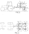
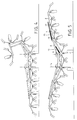
- the tedder shown in Figures 1 to 5 is pulled by a tractor and is equipped with eight tine rotors. It has a central chassis, which essentially consists of a side member 1 and a cross member 2 and is supported at all times by two transport wheels 3 on the ground.
- the transport wheels 3 are adjustable in height, as shown in FIG. 2.
- Each wheel sits on a rocker 4 which can be pivoted up and down by means of a single-acting hydraulic cylinder 5.
- Two tine rotors are mounted on the cross member 2 of the middle frame.
- the cross member 2 is adjoined on both sides by an inner arm 6, a middle arm 7 and an outer arm 8. They are connected to each other by horizontal-axis joints 9, 10 and 11 and can therefore be in one vertical plane can be pivoted.
- Another pair of single-acting hydraulic cylinders 12 is used to swing the inner arms 6 up about the joints 9 (FIG. 5).
- the outer arms 8 are connected to one another via the middle arms 7 by double-acting hydraulic cylinders 13. This makes it possible to raise the middle arms 7 above the vertical by retracting the piston rods of these cylinders 13 and to fold the outer arms 8 inwards, as shown in FIG. 4.
- the inner arms 6 are also horizontally pivotable by means of a joint with a vertical axis 14 on the cross member 2. This is used in the transport position. If the arms with their attached tine rotors according to FIG. 4, right side, are pivoted up or folded inwards, the inner arms 6 can be swiveled horizontally forward into the position according to FIGS. 2 and 3. The drive takes place with the help of two double-acting hydraulic cylinders 15a and 15b (Fig. 1). The inner arms 6 come to rest with their forward-facing ends on cross supports 16 (FIG. 3) which are fastened to the longitudinal beam 1.
- the right cylinder 15a is a little longer than the left 15b in order to be able to pivot the right arms backwards beyond the 90 ° transverse position shown in solid lines in FIG. 1. This position serves for trench clearing and is shown in dash-dot lines in FIG. 1.
- the additional swivel angle is about 20 °. This ensures that the hay thrown from the outermost tine top is not thrown beyond the width of the machine.
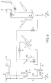
- the left half of the diagram shows the double-acting hydraulic system with the two cylinders 13 for the outer arms and the two cylinders 15a and 15b of different lengths for the horizontal pivoting movement of the inner arms 6.
- This double-acting system is fed from the double-acting hydraulic connections D of the tractor, which can be controlled by means of an adjusting lever 17.
- the lever has three positions. In one position, one connecting line 18 is under pressure and the other connecting line 19 is depressurized to return. In the middle position both connecting lines are closed (neutral position) and in the third position the connecting line 19 is under pressure and the connecting line 18 is depressurized.
- the right half of the picture shows the single-acting hydraulic system which is connected to the single-acting connection E of the tractor.
- the single-acting hydraulic system contains the two cylinders 12 for swiveling up the inner arms 6 and the two cylinders 5 for height adjustment of the undercarriage. Both systems are connected to one another via a check valve 21. It is switched on so that it opens from the connecting line 19 of the double-acting system to the connecting line of the single-acting system.
- the double-acting cylinders 13 and 15 are connected in parallel.
- a check valve 22 is arranged in the connecting line 18 after the branch to the cylinders 15. It is operated depending on the position of the inner arms 6 and can, for example, on Longitudinal beam 1 is fastened and connected in an articulated manner to one of the two arms 6 via a coupling rod 23.
- This arrangement acts in such a way that the connecting line 18 is blocked when the arms 6 are pivoted forward in the transport position.
- the check valve 22 only opens when these arms 6 have moved clearly out of the transport position and are almost in the transverse position.
- a check valve 24 is arranged in the line which branches off from the connecting line 18 and leads to the cylinders 15a and 15b. It is normally held in the locked position by a spring 25 and can be opened by pulling on a rope 26. Thus, the cylinders 15a and 15b cannot be operated with the adjusting lever 17 alone. Rather, it is additionally necessary to pull the rope 26.
- a hydraulic blocking block 27 is connected upstream and finally in the parallel branches, which contain the cylinders 15a and 15b, each a check valve 28 or 29 is arranged.
- the circuit is in opposite directions so that the right cylinder 15a leads when the piston rods are retracted and the left cylinder 15b leads when the piston rods are ejected. The purpose of this measure has already been explained in the introduction.
- the cylinder pairs 5 and 12 receive the pressure oil via a flow divider 30, so that the respective cylinders make the same path on both sides.
- the device described works as follows: It is assumed that the farmer has just finished working in the field.
- the three arms 6, 7 and 8 on either side of the tedder stand in the extended working position according to FIG. 1.
- the feeler wheels of all tine rotors have ground contact, as shown in FIG. 4 on the left side.
- the adjusting lever 20 of the single-acting connection E is briefly set to “lower”. This causes the arms to drop on the supports. As a result of the non-return throttle 31, the midframe 1, 2 drops much more slowly, i. H. only by an insignificant amount.
- the locking block 27 holds the cylinders in the position reached.
- the shut-off valve 22 has opened, so that the double-acting cylinders 13 now extend automatically and bring the arms into their extended position.
- the control lever 17 is brought into the "neutral position".
- the adjusting lever 20 is set to "lower” so that the undercarriage reaches its lowest position and the cylinders 12, like the cylinders 13, assume a floating position in which the feeler wheels of the individual tine gyroscope get in contact with the ground and also adapt to the ground during operation.
- control lever 20 To turn at the end of the field, only the control lever 20 is placed on “lifting", so that both the chassis and the inner arms 6 are swung up, the extent of these movements being at the discretion of the tractor driver. He will make sure that the feeler wheels and all rotary tines are lifted off the ground, as shown in Fig. 5. After turning, the control lever 20 is put back on "lowering".
- the arms on the right side of the tedder can be pivoted further to the end position of the cylinder 15a to the rear, so starting from the extended position according to FIG Pressure set and the rope 26 pulled.
- the cylinder 15a then runs into its end position. Then the cable 26 can be released and the adjusting lever 17 can be reset to "neutral".
Landscapes
- Life Sciences & Earth Sciences (AREA)
- Environmental Sciences (AREA)
- Lifting Devices For Agricultural Implements (AREA)
- Forklifts And Lifting Vehicles (AREA)
- Automobile Manufacture Line, Endless Track Vehicle, Trailer (AREA)
Applications Claiming Priority (2)
| Application Number | Priority Date | Filing Date | Title |
|---|---|---|---|
| DE19618263 | 1996-05-07 | ||
| DE19618263A DE19618263A1 (de) | 1996-05-07 | 1996-05-07 | Vorrichtung zum Schwenken der Tragarme von Vielkreisel-Heumaschinen |
Publications (2)
| Publication Number | Publication Date |
|---|---|
| EP0806133A1 true EP0806133A1 (fr) | 1997-11-12 |
| EP0806133B1 EP0806133B1 (fr) | 2001-08-16 |
Family
ID=7793564
Family Applications (1)
| Application Number | Title | Priority Date | Filing Date |
|---|---|---|---|
| EP97105893A Expired - Lifetime EP0806133B1 (fr) | 1996-05-07 | 1997-04-10 | Dispositif pour pivoter les roues râteleuses d'une machine de fenaison |
Country Status (3)
| Country | Link |
|---|---|
| EP (1) | EP0806133B1 (fr) |
| AT (1) | ATE204118T1 (fr) |
| DE (2) | DE19618263A1 (fr) |
Cited By (8)
| Publication number | Priority date | Publication date | Assignee | Title |
|---|---|---|---|---|
| EP0848900A1 (fr) * | 1994-01-28 | 1998-06-24 | Maasland N.V. | Machine de fenaison |
| EP0937383A1 (fr) * | 1998-02-23 | 1999-08-25 | Maschinenfabrik Bernard Krone GmbH | Machine de fenaison |
| EP0951818A1 (fr) | 1998-04-24 | 1999-10-27 | Kverneland Gottmadingen GmbH & Co. KG | Machine de fenaison |
| FR2787286A1 (fr) * | 1998-12-18 | 2000-06-23 | Kuhn Sa | Machine de fenaison a commande hydraulique combinee pour le relevage des troncons lateraux ou l'orientation des roues |
| EP1050205A1 (fr) * | 1999-05-05 | 2000-11-08 | Claas Saulgau Gmbh | Machine de fenaison |
| FR2890526A1 (fr) * | 2005-09-09 | 2007-03-16 | Kuhn Sa Sa | Machine de fenaison avec des structures laterales repliables |
| FR2901661A1 (fr) * | 2006-05-30 | 2007-12-07 | Poettinger Alois Maschf | Machine agricole,notamment faneuse a toupies comprenant des moyens de blocage affectes au verin de relevage |
| FR3082389A1 (fr) * | 2018-06-18 | 2019-12-20 | Kuhn S.A. | Machine de fenaison avec largeur de projection controlee |
Citations (7)
| Publication number | Priority date | Publication date | Assignee | Title |
|---|---|---|---|---|
| EP0165638A1 (fr) * | 1984-06-12 | 1985-12-27 | P.J. Zweegers en Zonen Landbouwmachinefabriek B.V. | Appareil pour le traitement de végétaux se trouvant sur le sol |
| DE8807054U1 (de) * | 1988-05-30 | 1989-06-22 | Alois Pöttinger Landmaschinen-Gesellschaft mbH, 8900 Augsburg | Heuwerbungsmaschine |
| DE9010179U1 (de) * | 1990-07-04 | 1990-09-20 | H. Niemeyer Söhne GmbH & Co KG, 4446 Hörstel | Heuwerbungsmaschine |
| EP0391093A1 (fr) * | 1989-04-07 | 1990-10-10 | Claas Saulgau Gmbh | Machine agricole |
| DE4128585A1 (de) * | 1991-08-28 | 1993-03-04 | Poettinger Alois Landmasch | Heuwerbungsmaschine |
| EP0628240A1 (fr) * | 1993-06-07 | 1994-12-14 | Maasland N.V. | Machine de fenaison |
| EP0753247A1 (fr) * | 1995-07-12 | 1997-01-15 | Claas Saulgau Gmbh | Machine de travail agricole, notamment faneuse à plusieurs rotors |
Family Cites Families (4)
| Publication number | Priority date | Publication date | Assignee | Title |
|---|---|---|---|---|
| DE2220114A1 (de) * | 1972-04-25 | 1973-10-31 | Jacques Roby Dr Schlittler | Heuwerbungsmaschine |
| DE8810667U1 (de) * | 1988-08-24 | 1990-01-04 | Alois Pöttinger Landmaschinen-Gesellschaft mbH, 8900 Augsburg | Heuwerbungsmaschine |
| DE4023092C2 (de) * | 1990-07-20 | 1998-07-23 | Claas Saulgau Gmbh | Landwirtschaftliche Arbeitsmaschine |
| DE4322263C5 (de) * | 1992-07-31 | 2009-04-23 | Claas Saulgau Gmbh | Verfahren zur Vorbereitung eines auf einer Bodenfläche fahrenden Arbeitsfahrzeuges mit einem Arbeitsgerät für den Straßenbetrieb und Arbeitsgerät zur Anordnung an einem solchen Arbeitsfahrzeug |
-
1996
- 1996-05-07 DE DE19618263A patent/DE19618263A1/de not_active Withdrawn
-
1997
- 1997-04-10 AT AT97105893T patent/ATE204118T1/de not_active IP Right Cessation
- 1997-04-10 EP EP97105893A patent/EP0806133B1/fr not_active Expired - Lifetime
- 1997-04-10 DE DE59704268T patent/DE59704268D1/de not_active Expired - Lifetime
Patent Citations (7)
| Publication number | Priority date | Publication date | Assignee | Title |
|---|---|---|---|---|
| EP0165638A1 (fr) * | 1984-06-12 | 1985-12-27 | P.J. Zweegers en Zonen Landbouwmachinefabriek B.V. | Appareil pour le traitement de végétaux se trouvant sur le sol |
| DE8807054U1 (de) * | 1988-05-30 | 1989-06-22 | Alois Pöttinger Landmaschinen-Gesellschaft mbH, 8900 Augsburg | Heuwerbungsmaschine |
| EP0391093A1 (fr) * | 1989-04-07 | 1990-10-10 | Claas Saulgau Gmbh | Machine agricole |
| DE9010179U1 (de) * | 1990-07-04 | 1990-09-20 | H. Niemeyer Söhne GmbH & Co KG, 4446 Hörstel | Heuwerbungsmaschine |
| DE4128585A1 (de) * | 1991-08-28 | 1993-03-04 | Poettinger Alois Landmasch | Heuwerbungsmaschine |
| EP0628240A1 (fr) * | 1993-06-07 | 1994-12-14 | Maasland N.V. | Machine de fenaison |
| EP0753247A1 (fr) * | 1995-07-12 | 1997-01-15 | Claas Saulgau Gmbh | Machine de travail agricole, notamment faneuse à plusieurs rotors |
Cited By (10)
| Publication number | Priority date | Publication date | Assignee | Title |
|---|---|---|---|---|
| EP0848900A1 (fr) * | 1994-01-28 | 1998-06-24 | Maasland N.V. | Machine de fenaison |
| EP0937383A1 (fr) * | 1998-02-23 | 1999-08-25 | Maschinenfabrik Bernard Krone GmbH | Machine de fenaison |
| EP0951818A1 (fr) | 1998-04-24 | 1999-10-27 | Kverneland Gottmadingen GmbH & Co. KG | Machine de fenaison |
| FR2787286A1 (fr) * | 1998-12-18 | 2000-06-23 | Kuhn Sa | Machine de fenaison a commande hydraulique combinee pour le relevage des troncons lateraux ou l'orientation des roues |
| EP1013161A1 (fr) * | 1998-12-18 | 2000-06-28 | Kuhn S.A. | Machine de fenaison |
| EP1050205A1 (fr) * | 1999-05-05 | 2000-11-08 | Claas Saulgau Gmbh | Machine de fenaison |
| FR2890526A1 (fr) * | 2005-09-09 | 2007-03-16 | Kuhn Sa Sa | Machine de fenaison avec des structures laterales repliables |
| WO2007028926A3 (fr) * | 2005-09-09 | 2007-05-03 | Kuhn Sa | Machine de fenaison avec des structures laterales repliables |
| FR2901661A1 (fr) * | 2006-05-30 | 2007-12-07 | Poettinger Alois Maschf | Machine agricole,notamment faneuse a toupies comprenant des moyens de blocage affectes au verin de relevage |
| FR3082389A1 (fr) * | 2018-06-18 | 2019-12-20 | Kuhn S.A. | Machine de fenaison avec largeur de projection controlee |
Also Published As
| Publication number | Publication date |
|---|---|
| DE59704268D1 (de) | 2001-09-20 |
| DE19618263A1 (de) | 1997-11-13 |
| EP0806133B1 (fr) | 2001-08-16 |
| ATE204118T1 (de) | 2001-09-15 |
Similar Documents
| Publication | Publication Date | Title |
|---|---|---|
| DE2737053C3 (de) | Landwirtschaftlich nutzbares Arbeitsgerät | |
| DE69013175T2 (de) | Flugzeugtraktor. | |
| EP0097347B1 (fr) | Châssis porte-outils | |
| DE2846470C2 (de) | Bewegliches Hubgerät | |
| EP0439837B1 (fr) | Chariot à fourche | |
| DE602005003560T2 (de) | Diagnosegerät für eine Auflieger-Anhängerkupplung eines Fahrzeugs | |
| EP1163830B1 (fr) | Appareil agricole tracté | |
| EP0806133B1 (fr) | Dispositif pour pivoter les roues râteleuses d'une machine de fenaison | |
| EP0753247A1 (fr) | Machine de travail agricole, notamment faneuse à plusieurs rotors | |
| DE2133779A1 (de) | Tragfahrzeug zur Aufnahme eines Gerätes, insbesondere eines Erntebergungsgerätes | |
| EP1142467A1 (fr) | Dispositif de cueillette de céréales | |
| DE4322263C5 (de) | Verfahren zur Vorbereitung eines auf einer Bodenfläche fahrenden Arbeitsfahrzeuges mit einem Arbeitsgerät für den Straßenbetrieb und Arbeitsgerät zur Anordnung an einem solchen Arbeitsfahrzeug | |
| WO1993019974A1 (fr) | Mecanisme de roulement a ecartement variable | |
| DE9312222U1 (de) | Heuwerbungsmaschine | |
| EP0564687B1 (fr) | Dispositif de remorquage | |
| EP0289864B1 (fr) | Machine de fenaison | |
| EP1062859A2 (fr) | Presse-botteleuse | |
| DE3218525C2 (de) | Böschungsmähgerät | |
| DE1932040A1 (de) | Gewichtsuebertragungskupplung | |
| DE2263117A1 (de) | Greifgleitschlepper mit selbstzentrierender greiferbefestigung | |
| DE3419205C2 (de) | Gleisbaumaschine zum Verlegen und Ausbauen von montierten Gleisabschnitten oder Gleisverbindungen | |
| DE10120845B4 (de) | Hydromechanische Steuerungsvorrichtung für eine mehrteilige landwirtschaftliche Arbeitsmaschine | |
| EP1616471A2 (fr) | Dispositif de commande hydraulique pour machine agricole | |
| DE8716698U1 (de) | Heuwerbungsmaschine | |
| EP1830006B1 (fr) | Machine de travaux de construction et procédé pour la preparation du transport de cette machine |
Legal Events
| Date | Code | Title | Description |
|---|---|---|---|
| PUAI | Public reference made under article 153(3) epc to a published international application that has entered the european phase |
Free format text: ORIGINAL CODE: 0009012 |
|
| 17P | Request for examination filed |
Effective date: 19970911 |
|
| AK | Designated contracting states |
Kind code of ref document: A1 Designated state(s): AT DE FR NL |
|
| D17P | Request for examination filed (deleted) | ||
| R17P | Request for examination filed (corrected) |
Effective date: 19980512 |
|
| 17Q | First examination report despatched |
Effective date: 20000228 |
|
| GRAG | Despatch of communication of intention to grant |
Free format text: ORIGINAL CODE: EPIDOS AGRA |
|
| GRAG | Despatch of communication of intention to grant |
Free format text: ORIGINAL CODE: EPIDOS AGRA |
|
| GRAH | Despatch of communication of intention to grant a patent |
Free format text: ORIGINAL CODE: EPIDOS IGRA |
|
| GRAH | Despatch of communication of intention to grant a patent |
Free format text: ORIGINAL CODE: EPIDOS IGRA |
|
| GRAA | (expected) grant |
Free format text: ORIGINAL CODE: 0009210 |
|
| AK | Designated contracting states |
Kind code of ref document: B1 Designated state(s): AT DE FR NL |
|
| REF | Corresponds to: |
Ref document number: 204118 Country of ref document: AT Date of ref document: 20010915 Kind code of ref document: T |
|
| REF | Corresponds to: |
Ref document number: 59704268 Country of ref document: DE Date of ref document: 20010920 |
|
| ET | Fr: translation filed | ||
| PLBE | No opposition filed within time limit |
Free format text: ORIGINAL CODE: 0009261 |
|
| STAA | Information on the status of an ep patent application or granted ep patent |
Free format text: STATUS: NO OPPOSITION FILED WITHIN TIME LIMIT |
|
| 26N | No opposition filed | ||
| PGFP | Annual fee paid to national office [announced via postgrant information from national office to epo] |
Ref country code: NL Payment date: 20090415 Year of fee payment: 13 Ref country code: FR Payment date: 20090414 Year of fee payment: 13 Ref country code: DE Payment date: 20080903 Year of fee payment: 13 Ref country code: AT Payment date: 20090416 Year of fee payment: 13 |
|
| PG25 | Lapsed in a contracting state [announced via postgrant information from national office to epo] |
Ref country code: DE Free format text: LAPSE BECAUSE OF THE APPLICANT RENOUNCES Effective date: 20100203 |
|
| REG | Reference to a national code |
Ref country code: NL Ref legal event code: V1 Effective date: 20101101 |
|
| REG | Reference to a national code |
Ref country code: FR Ref legal event code: ST Effective date: 20101230 |
|
| PG25 | Lapsed in a contracting state [announced via postgrant information from national office to epo] |
Ref country code: NL Free format text: LAPSE BECAUSE OF NON-PAYMENT OF DUE FEES Effective date: 20101101 Ref country code: AT Free format text: LAPSE BECAUSE OF NON-PAYMENT OF DUE FEES Effective date: 20100410 |
|
| PG25 | Lapsed in a contracting state [announced via postgrant information from national office to epo] |
Ref country code: FR Free format text: LAPSE BECAUSE OF NON-PAYMENT OF DUE FEES Effective date: 20100430 |