EP0753352A2 - Pulvérisateur comprenant une pompe à pré-compression avec réglage de la quantité - Google Patents
Pulvérisateur comprenant une pompe à pré-compression avec réglage de la quantité Download PDFInfo
- Publication number
- EP0753352A2 EP0753352A2 EP96201935A EP96201935A EP0753352A2 EP 0753352 A2 EP0753352 A2 EP 0753352A2 EP 96201935 A EP96201935 A EP 96201935A EP 96201935 A EP96201935 A EP 96201935A EP 0753352 A2 EP0753352 A2 EP 0753352A2
- Authority
- EP
- European Patent Office
- Prior art keywords
- stem
- fluid
- piece
- collar
- designed
- Prior art date
- Legal status (The legal status is an assumption and is not a legal conclusion. Google has not performed a legal analysis and makes no representation as to the accuracy of the status listed.)
- Granted
Links
- 239000012530 fluid Substances 0.000 title claims abstract description 52
- 230000006835 compression Effects 0.000 title claims description 8
- 238000007906 compression Methods 0.000 title claims description 8
- 238000007789 sealing Methods 0.000 claims abstract description 5
- 244000273618 Sphenoclea zeylanica Species 0.000 claims abstract description 3
- 230000002441 reversible effect Effects 0.000 claims description 2
- 238000006073 displacement reaction Methods 0.000 claims 1
- 230000001105 regulatory effect Effects 0.000 description 3
- 238000013461 design Methods 0.000 description 2
- 230000000630 rising effect Effects 0.000 description 2
- 238000000926 separation method Methods 0.000 description 2
- 230000006978 adaptation Effects 0.000 description 1
- 238000004891 communication Methods 0.000 description 1
- 230000008878 coupling Effects 0.000 description 1
- 238000010168 coupling process Methods 0.000 description 1
- 238000005859 coupling reaction Methods 0.000 description 1
- 238000007667 floating Methods 0.000 description 1
- 238000003780 insertion Methods 0.000 description 1
- 230000037431 insertion Effects 0.000 description 1
- 230000001788 irregular Effects 0.000 description 1
- 238000004519 manufacturing process Methods 0.000 description 1
- 238000012986 modification Methods 0.000 description 1
- 230000004048 modification Effects 0.000 description 1
- 239000002304 perfume Substances 0.000 description 1
- 238000005086 pumping Methods 0.000 description 1
- 230000000717 retained effect Effects 0.000 description 1
- 238000013519 translation Methods 0.000 description 1
Images

Classifications
-
- B—PERFORMING OPERATIONS; TRANSPORTING
- B05—SPRAYING OR ATOMISING IN GENERAL; APPLYING FLUENT MATERIALS TO SURFACES, IN GENERAL
- B05B—SPRAYING APPARATUS; ATOMISING APPARATUS; NOZZLES
- B05B11/00—Single-unit hand-held apparatus in which flow of contents is produced by the muscular force of the operator at the moment of use
- B05B11/01—Single-unit hand-held apparatus in which flow of contents is produced by the muscular force of the operator at the moment of use characterised by the means producing the flow
- B05B11/10—Pump arrangements for transferring the contents from the container to a pump chamber by a sucking effect and forcing the contents out through the dispensing nozzle
- B05B11/1001—Piston pumps
- B05B11/1005—Piston pumps with means for adjusting or modifying pump stroke
- B05B11/1007—Piston pumps with means for adjusting or modifying pump stroke by adjusting or modifying the pump end-of-sucking-stroke position
-
- B—PERFORMING OPERATIONS; TRANSPORTING
- B05—SPRAYING OR ATOMISING IN GENERAL; APPLYING FLUENT MATERIALS TO SURFACES, IN GENERAL
- B05B—SPRAYING APPARATUS; ATOMISING APPARATUS; NOZZLES
- B05B11/00—Single-unit hand-held apparatus in which flow of contents is produced by the muscular force of the operator at the moment of use
- B05B11/01—Single-unit hand-held apparatus in which flow of contents is produced by the muscular force of the operator at the moment of use characterised by the means producing the flow
- B05B11/10—Pump arrangements for transferring the contents from the container to a pump chamber by a sucking effect and forcing the contents out through the dispensing nozzle
- B05B11/1001—Piston pumps
- B05B11/1023—Piston pumps having an outlet valve opened by deformation or displacement of the piston relative to its actuating stem
- B05B11/1025—Piston pumps having an outlet valve opened by deformation or displacement of the piston relative to its actuating stem a spring urging the outlet valve in its closed position
Definitions
- the present invention relates to a fluid delivery and atomizing device which is provided with means for regulation of the quantity of fluid to be delivered during each operating cycle and with interchangeable parts for regulation of the aperture of the fluid delivery duct depending on the density of the fluid itself.
- pre-compression pumps are known, namely of the type which are provided with an obturator movable against the action of a suitably calibrated spring; said obturator covers a hole through which the fluid flows towards the delivery cap and is lifted from this hole only after being subjected by the user to a pressure corresponding to the force sufficient to overcome the opposing action exerted by the said spring on the obturator itself.
- the fluid flow ducts are of considerable length and have a small cross-section and are therefore the cause - in particular when the pump is used for high-density fluids - of pressure drops during flowing of the fluid, resulting in irregular delivery and the need to overdimension the load of the pre-compression spring, with the consequent need for a considerable operating force on the part of the user.
- the technical problem which is posed, therefore, is that of providing a device for delivering and atomizing fluids contained in a storage container, which allows the quantity of fluid delivered to be varied in a simple and economic manner without the need for modifying correspondingly the dimensions of each individual part forming the device.
- a fluid delivery and atomizing device comprising a hollow body and a hollow stem which are coaxially movable with respect to the said hollow body against the thrusting action of first and second resilient elements, in which the bottom end of said second resilient means is in abutment with an annular gasket radially arranged between the hollow body and stem and axially movable relative to the latter, said device being designed such that said stem is provided with a collar on which the top end of said second resilient means act and the axial dimension of which is designed to determine the volume of fluid which can be delivered during each operating cycle of the device, there also being provided an interchangeable base-piece which can be reversibly fitted to the bottom end of the stem and which cooperates with the movable annular gasket in order to seal off the fluid delivery duct at the end of the compression stroke of the stem.
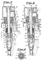
- the delivery device comprises a hollow substantially cylindrical body 1 on the bottom of which there is formed a seat la housing a floating sphere 1b designed to function as a one-way valve for the passage of a fluid "F" contained in a bottle 2 inside which the said hollow body is inserted and sealingly fastened via suitable means described in detail below.
- the hollow body 1 has arranged inside it, coaxially therewith, a stem 3 which in turn is internally hollow and slidable in an axial direction relative to hollow body 1 itself.
- the top end 3a of the stem 3 projects in an axial direction beyond the hollow body so as to support a delivery cap 4 provided with a radial hole 4a for supplying the fluid to a micronization chamber 4b from where the fluid emerges suitably atomized for the application.
- the opposite bottom end 3b of the stem 3 has reversibly fitted to it a base-piece 5 which is provided on its internal surface with shoulders 5a ( Figures 1 and 4) designed to engage with a corresponding annular projection 3c of the stem 3.
- the inclined surface of the said shoulders 5a and of the annular projection 3c allows easy insertion of the base-piece 5 which in this way is stably coupled to the stem 3.
- the said base-piece 5 although it is provided with internal openings for passage of the fluid is, however, closed externally, avoiding the need for arranging sealing elements in between with obvious simplification of the design of the parts to be combined.
- the external surface of the base-piece 5 has formed on it a support surface 5b with, acting against it, the top end of a spring 6 which reacts against an associated seat of the hollow body 1 so as to keep the base-piece itself, and hence the stem 3, raised with respect to an annular abutment shoulder lc which can be fitted onto the internal surface of the hollow body 1.
- the stem 3 has formed in its approximately middle part ( Figures 1 and 2) an annular rib 3d designed to engage with corresponding concave seats 7a formed on the internal surface of a sliding piece 7 coaxially mounted on the stem 3.
- the upper surface of the sliding piece 7 has formed on it an annular seat 7b designed to enter into contact with an end-of-travel element 8a of a gasket 8 arranged between a stopper 9 with an internal thread 9a designed to be coupled with the threading 2a of the neck 2b of the container so as to sealingly fasten the delivery device to the container itself.
- an annular gasket 10 provided with a vertical tongue 10b designed to come into contact and form a seal with the top edge 5c of the base-piece 5; in this way the gasket 10, the body 1 and the base-piece 5 define a pressure chamber 11 consisting of an upper part lla of substantially cylindrical shape and a lower part llb of substantially frustoconical shape, through which the fluid F is drawn up for delivery, as will be described below.
- Said gaskets 10 and collar 7 have axially arranged between them a spring 12 designed to cause the pre-compression of the device since, only when the thrusting action exerted by the user on the delivery cap 4 has compressed the spring 12, does delivery of the fluid externally occur.
- said cavities 7a of the sliding piece 7 and said rib 3d of the stem3could also be arranged inclined in accordance with the pitch of a thread/nut screw fastening system which can be operated by means of rotation of the delivery cap 4, in this case resilient relief-type elements being provided in order to prevent undesired rotation of the sliding piece 7, but instead allow axial translation thereof following actuation by the user and the springs 6 and 12.
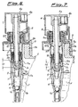
- Figure 3 shows a simplified example of embodiment of the device according to the invention in which the stem 3 has a fixed collar 107 with a top surface having in it an incision so as to form an annular seat 107b designed to come into contact with the said end-of-travel element 8a of the gasket 8.
- the height of the said collar 107 determines once again the different height (H1, H2) of the upper part lla of the chamber 11 and hence the quantity of fluid to be delivered.
- the delivery device After ascertaining the density of the fluid and establishing the quantity of fluid to be delivered for each pumping cycle and having consequently calibrated the height of the collar 107 (or, in the embodiment of Figure 1, axially translated the sliding piece 7 into a suitable position), as well as fitting to the stem 3 a base-piece 5 of suitable external diameter, the delivery device is fitted to the bottle 2 by means of the stopper 9.
- the cap 4 is pressed, causing the descent of the stem 3 inside the hollow body 1, since the fluid F present inside the chamber 11 cannot be compressed and cannot return into the container 2, being retained by the sphere 1b, and constitutes an obstacle to descent of the gasket 10 which remains immobile until the spring 12 is compressed and the base-piece 5 is consequently separated from the gasket 10 itself.
- This separation causes opening of the chamber lla and consequent rising up again of the fluid F through the internal cavity of the stem 3 as far as the delivery cap 4 inside which it is atomized for delivery.
- the spring 12 reacts against the collar 7, which at this point is at a standstill, and begins exerting its thrusting action on the annular gasket 10, pushing it downwards so that the lug 10b comes back into contact with the top edge 5c of the base-piece 5, closing again the chamber 11 and consequently interrupting delivery.
- the spring 6 is allowed to push again upwards the base-piece 5 and hence the gasket 10 and the stem 3 which move simultaneously causing a drop in pressure inside the chamber 11 itself which raises the sphere 1b, opening up the bottom of the body 1 and causing fluid F to be drawn back inside the chamber 11 which in this way is filled again for subsequent delivery.
- the fluid F rising back up from the container to the chamber 11, causes a drop in pressure inside the container which is balanced by the entry of air drawn in from outside.
- the working stroke of the stem 3 with respect to the hollow body 1, and hence the volume of fluid which can be delivered during each cycle of the pump is substantially determined by the height in the axial direction of the said collar 107 which, as illustrated in Figure 7, may be made with a much greater height, thus resulting in a reduction in the compression stroke and hence a reduction in the volume of fluid delivered per cycle.
- the stroke of the stem is determined by the more or less lowered position of the sliding-piece 7.
- the simplified version of the device according to the invention may prove suitable for those mass production operations where a corresponding variation in the forming mould has an essentially negligible impact on the final unit cost
- the realization of the device with a sliding piece which allows a variation in the quantity of fluid which can be delivered, without the need for variations in the moulds, but by means of a simple positional adjustment, will certainly prove convenient owing to the series of small number of parts.
- reversible coupling of the base-piece to the stem also allows the aperture of the fluid flow passage through the chamber to be varied, a requirement which is of particular importance when there is an increase in the density of the fluid to be delivered.
Landscapes
- Containers And Packaging Bodies Having A Special Means To Remove Contents (AREA)
- Nozzles (AREA)
- Catching Or Destruction (AREA)
Applications Claiming Priority (2)
| Application Number | Priority Date | Filing Date | Title |
|---|---|---|---|
| ITMI950505U | 1995-07-14 | ||
| IT1995MI000505U IT237035Y1 (it) | 1995-07-14 | 1995-07-14 | Dispositivo erogatore e nebulizzatore di fluidi comprendente mezziper la regolazione della quantita' di fluido da erogare ad ogni |
Publications (3)
| Publication Number | Publication Date |
|---|---|
| EP0753352A2 true EP0753352A2 (fr) | 1997-01-15 |
| EP0753352A3 EP0753352A3 (fr) | 1997-06-25 |
| EP0753352B1 EP0753352B1 (fr) | 2002-02-13 |
Family
ID=11370909
Family Applications (1)
| Application Number | Title | Priority Date | Filing Date |
|---|---|---|---|
| EP96201935A Expired - Lifetime EP0753352B1 (fr) | 1995-07-14 | 1996-07-10 | Pulvérisateur comprenant une pompe à pré-compression avec réglage de la quantité |
Country Status (3)
| Country | Link |
|---|---|
| EP (1) | EP0753352B1 (fr) |
| DE (1) | DE69619169D1 (fr) |
| IT (1) | IT237035Y1 (fr) |
Cited By (1)
| Publication number | Priority date | Publication date | Assignee | Title |
|---|---|---|---|---|
| EP2067426A3 (fr) * | 2007-12-07 | 2017-11-01 | Gotohti.com Inc. | Distributeur de mousse à fente angulaire |
Family Cites Families (4)
| Publication number | Priority date | Publication date | Assignee | Title |
|---|---|---|---|---|
| IT211917Z2 (it) * | 1987-07-30 | 1989-05-25 | Elettro Plastica Srl | Pompa di erogazione applicabile a contenitori di fluidi. |
| WO1993009879A1 (fr) * | 1991-11-15 | 1993-05-27 | Nabil Ghattas Sarraf | Appareil distributeur de fluide |
| FR2718372B1 (fr) * | 1994-04-08 | 1996-06-28 | Sofab | Dispensateur de produits fluides. |
| SI9600118A (en) * | 1995-04-13 | 1996-10-31 | Monturas Sa | Precompression pump sprayer |
-
1995
- 1995-07-14 IT IT1995MI000505U patent/IT237035Y1/it active IP Right Grant
-
1996
- 1996-07-10 DE DE69619169T patent/DE69619169D1/de not_active Expired - Lifetime
- 1996-07-10 EP EP96201935A patent/EP0753352B1/fr not_active Expired - Lifetime
Cited By (1)
| Publication number | Priority date | Publication date | Assignee | Title |
|---|---|---|---|---|
| EP2067426A3 (fr) * | 2007-12-07 | 2017-11-01 | Gotohti.com Inc. | Distributeur de mousse à fente angulaire |
Also Published As
| Publication number | Publication date |
|---|---|
| EP0753352B1 (fr) | 2002-02-13 |
| DE69619169D1 (de) | 2002-03-21 |
| EP0753352A3 (fr) | 1997-06-25 |
| IT237035Y1 (it) | 2000-08-31 |
| ITMI950505V0 (it) | 1995-07-14 |
| ITMI950505U1 (it) | 1997-01-14 |
Similar Documents
| Publication | Publication Date | Title |
|---|---|---|
| US4228931A (en) | Manually operated pump for dispensing micronized liquids at a predetermined pressure | |
| US4434916A (en) | Manually operated liquid dispensing pump | |
| US4735347A (en) | Single puff atomizing pump dispenser | |
| US5803318A (en) | Precompression pump | |
| US4201317A (en) | Finger actuated pump assembly | |
| EP0625075B1 (fr) | Ensemble pompe de pulverisation de liquide par des orifices multiples selon differents profils de distribution avec reglage automatique de la course maximale de la pompe pour chaque schema | |
| US5806721A (en) | Container mounted pump dispenser with back suction | |
| US8206136B2 (en) | System of diaphragm and co-acting part | |
| US4607765A (en) | Manually operated pump for the delivery under pressure of liquid substances | |
| US5301852A (en) | Manually operated pump for dispensing liquid or creamy substances at a predetermined constant pressure | |
| EP3078313A1 (fr) | Dispositif de pompage et ses procédés de fabrication | |
| JPH02246976A (ja) | 液体又はクリーム状の物質を小滴状に分与する分与装置及びこの分与装置を包含する分与組立体 | |
| EP1266696A1 (fr) | Pompe à soufflet pour la distribution de mélanges gaz-liquide | |
| JPH081171B2 (ja) | 計量分配ポンプ | |
| CZ288430B6 (en) | Precompression pump sprayer | |
| EP0484615B1 (fr) | Dispositif de pompage manuel pour distribuer des fluides | |
| EP3261781B1 (fr) | Système d'actionnement pour un système de distribution de substance fluide | |
| CN113226567B (zh) | 用于分配液体制品的装置 | |
| JPH02127270A (ja) | 予圧縮計量ポンプ | |
| US5566865A (en) | Manual atomizing pump with adjustable dosage | |
| JP4327307B2 (ja) | 媒体ディスペンサ | |
| JPH06345115A (ja) | 液体噴霧用手動予備圧縮ポンプ | |
| GB2141184A (en) | Dispensing pump | |
| CN100354046C (zh) | 带有分配头的流体产品分配装置 | |
| US10525492B2 (en) | Molded pump for dispensing a fluid product |
Legal Events
| Date | Code | Title | Description |
|---|---|---|---|
| PUAI | Public reference made under article 153(3) epc to a published international application that has entered the european phase |
Free format text: ORIGINAL CODE: 0009012 |
|
| AK | Designated contracting states |
Kind code of ref document: A2 Designated state(s): DE ES FR GB IT |
|
| AX | Request for extension of the european patent |
Free format text: AL;LT;LV;SI |
|
| RBV | Designated contracting states (corrected) |
Designated state(s): DE ES FR GB IT |
|
| PUAL | Search report despatched |
Free format text: ORIGINAL CODE: 0009013 |
|
| AK | Designated contracting states |
Kind code of ref document: A3 Designated state(s): DE ES FR GB IT |
|
| AX | Request for extension of the european patent |
Free format text: AL;LT;LV;SI |
|
| DAX | Request for extension of the european patent (deleted) | ||
| 17P | Request for examination filed |
Effective date: 19971215 |
|
| 17Q | First examination report despatched |
Effective date: 20000718 |
|
| GRAG | Despatch of communication of intention to grant |
Free format text: ORIGINAL CODE: EPIDOS AGRA |
|
| GRAG | Despatch of communication of intention to grant |
Free format text: ORIGINAL CODE: EPIDOS AGRA |
|
| GRAH | Despatch of communication of intention to grant a patent |
Free format text: ORIGINAL CODE: EPIDOS IGRA |
|
| GRAH | Despatch of communication of intention to grant a patent |
Free format text: ORIGINAL CODE: EPIDOS IGRA |
|
| GRAA | (expected) grant |
Free format text: ORIGINAL CODE: 0009210 |
|
| REG | Reference to a national code |
Ref country code: GB Ref legal event code: IF02 |
|
| AK | Designated contracting states |
Kind code of ref document: B1 Designated state(s): DE ES FR GB IT |
|
| PG25 | Lapsed in a contracting state [announced via postgrant information from national office to epo] |
Ref country code: IT Free format text: LAPSE BECAUSE OF FAILURE TO SUBMIT A TRANSLATION OF THE DESCRIPTION OR TO PAY THE FEE WITHIN THE PRE;WARNING: LAPSES OF ITALIAN PATENTS WITH EFFECTIVE DATE BEFORE 2007 MAY HAVE OCCURRED AT ANY TIME BEFORE 2007. THE CORRECT EFFECTIVE DATE MAY BE DIFFERENT FROM THE ONE RECORDED.SCRIBED TIME-LIMIT Effective date: 20020213 Ref country code: FR Free format text: LAPSE BECAUSE OF FAILURE TO SUBMIT A TRANSLATION OF THE DESCRIPTION OR TO PAY THE FEE WITHIN THE PRESCRIBED TIME-LIMIT Effective date: 20020213 |
|
| REF | Corresponds to: |
Ref document number: 69619169 Country of ref document: DE Date of ref document: 20020321 |
|
| PG25 | Lapsed in a contracting state [announced via postgrant information from national office to epo] |
Ref country code: DE Free format text: LAPSE BECAUSE OF FAILURE TO SUBMIT A TRANSLATION OF THE DESCRIPTION OR TO PAY THE FEE WITHIN THE PRESCRIBED TIME-LIMIT Effective date: 20020514 |
|
| PG25 | Lapsed in a contracting state [announced via postgrant information from national office to epo] |
Ref country code: GB Free format text: LAPSE BECAUSE OF NON-PAYMENT OF DUE FEES Effective date: 20020710 |
|
| PG25 | Lapsed in a contracting state [announced via postgrant information from national office to epo] |
Ref country code: ES Free format text: LAPSE BECAUSE OF FAILURE TO SUBMIT A TRANSLATION OF THE DESCRIPTION OR TO PAY THE FEE WITHIN THE PRESCRIBED TIME-LIMIT Effective date: 20020829 |
|
| EN | Fr: translation not filed | ||
| PLBE | No opposition filed within time limit |
Free format text: ORIGINAL CODE: 0009261 |
|
| STAA | Information on the status of an ep patent application or granted ep patent |
Free format text: STATUS: NO OPPOSITION FILED WITHIN TIME LIMIT |
|
| 26N | No opposition filed |
Effective date: 20021114 |
|
| GBPC | Gb: european patent ceased through non-payment of renewal fee |
Effective date: 20020710 |