EP0753650B1 - Epurateur de gaz d'echappement - Google Patents
Epurateur de gaz d'echappement Download PDFInfo
- Publication number
- EP0753650B1 EP0753650B1 EP95936096A EP95936096A EP0753650B1 EP 0753650 B1 EP0753650 B1 EP 0753650B1 EP 95936096 A EP95936096 A EP 95936096A EP 95936096 A EP95936096 A EP 95936096A EP 0753650 B1 EP0753650 B1 EP 0753650B1
- Authority
- EP
- European Patent Office
- Prior art keywords
- exhaust gas
- expansion pipe
- pipe
- catalyst
- thin
- Prior art date
- Legal status (The legal status is an assumption and is not a legal conclusion. Google has not performed a legal analysis and makes no representation as to the accuracy of the status listed.)
- Expired - Lifetime
Links
Images



Classifications
-
- F—MECHANICAL ENGINEERING; LIGHTING; HEATING; WEAPONS; BLASTING
- F01—MACHINES OR ENGINES IN GENERAL; ENGINE PLANTS IN GENERAL; STEAM ENGINES
- F01N—GAS-FLOW SILENCERS OR EXHAUST APPARATUS FOR MACHINES OR ENGINES IN GENERAL; GAS-FLOW SILENCERS OR EXHAUST APPARATUS FOR INTERNAL-COMBUSTION ENGINES
- F01N13/00—Exhaust or silencing apparatus characterised by constructional features
- F01N13/08—Other arrangements or adaptations of exhaust conduits
-
- F—MECHANICAL ENGINEERING; LIGHTING; HEATING; WEAPONS; BLASTING
- F01—MACHINES OR ENGINES IN GENERAL; ENGINE PLANTS IN GENERAL; STEAM ENGINES
- F01N—GAS-FLOW SILENCERS OR EXHAUST APPARATUS FOR MACHINES OR ENGINES IN GENERAL; GAS-FLOW SILENCERS OR EXHAUST APPARATUS FOR INTERNAL-COMBUSTION ENGINES
- F01N1/00—Silencing apparatus characterised by method of silencing
- F01N1/08—Silencing apparatus characterised by method of silencing by reducing exhaust energy by throttling or whirling
-
- F—MECHANICAL ENGINEERING; LIGHTING; HEATING; WEAPONS; BLASTING
- F01—MACHINES OR ENGINES IN GENERAL; ENGINE PLANTS IN GENERAL; STEAM ENGINES
- F01N—GAS-FLOW SILENCERS OR EXHAUST APPARATUS FOR MACHINES OR ENGINES IN GENERAL; GAS-FLOW SILENCERS OR EXHAUST APPARATUS FOR INTERNAL-COMBUSTION ENGINES
- F01N1/00—Silencing apparatus characterised by method of silencing
- F01N1/08—Silencing apparatus characterised by method of silencing by reducing exhaust energy by throttling or whirling
- F01N1/084—Silencing apparatus characterised by method of silencing by reducing exhaust energy by throttling or whirling the exhaust gases flowing through the silencer two or more times longitudinally in opposite directions, e.g. using parallel or concentric tubes
-
- F—MECHANICAL ENGINEERING; LIGHTING; HEATING; WEAPONS; BLASTING
- F01—MACHINES OR ENGINES IN GENERAL; ENGINE PLANTS IN GENERAL; STEAM ENGINES
- F01N—GAS-FLOW SILENCERS OR EXHAUST APPARATUS FOR MACHINES OR ENGINES IN GENERAL; GAS-FLOW SILENCERS OR EXHAUST APPARATUS FOR INTERNAL-COMBUSTION ENGINES
- F01N13/00—Exhaust or silencing apparatus characterised by constructional features
- F01N13/009—Exhaust or silencing apparatus characterised by constructional features having two or more separate purifying devices arranged in series
-
- F—MECHANICAL ENGINEERING; LIGHTING; HEATING; WEAPONS; BLASTING
- F01—MACHINES OR ENGINES IN GENERAL; ENGINE PLANTS IN GENERAL; STEAM ENGINES
- F01N—GAS-FLOW SILENCERS OR EXHAUST APPARATUS FOR MACHINES OR ENGINES IN GENERAL; GAS-FLOW SILENCERS OR EXHAUST APPARATUS FOR INTERNAL-COMBUSTION ENGINES
- F01N13/00—Exhaust or silencing apparatus characterised by constructional features
- F01N13/009—Exhaust or silencing apparatus characterised by constructional features having two or more separate purifying devices arranged in series
- F01N13/0097—Exhaust or silencing apparatus characterised by constructional features having two or more separate purifying devices arranged in series the purifying devices are arranged in a single housing
-
- F—MECHANICAL ENGINEERING; LIGHTING; HEATING; WEAPONS; BLASTING
- F01—MACHINES OR ENGINES IN GENERAL; ENGINE PLANTS IN GENERAL; STEAM ENGINES
- F01N—GAS-FLOW SILENCERS OR EXHAUST APPARATUS FOR MACHINES OR ENGINES IN GENERAL; GAS-FLOW SILENCERS OR EXHAUST APPARATUS FOR INTERNAL-COMBUSTION ENGINES
- F01N3/00—Exhaust or silencing apparatus having means for purifying, rendering innocuous, or otherwise treating exhaust
- F01N3/08—Exhaust or silencing apparatus having means for purifying, rendering innocuous, or otherwise treating exhaust for rendering innocuous
- F01N3/10—Exhaust or silencing apparatus having means for purifying, rendering innocuous, or otherwise treating exhaust for rendering innocuous by thermal or catalytic conversion of noxious components of exhaust
- F01N3/18—Exhaust or silencing apparatus having means for purifying, rendering innocuous, or otherwise treating exhaust for rendering innocuous by thermal or catalytic conversion of noxious components of exhaust characterised by methods of operation; Control
- F01N3/20—Exhaust or silencing apparatus having means for purifying, rendering innocuous, or otherwise treating exhaust for rendering innocuous by thermal or catalytic conversion of noxious components of exhaust characterised by methods of operation; Control specially adapted for catalytic conversion
-
- F—MECHANICAL ENGINEERING; LIGHTING; HEATING; WEAPONS; BLASTING
- F01—MACHINES OR ENGINES IN GENERAL; ENGINE PLANTS IN GENERAL; STEAM ENGINES
- F01N—GAS-FLOW SILENCERS OR EXHAUST APPARATUS FOR MACHINES OR ENGINES IN GENERAL; GAS-FLOW SILENCERS OR EXHAUST APPARATUS FOR INTERNAL-COMBUSTION ENGINES
- F01N3/00—Exhaust or silencing apparatus having means for purifying, rendering innocuous, or otherwise treating exhaust
- F01N3/08—Exhaust or silencing apparatus having means for purifying, rendering innocuous, or otherwise treating exhaust for rendering innocuous
- F01N3/10—Exhaust or silencing apparatus having means for purifying, rendering innocuous, or otherwise treating exhaust for rendering innocuous by thermal or catalytic conversion of noxious components of exhaust
- F01N3/24—Exhaust or silencing apparatus having means for purifying, rendering innocuous, or otherwise treating exhaust for rendering innocuous by thermal or catalytic conversion of noxious components of exhaust characterised by constructional aspects of converting apparatus
- F01N3/28—Construction of catalytic reactors
-
- F—MECHANICAL ENGINEERING; LIGHTING; HEATING; WEAPONS; BLASTING
- F01—MACHINES OR ENGINES IN GENERAL; ENGINE PLANTS IN GENERAL; STEAM ENGINES
- F01N—GAS-FLOW SILENCERS OR EXHAUST APPARATUS FOR MACHINES OR ENGINES IN GENERAL; GAS-FLOW SILENCERS OR EXHAUST APPARATUS FOR INTERNAL-COMBUSTION ENGINES
- F01N3/00—Exhaust or silencing apparatus having means for purifying, rendering innocuous, or otherwise treating exhaust
- F01N3/08—Exhaust or silencing apparatus having means for purifying, rendering innocuous, or otherwise treating exhaust for rendering innocuous
- F01N3/10—Exhaust or silencing apparatus having means for purifying, rendering innocuous, or otherwise treating exhaust for rendering innocuous by thermal or catalytic conversion of noxious components of exhaust
- F01N3/24—Exhaust or silencing apparatus having means for purifying, rendering innocuous, or otherwise treating exhaust for rendering innocuous by thermal or catalytic conversion of noxious components of exhaust characterised by constructional aspects of converting apparatus
- F01N3/28—Construction of catalytic reactors
- F01N3/2803—Construction of catalytic reactors characterised by structure, by material or by manufacturing of catalyst support
- F01N3/2807—Metal other than sintered metal
-
- F—MECHANICAL ENGINEERING; LIGHTING; HEATING; WEAPONS; BLASTING
- F01—MACHINES OR ENGINES IN GENERAL; ENGINE PLANTS IN GENERAL; STEAM ENGINES
- F01N—GAS-FLOW SILENCERS OR EXHAUST APPARATUS FOR MACHINES OR ENGINES IN GENERAL; GAS-FLOW SILENCERS OR EXHAUST APPARATUS FOR INTERNAL-COMBUSTION ENGINES
- F01N3/00—Exhaust or silencing apparatus having means for purifying, rendering innocuous, or otherwise treating exhaust
- F01N3/08—Exhaust or silencing apparatus having means for purifying, rendering innocuous, or otherwise treating exhaust for rendering innocuous
- F01N3/10—Exhaust or silencing apparatus having means for purifying, rendering innocuous, or otherwise treating exhaust for rendering innocuous by thermal or catalytic conversion of noxious components of exhaust
- F01N3/24—Exhaust or silencing apparatus having means for purifying, rendering innocuous, or otherwise treating exhaust for rendering innocuous by thermal or catalytic conversion of noxious components of exhaust characterised by constructional aspects of converting apparatus
- F01N3/28—Construction of catalytic reactors
- F01N3/2839—Arrangements for mounting catalyst support in housing, e.g. with means for compensating thermal expansion or vibration
- F01N3/2842—Arrangements for mounting catalyst support in housing, e.g. with means for compensating thermal expansion or vibration specially adapted for monolithic supports, e.g. of honeycomb type
-
- F—MECHANICAL ENGINEERING; LIGHTING; HEATING; WEAPONS; BLASTING
- F01—MACHINES OR ENGINES IN GENERAL; ENGINE PLANTS IN GENERAL; STEAM ENGINES
- F01N—GAS-FLOW SILENCERS OR EXHAUST APPARATUS FOR MACHINES OR ENGINES IN GENERAL; GAS-FLOW SILENCERS OR EXHAUST APPARATUS FOR INTERNAL-COMBUSTION ENGINES
- F01N3/00—Exhaust or silencing apparatus having means for purifying, rendering innocuous, or otherwise treating exhaust
- F01N3/08—Exhaust or silencing apparatus having means for purifying, rendering innocuous, or otherwise treating exhaust for rendering innocuous
- F01N3/10—Exhaust or silencing apparatus having means for purifying, rendering innocuous, or otherwise treating exhaust for rendering innocuous by thermal or catalytic conversion of noxious components of exhaust
- F01N3/24—Exhaust or silencing apparatus having means for purifying, rendering innocuous, or otherwise treating exhaust for rendering innocuous by thermal or catalytic conversion of noxious components of exhaust characterised by constructional aspects of converting apparatus
- F01N3/28—Construction of catalytic reactors
- F01N3/2882—Catalytic reactors combined or associated with other devices, e.g. exhaust silencers or other exhaust purification devices
-
- F—MECHANICAL ENGINEERING; LIGHTING; HEATING; WEAPONS; BLASTING
- F01—MACHINES OR ENGINES IN GENERAL; ENGINE PLANTS IN GENERAL; STEAM ENGINES
- F01N—GAS-FLOW SILENCERS OR EXHAUST APPARATUS FOR MACHINES OR ENGINES IN GENERAL; GAS-FLOW SILENCERS OR EXHAUST APPARATUS FOR INTERNAL-COMBUSTION ENGINES
- F01N3/00—Exhaust or silencing apparatus having means for purifying, rendering innocuous, or otherwise treating exhaust
- F01N3/08—Exhaust or silencing apparatus having means for purifying, rendering innocuous, or otherwise treating exhaust for rendering innocuous
- F01N3/10—Exhaust or silencing apparatus having means for purifying, rendering innocuous, or otherwise treating exhaust for rendering innocuous by thermal or catalytic conversion of noxious components of exhaust
- F01N3/24—Exhaust or silencing apparatus having means for purifying, rendering innocuous, or otherwise treating exhaust for rendering innocuous by thermal or catalytic conversion of noxious components of exhaust characterised by constructional aspects of converting apparatus
- F01N3/28—Construction of catalytic reactors
- F01N3/2882—Catalytic reactors combined or associated with other devices, e.g. exhaust silencers or other exhaust purification devices
- F01N3/2885—Catalytic reactors combined or associated with other devices, e.g. exhaust silencers or other exhaust purification devices with exhaust silencers in a single housing
-
- F—MECHANICAL ENGINEERING; LIGHTING; HEATING; WEAPONS; BLASTING
- F01—MACHINES OR ENGINES IN GENERAL; ENGINE PLANTS IN GENERAL; STEAM ENGINES
- F01N—GAS-FLOW SILENCERS OR EXHAUST APPARATUS FOR MACHINES OR ENGINES IN GENERAL; GAS-FLOW SILENCERS OR EXHAUST APPARATUS FOR INTERNAL-COMBUSTION ENGINES
- F01N3/00—Exhaust or silencing apparatus having means for purifying, rendering innocuous, or otherwise treating exhaust
- F01N3/08—Exhaust or silencing apparatus having means for purifying, rendering innocuous, or otherwise treating exhaust for rendering innocuous
- F01N3/10—Exhaust or silencing apparatus having means for purifying, rendering innocuous, or otherwise treating exhaust for rendering innocuous by thermal or catalytic conversion of noxious components of exhaust
- F01N3/24—Exhaust or silencing apparatus having means for purifying, rendering innocuous, or otherwise treating exhaust for rendering innocuous by thermal or catalytic conversion of noxious components of exhaust characterised by constructional aspects of converting apparatus
- F01N3/30—Arrangements for supply of additional air
-
- F—MECHANICAL ENGINEERING; LIGHTING; HEATING; WEAPONS; BLASTING
- F01—MACHINES OR ENGINES IN GENERAL; ENGINE PLANTS IN GENERAL; STEAM ENGINES
- F01N—GAS-FLOW SILENCERS OR EXHAUST APPARATUS FOR MACHINES OR ENGINES IN GENERAL; GAS-FLOW SILENCERS OR EXHAUST APPARATUS FOR INTERNAL-COMBUSTION ENGINES
- F01N3/00—Exhaust or silencing apparatus having means for purifying, rendering innocuous, or otherwise treating exhaust
- F01N3/08—Exhaust or silencing apparatus having means for purifying, rendering innocuous, or otherwise treating exhaust for rendering innocuous
- F01N3/10—Exhaust or silencing apparatus having means for purifying, rendering innocuous, or otherwise treating exhaust for rendering innocuous by thermal or catalytic conversion of noxious components of exhaust
- F01N3/24—Exhaust or silencing apparatus having means for purifying, rendering innocuous, or otherwise treating exhaust for rendering innocuous by thermal or catalytic conversion of noxious components of exhaust characterised by constructional aspects of converting apparatus
- F01N3/30—Arrangements for supply of additional air
- F01N3/34—Arrangements for supply of additional air using air conduits or jet air pumps, e.g. near the engine exhaust port
-
- F—MECHANICAL ENGINEERING; LIGHTING; HEATING; WEAPONS; BLASTING
- F01—MACHINES OR ENGINES IN GENERAL; ENGINE PLANTS IN GENERAL; STEAM ENGINES
- F01N—GAS-FLOW SILENCERS OR EXHAUST APPARATUS FOR MACHINES OR ENGINES IN GENERAL; GAS-FLOW SILENCERS OR EXHAUST APPARATUS FOR INTERNAL-COMBUSTION ENGINES
- F01N2230/00—Combination of silencers and other devices
- F01N2230/04—Catalytic converters
-
- F—MECHANICAL ENGINEERING; LIGHTING; HEATING; WEAPONS; BLASTING
- F01—MACHINES OR ENGINES IN GENERAL; ENGINE PLANTS IN GENERAL; STEAM ENGINES
- F01N—GAS-FLOW SILENCERS OR EXHAUST APPARATUS FOR MACHINES OR ENGINES IN GENERAL; GAS-FLOW SILENCERS OR EXHAUST APPARATUS FOR INTERNAL-COMBUSTION ENGINES
- F01N2230/00—Combination of silencers and other devices
- F01N2230/08—Thermal reactors
-
- F—MECHANICAL ENGINEERING; LIGHTING; HEATING; WEAPONS; BLASTING
- F01—MACHINES OR ENGINES IN GENERAL; ENGINE PLANTS IN GENERAL; STEAM ENGINES
- F01N—GAS-FLOW SILENCERS OR EXHAUST APPARATUS FOR MACHINES OR ENGINES IN GENERAL; GAS-FLOW SILENCERS OR EXHAUST APPARATUS FOR INTERNAL-COMBUSTION ENGINES
- F01N2470/00—Structure or shape of exhaust gas passages, pipes or tubes
- F01N2470/18—Structure or shape of exhaust gas passages, pipes or tubes the axis of inlet or outlet tubes being other than the longitudinal axis of apparatus
-
- F—MECHANICAL ENGINEERING; LIGHTING; HEATING; WEAPONS; BLASTING
- F01—MACHINES OR ENGINES IN GENERAL; ENGINE PLANTS IN GENERAL; STEAM ENGINES
- F01N—GAS-FLOW SILENCERS OR EXHAUST APPARATUS FOR MACHINES OR ENGINES IN GENERAL; GAS-FLOW SILENCERS OR EXHAUST APPARATUS FOR INTERNAL-COMBUSTION ENGINES
- F01N2530/00—Selection of materials for tubes, chambers or housings
- F01N2530/02—Corrosion resistive metals
- F01N2530/04—Steel alloys, e.g. stainless steel
-
- F—MECHANICAL ENGINEERING; LIGHTING; HEATING; WEAPONS; BLASTING
- F02—COMBUSTION ENGINES; HOT-GAS OR COMBUSTION-PRODUCT ENGINE PLANTS
- F02B—INTERNAL-COMBUSTION PISTON ENGINES; COMBUSTION ENGINES IN GENERAL
- F02B75/00—Other engines
- F02B75/02—Engines characterised by their cycles, e.g. six-stroke
- F02B2075/022—Engines characterised by their cycles, e.g. six-stroke having less than six strokes per cycle
- F02B2075/025—Engines characterised by their cycles, e.g. six-stroke having less than six strokes per cycle two
-
- Y—GENERAL TAGGING OF NEW TECHNOLOGICAL DEVELOPMENTS; GENERAL TAGGING OF CROSS-SECTIONAL TECHNOLOGIES SPANNING OVER SEVERAL SECTIONS OF THE IPC; TECHNICAL SUBJECTS COVERED BY FORMER USPC CROSS-REFERENCE ART COLLECTIONS [XRACs] AND DIGESTS
- Y02—TECHNOLOGIES OR APPLICATIONS FOR MITIGATION OR ADAPTATION AGAINST CLIMATE CHANGE
- Y02T—CLIMATE CHANGE MITIGATION TECHNOLOGIES RELATED TO TRANSPORTATION
- Y02T10/00—Road transport of goods or passengers
- Y02T10/10—Internal combustion engine [ICE] based vehicles
- Y02T10/12—Improving ICE efficiencies
Definitions
- the present invention relates to an exhaust gas purifier in which an expansion pipe and a thin-walled catalyst element are disposed in an exhaust system of an internal combustion engine, thereby increasing purifying efficiency while keeping an output of an engine at a high level.
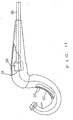
- An exhaust gas purifier shown as Fig. 11 has been disclosed in Japanese Patent Laid-Open No. Hei 3-22913, wherein a punching pipe 02 having a plurality of ventilation holes 03 spaced apart from each other at intervals is disposed along the inner peripheral surface of an expansion chamber 01 connected to an exhaust port of an internal combustion engine.
- a tail pipe 04 directing toward the upstream side is disposed in the expansion chamber 01 at the downstream end thereof in such a manner as to be coaxial therewith.
- An exhaust gas passable catalyst 05 is mounted at the upstream end of the tail pipe 04. Part of an exhaust gas flowing from the exhaust port of the internal combustion engine into the expansion chamber 01 is brought in contact with a catalyst supported on the surface of the punching pipe 03 positioned on the upstream side, to be thus purified; while the exhaust gas in the expansion chamber 01 is brought in contact with the exhaust gas passable catalyst 05 on the downstream side, to be thus purified.
- the purifier shown in Fig. 11 has the following disadvantage.
- a purifier as nearing the inner peripheral surface from the center of the expansion chamber 01, an exhaust gas is significantly reduced in flow rate because of a resistance of the inner peripheral surface of the expansion chamber 01.
- most of the exhaust gas passing through the center of the expansion chamber 01 at a high flow rate tends not to be brought in contact with the catalyst supported on the punching pipe 03 adjacent to the inner peripheral surface of the expansion chamber 01, and to be discharged from the tail pipe 04 to the exterior, thus failing to obtain a sufficient purifying effect by the catalyst supported on the punching pipe 03.
- the exhaust gas passable catalyst 05 is disposed at the center of the downstream side of the expansion chamber 01 in such a manner as to project from the downstream side to the upstream side. Consequently, even if the size and shape of the expansion chamber 01 is set to enhance the scavenging efficiency by the inertia effect of an exhaust gas in a normal operational range of the internal combustion engine as well as the blow-off preventive effect using a reflection wave of the exhaust gas, these effects cannot be achieved by the presence of the above exhaust gas passable catalyst 05, thus failing to enhancing the scavenging efficiency.
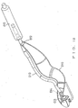
- An exhaust gas purifier shown in Fig. 12 has been disclosed in Japanese Patent Laid-Open No. Hei 3-127017. This is modified from the purifier shown in Fig. 11.
- an upstream end 011 of an expansion pipe 010 formed in a shape similar to that of a prior art expansion chamber is connected to an exhaust port of a two-cycle internal combustion engine mounted on a motor-bicycle (not shown).
- the downstream end 012 (on the right side in the figure) of the expansion pipe 010 is closed.
- An exhaust pipe 013 is branched from the expansion pipe 010 at a position near the upstream end 011, and a thin-wall catalyst element 014 is disposed on the inner peripheral surface of the exhaust pipe 013 at a position near the upstream end.
- catalyst element 014 catalyst is supported on the surface just as in the punching pipe 03 of the purifier shown in Fig. 11.
- the downstream end of the exhaust pipe 013 is connected to a silencer 015.
- JP-A-52110317 discloses an exhaust gas purifier according to the preamble of claim 1.
- an exhaust gas purifier comprising: an expansion pipe having an upstream end for connection to an exhaust gas discharge pipe of an internal combustion engine and a downstream end which is closed, wherein an exhaust gas discharge opening is formed in said expansion pipe adjacent said upstream end thereof, and wherein an exhaust passable thin-walled catalyst element is disposed at the outer periphery of said expansion pipe, characterized in that said exhaust passable thin-walled catalyst element surrounds said expansion pipe upstream end and encloses said exhaust gas discharge opening means; and a sealing sheet enclosedly surrounds said exhaust gas passable thin-walled catalyst element and is operative to exhaust gas pased though said catalyst element and to conduct it therefrom.
- an exhaust gas in the expansion pipe is prevented from increased in temperature due to heat of reaction of catalyst in the expansion pipe, and is kept at a relatively low temperature.
- the expansion pipe can be reduced in size, to reduce the size and weight of the purifier, resulting in the reduced cost.
- the thin-walled catalyst element may comprise a metal sheet having a plurality of holes and a catalyst supported on the surface of the metal sheet.
- the outer periphery of the thin-walled catalyst element facing to the exhaust gas discharging opening may be sealed by a sealing member, and the upstream end of a silencer containing a catalyst extending in the whole cross-section of a flow path may be communicated to a space sealed by the sealing member.
- the expansion pipe is formed in an elongated shape; an elongated silencer containing a catalyst is disposed on the line extending from the downstream end of the expansion pipe; a sealing member for sealing the outer periphery of the thin-walled catalyst element facing to the exhaust gas discharging opening extends from the upstream side to the downstream side of the expansion pipe and reaches the upstream end of the silencer; and a space sealed by the sealing member is communicated to the expansion pipe and the silencer.
- an internal combustion engine including the exhaust gas purifier of the present invention can be mounted on a motor-bicycle with an excellent appearance.
- a secondary air may be supplied to a portion on the downstream side from the exhaust gas discharging opening and on the upstream side from the catalyst in the silencer.
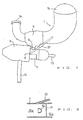
- An opening 1a formed at the upstream end of an expansion pipe 1 is connected to an exhaust port of a two-cycle internal combustion engine mounted on a motor-bicycle (not shown).
- the expansion pipe 1 is formed of a stainless steel (SUS304) sheet which has been subjected to heat-resisting surface treatment.
- the expansion pipe 1 is gradually increased in diameter as nearing the downstream side, and is closed at the downstream end by means of an approximately semi-spherical pipe wall 1b. Namely, the size and shape of the expansion pipe 1 are determined to obtain a high scavenging efficiency by deriving both an inertia effect of an exhaust gas discharged from the two-cycle internal combustion engine (not shown) and a blow-off preventive effect using a reflection wave of the exhaust gas.
- Two exhaust gas discharging opening 2 are formed in a peripheral wall of the expansion pipe 1 near the upstream end so as to be spaced from each other in the longitudinal direction (or in the circumferential direction).
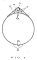
- An exhaust gas passable thin-walled catalyst element 3 is disposed around the outer periphery of the expansion pipe 1 in such a manner as to surround the exhaust gas discharging openings 2. At this time, the catalyst element 3 is separated apart from the openings 2 by a certain gap. Both the sides of the catalyst element 3 are curved toward the expansion pipe 1 and are fixed on the outer peripheral surface of the expansion pipe 1 by welding or the like.
- the catalyst element 3 includes a support formed of a stainless steel (SUS304) sheet having a plurality of small holes 4.
- a water-soluble silica made undercoat layer is formed on the inner and outer surfaces (including surfaces of the small holes 4) of the support.
- a wash coat layer of an active alumina base material mixed with a cerica-based additive and a silica-based binder is formed on the undercoat layer.
- a noble metal catalyst containing platinum (Pt) and rhodium (Rh) at a weight ratio of 20:1 is supported on the wash-coat layer at a ratio of 1-2 g/m 2 .
- the outer periphery of the catalyst element 3 is sealed by a sealing sheet 5.
- An opening 5a is formed in the sealing sheet 5 on the side opposed to the exhaust gas discharging openings 2 of the expansion pipe 1.
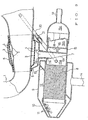
- a communicating pipe 6 is fitted at the upper end thereof in the opening 5a of the sealing sheet 5.
- the communicating pipe 6 passes through an opening 7a of a silencer casing 7 which is disposed in such a manner as to be adjacent to and substantially in parallel to the expansion pipe 1.
- a lower end portion 6a of the communicating pipe 6 is U-shaped in cross-section and is opened to the downstream side (on the left side in fig. 3) of the silencer casing 7.
- a monolithic catalyst 8 having a honey-comb cross-section is charged in the silencer casing 7 on the downstream side.
- An outer casing 9 is disposed in such a manner as to coaxially surround the outer periphery of the monolithic catalyst 8.
- a conical end plate 10 is mounted at the downstream end of the silencer casing 7.
- a plurality of small holes 11 are formed in the end plate 10.
- a silencer chamber 12 formed between the silencer casing 7 and the outer casing 9 is partitioned into two parts by means of a partitioning plate 13. Several pieces of communicating pipes different in length (not shown) pass through the partitioning plate 13, and a tail pipe 14 passes through the outer casing 9. Noise of exhaust gas in the silencer chamber 12 is thus attenuated.
- a space 15 in the silencer casing 7 is partitioned into spaces 15a, 15b by means of a partitioning plate 16 provided upstream of the communicating pipe 6 (on the right side in the figure). Communicating ports 17 are formed in the partitioning plate 17.
- the space 15b is partitioned by means of a check valve (reed valve) 18, to form a space 15c on the right side of the space 15b.
- a secondary air introducing pipe 19 is fitted in the upstream end of the silencer casing 7 (at the right end in the figure) to be communicated to the space 15c.
- the interior of the expansion pipe 1 is communicated to the space 15a of the silencer casing 7 by means of a unburnt oil 1 recovering pipe 20, and a check valve 21 is interposed in the unburnt oil recovering pipe 20.
- an exhaust gas discharged from the two-cycle internal combustion engine flows in the expansion pipe 1, and thereafter it does not reach the semi-spherical pipe wall 1b at the downstream end of the expansion pipe 1 but passes through the exhaust gas discharging openings 2 near the upstream end opening 1a.
- the exhaust gas is then brought in contact with the thin-walled catalyst element 3, flowing in the space 15a in the silencer casing 7 from the space surrounded by the sealing thin plate 5 through the communicating pipe 6, and is brought in contact with the monolithic catalyst 8.
- the exhaust gas flows in the silencer chamber 12 through the small holes 11 to be attenuated in exhaust noise, and thereafter it is discharged from the tail pipe 14 to the atmospheric air.
- the exhaust gas at a high temperature allowed to flow in the expansion pipe 1 is discharged from the exhaust gas discharging openings 2 near the upstream end opening 1a, and the exhaust gas near the semi-spherical pipe wall 1b at the downstream end of the expansion pipe 1 is not heated at a high temperature and thereby it is kept at a low temperature.
- An average temperature of the whole exhaust gas in the expansion pipe 1 is thus lowered, and thereby the propagating speed of the exhaust gas is reduced.
- the expansion pipe 1 can be reduced in size.
- the exhaust gas After passing through the exhaust gas discharging openings 2, the exhaust gas passes through the small holes 4 of the catalyst element 3 in the radial direction in the state that it is not lowered in temperature so much, and is brought in contact with the entire surface of the catalyst element 3. Furthermore, in the space 15a, the exhaust gas is brought in contact with the monolithic catalyst 8 in the state that a necessary secondary air is supplied through the secondary air introducing pipe 19, check valve 18, space 15b and the communicating opening 17, to be thus sufficiently purified. The purifying performance of the exhaust gas can be thus sufficiently enhanced.
- An unburnt oil mixed in the exhaust gas is separated therefrom in the expansion pipe 1, and is fed in the space 15a at a high temperature through the unburnt oil recovering pipe 20, to be thus sufficiently burnt.
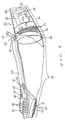
- a casing 30, which is divided into right and left parts, is formed in an elongated shape being substantially similar to that of a common expansion chamber provided on a on-road or off-road motor-bicycle.
- the casing 30 has an exhaust gas suction opening 31 at the upstream end. Ribs 30a projecting outward along the division surfaces are integrated with each other by welding.
- the casing 30 is partitioned, at a position separated apart from the exhaust gas suction opening 31 by about two-third of the whole length, into an expansion chamber 33 and a silencer 34 by means of a partitioning plate 32.
- the exhaust gas suction opening 31 is connected to an exhaust port of a two-cycle internal combustion engine (not shown).
- the expansion chamber 33 has such a size and shape as to achieve a high scavenging efficiency similar to that in the expansion pipe 1 described in the embodiment shown in Figs. 1 to 3.
- a unburnt oil recovering passage 35 is formed in the bottom of the partitioning plate 32 for discharging unburnt oil separated from the exhaust gas in the expansion chamber 33 into the silencer 34.
- two pieces of exhaust gas discharging openings 36 are formed in lower portions relatively near the exhaust gas suction opening 31.
- a thin-walled catalyst element 37 having small holes 38 is wound around the outer periphery of the exhaust gas discharging openings 36.
- a sealing sheet 40 is fixed to the casing 30 in such a manner as to surround the entire periphery of the catalyst element 37, and to seal the exhaust gas discharging openings 36, small holes 38, and a communicating port 39 disposed downstream of the partitioning plate 32 in the state being opened to the silencer 34.
- a secondary air introducing pipe 42 is disposed in a communicating passage 41 sealed by the casing 30 and the sealing sheet 40.
- the rear portion (right side in the figure) of the secondary air introducing pipe 42 extending in the longitudinal direction passes through the sealing sheet 40 and projects to the exterior.
- a reed valve 43 is provided at the front end of the secondary air introducing pipe 42.
- a secondary air is supplied into the secondary air introducing pipe 42 from a secondary air supply apparatus (not shown) connected to the rear end of the secondary air introducing pipe 42, and it flows in the communicating passage 41 through the reed valve 43.
- an exhaust gas flows in the expansion chamber 33 from the internal combustion engine (not shown), passing through the exhaust gas discharging openings 36 and the small holes 38, and flows in the communicating passage 41.
- the exhaust gas is mixed with the above secondary air, before being discharged in the silencer 34.
- a thin-walled catalyst element 44 is provided under the secondary air introducing pipe 42 in such a manner as to extend in the longitudinal direction of the expansion chamber 33.
- the catalyst element 44 has small holes as in the catalyst element 37, and is formed in a hat in cross-section.
- Two pieces of circular thin-walled catalyst elements 45 having small holes, similar to the catalyst element 37, are disposed on the upstream side of the silencer 34.
- the catalyst elements 45 are spaced from each other at a specified interval in the direction perpendicular to the longitudinal direction of the casing 30.
- Two partitioning plates 46a, 46b are provided on the downstream side of the catalyst elements 45.
- An upstream side silencer chamber 47a and a downstream side silencer chamber 47c respectively partitioned by the partitioning plates 46a, 46b are communicated to each other by means of a communicating pipe 48 passing through the partitioning plates 46a, 46b.
- An intermediate silencer chamber 47b is formed between the upstream side silencer chamber 47a and the downstream side silencer chamber 47c.
- the intermediate silencer chamber 47b is communicated to the downstream side silencer chamber 47c by means of a communicating port 49.
- a tail pipe 50 is passes through the downstream end of the casing 30 and the partitioning plate 46b on the downstream side.
- the expansion chamber 33 and the silencer 34 are integrated with each other by means of the common casing 30, and, accordingly, they can be made compact, and also increased in a resistance against vibration and impact because of the forcible integration structure thereof.
- the casing 30 containing the expansion chamber 33 and the silencer 34 has an elongated shape similar to that of the prior art expansion chamber, and, thereby, it can be curved in a desired shape in accordance with the layout of a motor-bicycle (not shown), thus enhancing the appearance of the motor-bicycle.
- the thin-walled catalyst element 37 is provided around the outer periphery of the exhaust gas discharging openings 36 and also the thin-walled catalyst elements 44 are disposed in the elongated communicating passage 41 sealed by the casing 30 and the sealing sheet 40. Accordingly, an exhaust gas discharged from the catalyst element 37 flows in the silencer chamber 47a through the communicating port 39 through the communicating passage 41, and is then brought in contact with the catalyst elements 44. As a result, the purifying efficiency can be further enhanced.
- the silencer 34 is also formed in a relatively elongated shape, and further, three silencer chambers 47a, 47b and 47c are formed by partitioning plates 46a, 46b. This makes it possible to easily obtain desired noise reducing characteristics.
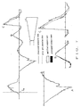
- Fig. 7 is a graph showing pressure waves (shown by the solid line), with respect to the expansion pipe (schematically shown in Fig. 7) in which the exhaust gas discharging openings are formed in the side wall of the expansion pipe on the downstream side, and the prior art expansion pipe. Specifically, this graph shows changes in pressure i . n an exhaust port with an elapse of time since the exhaust port of a two-cycle internal combustion engine is opened (the opened time is shown by the broken line on the left side).
- Fig. 8 is a graph showing changes in pressure in an exhaust port, with respect to an expansion pipe modified from the prior art type in which a thin-walled catalyst element having a plurality of small holes is provided on the inner peripheral surface of an enlarged portion of the expansion pipe, in comparison with the prior art expansion pipe.
- the area of the white portion is narrower than that of the black portion.
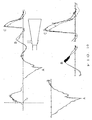
- Fig. 9 is a graph showing changes in pressure in an exhaust port, with respect to expansion pipe shown in Fig. 12 in which the exhaust gas discharging openings are provided on the peripheral surface near the upstream end, in comparison with the prior art expansion pipe.
- the area of the white portion is wider than that of the black portion, thus showing a high scavenging efficiency.
- Fig, 10 is a graph showing changes in pressure in an exhaust port, with respect to the expansion pipe of the present invention in which the thin-walled catalyst element having small holes facing to the exhaust gas discharging openings near the upstream end of the expansion pipe, in comparison with the prior art expansion pipe. It is revealed that a high scavenging efficiency similar to that shown in Fig. 9 can be obtained.
- the scavenging efficiency can be enhanced.
- the exhaust gas purifier of the present invention is applicable to an exhaust system of an internal combustion engine to increase purifying efficiency while keeping the output of the engine at a high level.
Landscapes
- Engineering & Computer Science (AREA)
- Chemical & Material Sciences (AREA)
- Chemical Kinetics & Catalysis (AREA)
- Combustion & Propulsion (AREA)
- Mechanical Engineering (AREA)
- General Engineering & Computer Science (AREA)
- Health & Medical Sciences (AREA)
- Toxicology (AREA)
- Exhaust Gas After Treatment (AREA)
- Exhaust Silencers (AREA)
- Filtering Of Dispersed Particles In Gases (AREA)
- Exhaust Gas Treatment By Means Of Catalyst (AREA)
- Electrical Discharge Machining, Electrochemical Machining, And Combined Machining (AREA)
- Catalysts (AREA)
- Incineration Of Waste (AREA)
- Gas Separation By Absorption (AREA)
- Treating Waste Gases (AREA)
- Separation By Low-Temperature Treatments (AREA)
- Glass Compositions (AREA)
- Separation Of Particles Using Liquids (AREA)
- Vaporization, Distillation, Condensation, Sublimation, And Cold Traps (AREA)
Claims (5)
- Purificateur de gaz d'échappement comportant :dans lequel une ouverture d'évacuation de gaz d'échappement (2 ; 36) est formée dans ledit tuyau d'expansion (1 ; 33) en étant adjacente à ladite extrémité amont (1a) de celui-ci, etun tuyau d'expansion (1 ; 33) ayant une extrémité amont (1a) destinée à être reliée un tuyau d'évacuation de gaz d'échappement d'un moteur à combustion interne et une extrémité aval (1b ; 32) qui est fermée,
dans lequel un élément catalyseur à paroi mince pouvant être franchie par l'échappement (3 ; 37) est disposé à la périphérie extérieure dudit tuyau d'expansion (1 ; 33),
caractérisé en ce que
ledit élément catalyseur à paroi mince pouvant être franchie par l'échappement (3 ; 37) entoure ladite extrémité amont de tuyau d'expansion (1a) et enferme lesdits moyens d'ouverture d'évacuation de gaz d'échappement (2 ; 36), et
une feuille d'étanchéité (5 ; 40) entoure d'une manière enfermant ledit élément catalyseur à paroi mince pouvant être franchie par les gaz d'échappement (3 ; 37) et est active pour évacuer les gaz ayant traversé ledit élément catalyseur (3 ; 37) et les conduire à partir de celui-ci. - Purificateur de gaz d'échappement selon la revendication 1, dans lequel ledit élément catalyseur à paroi mince (3) comprend une feuille de métal ayant une pluralité de trous (4) et un catalyseur supporté sur la surface de ladite feuille de métal.
- Purificateur de gaz d'échappement selon la revendication 1, incluant un silencieux défini par un carter (7),
l'extrémité amont dudit carter de silencieux (7) contenant un catalyseur (8) s'étendant à travers une section transversale complète d'un trajet d'écoulement défini par ledit carter (7), ledit trajet d'écoulement communiquant avec un espace rendu étanche par ledit élément d'étanchéité (5). - Purificateur de gaz d'échappement selon la revendication 1, dans lequel ledit tuyau d'expansion (33) a une forme allongée ;
une plaque de séparation (32) étant disposée dans ledit tuyau d'expansion (33) et définissant un silencieux allongé (34) dans l'extrémité aval dudit tuyau d'expansion (33) ;
un élément catalyseur (45) s'étendant à travers un trajet d'écoulement traversant ledit silencieux (34),
ladite feuille d'étanchéité (40) définissant un espace (41) s'étendant à partir de l'extrémité amont dudit tuyau d'expansion (33) jusqu'à l'extrémité aval de celui-ci ; et
des moyens (39) faisant communiquer ledit espace (41) rendu étanche par ladite feuille d'étanchéité (40) avec ledit trajet d'écoulement à travers ledit silencieux (34) en amont dudit élément catalyseur (45) situé dans celui-ci. - Purificateur de gaz d'échappement selon la revendication 3 ou 4, comportant des moyens (42) pour alimenter de l'air secondaire vers une zone située sur le côté aval à partir de ladite ouverture d'évacuation de gaz d'échappement (36) et sur le côté amont du catalyseur (45) situé dans ledit silencieux (34).
Applications Claiming Priority (4)
| Application Number | Priority Date | Filing Date | Title |
|---|---|---|---|
| JP29602594A JP3369335B2 (ja) | 1994-11-07 | 1994-11-07 | 排気浄化装置 |
| JP296025/94 | 1994-11-07 | ||
| JP29602594 | 1994-11-07 | ||
| PCT/JP1995/002253 WO1996014499A1 (fr) | 1994-11-07 | 1995-11-06 | Epurateur de gaz d'echappement |
Publications (3)
| Publication Number | Publication Date |
|---|---|
| EP0753650A1 EP0753650A1 (fr) | 1997-01-15 |
| EP0753650A4 EP0753650A4 (fr) | 1999-03-03 |
| EP0753650B1 true EP0753650B1 (fr) | 2002-10-23 |
Family
ID=17828146
Family Applications (1)
| Application Number | Title | Priority Date | Filing Date |
|---|---|---|---|
| EP95936096A Expired - Lifetime EP0753650B1 (fr) | 1994-11-07 | 1995-11-06 | Epurateur de gaz d'echappement |
Country Status (12)
| Country | Link |
|---|---|
| US (1) | US5897843A (fr) |
| EP (1) | EP0753650B1 (fr) |
| JP (1) | JP3369335B2 (fr) |
| CN (1) | CN1069734C (fr) |
| AT (1) | ATE226687T1 (fr) |
| CA (1) | CA2180639C (fr) |
| DE (1) | DE69528639T2 (fr) |
| DK (1) | DK0753650T3 (fr) |
| ES (1) | ES2185717T3 (fr) |
| PT (1) | PT753650E (fr) |
| TW (1) | TW302420B (fr) |
| WO (1) | WO1996014499A1 (fr) |
Families Citing this family (7)
| Publication number | Priority date | Publication date | Assignee | Title |
|---|---|---|---|---|
| DE19724244A1 (de) * | 1997-06-09 | 1998-12-10 | Emitec Emissionstechnologie | Katalysator mit Sekundärluft-Zwischeneinleitung für Kleinmotoren |
| ATE513121T1 (de) * | 2004-02-24 | 2011-07-15 | Yamaha Motor Co Ltd | Abgasreinigungsvorrichtung für einen motor |
| US9719388B2 (en) * | 2013-05-16 | 2017-08-01 | Toyota Jidosha Kabushiki Kaisha | Exhaust cooling system for internal combustion engine |
| CN104074590A (zh) * | 2014-06-24 | 2014-10-01 | 梁淑慧 | 一种减少尾气污染的排气管 |
| JP6881334B2 (ja) * | 2018-01-29 | 2021-06-02 | 株式会社豊田自動織機 | 排気ガス浄化装置 |
| JP6797152B2 (ja) * | 2018-05-18 | 2020-12-09 | マレリ株式会社 | 排気浄化装置 |
| JP7567791B2 (ja) | 2019-07-23 | 2024-10-16 | ライオン株式会社 | 口腔用組成物及び歯茎へのマッサージ実感付与剤 |
Family Cites Families (11)
| Publication number | Priority date | Publication date | Assignee | Title |
|---|---|---|---|---|
| US3960509A (en) * | 1974-12-30 | 1976-06-01 | Abriany Raymond R | Catalytic muffler |
| JPS594524B2 (ja) * | 1976-03-12 | 1984-01-30 | ヤマハ発動機株式会社 | 触媒コンバ−タ付排気装置 |
| JPS577767Y2 (fr) * | 1977-02-09 | 1982-02-15 | ||
| FR2460709A1 (fr) * | 1979-07-09 | 1981-01-30 | Renault | Dispositif de protection de reacteurs catalytiques |
| JPS56115810A (en) * | 1980-02-18 | 1981-09-11 | Yamaha Motor Co Ltd | Exhaust device of internal combustion engine using catalyst |
| JPH03127017A (ja) * | 1989-10-13 | 1991-05-30 | Olympus Optical Co Ltd | 内視鏡装置 |
| DE3939921A1 (de) * | 1989-12-02 | 1991-06-06 | Degussa | Anordnung zur katalytischen reinigung der auspuffgase von verbrennungsmotoren, insbesondere nach dem zweitaktprinzip |
| JP2576909B2 (ja) * | 1990-04-03 | 1997-01-29 | 本田技研工業株式会社 | 2サイクルエンジンの排気浄化装置 |
| JP2523395B2 (ja) * | 1990-06-22 | 1996-08-07 | 本田技研工業株式会社 | 2サイクルエンジンの2次空気導入装置 |
| US5139107A (en) * | 1990-12-11 | 1992-08-18 | Kioritz Corporation | Exhaust muffler for internal combustion engines |
| JP2588996Y2 (ja) * | 1993-12-14 | 1999-01-20 | 本田技研工業株式会社 | 排気浄化装置 |
-
1994
- 1994-11-07 JP JP29602594A patent/JP3369335B2/ja not_active Expired - Fee Related
-
1995
- 1995-11-06 CN CN95191493A patent/CN1069734C/zh not_active Expired - Fee Related
- 1995-11-06 DE DE69528639T patent/DE69528639T2/de not_active Expired - Fee Related
- 1995-11-06 CA CA002180639A patent/CA2180639C/fr not_active Expired - Fee Related
- 1995-11-06 AT AT95936096T patent/ATE226687T1/de not_active IP Right Cessation
- 1995-11-06 EP EP95936096A patent/EP0753650B1/fr not_active Expired - Lifetime
- 1995-11-06 PT PT95936096T patent/PT753650E/pt unknown
- 1995-11-06 ES ES95936096T patent/ES2185717T3/es not_active Expired - Lifetime
- 1995-11-06 DK DK95936096T patent/DK0753650T3/da active
- 1995-11-06 US US08/669,309 patent/US5897843A/en not_active Expired - Fee Related
- 1995-11-06 WO PCT/JP1995/002253 patent/WO1996014499A1/fr not_active Ceased
- 1995-11-15 TW TW084112097A patent/TW302420B/zh active
Also Published As
| Publication number | Publication date |
|---|---|
| EP0753650A4 (fr) | 1999-03-03 |
| WO1996014499A1 (fr) | 1996-05-17 |
| US5897843A (en) | 1999-04-27 |
| JP3369335B2 (ja) | 2003-01-20 |
| PT753650E (pt) | 2003-03-31 |
| CA2180639A1 (fr) | 1996-05-17 |
| DE69528639D1 (de) | 2002-11-28 |
| JPH08135436A (ja) | 1996-05-28 |
| CN1069734C (zh) | 2001-08-15 |
| DK0753650T3 (da) | 2003-02-24 |
| EP0753650A1 (fr) | 1997-01-15 |
| DE69528639T2 (de) | 2003-03-13 |
| TW302420B (fr) | 1997-04-11 |
| CA2180639C (fr) | 2004-06-22 |
| ATE226687T1 (de) | 2002-11-15 |
| ES2185717T3 (es) | 2003-05-01 |
| CN1140481A (zh) | 1997-01-15 |
Similar Documents
| Publication | Publication Date | Title |
|---|---|---|
| US7281606B2 (en) | Exhaust sound and emission control systems | |
| JP3314241B2 (ja) | 自動二輪車用エンジンの排気浄化装置 | |
| US5325666A (en) | Exhaust system of an internal-combustion engine | |
| US6935461B2 (en) | Exhaust sound and emission control systems | |
| US5043147A (en) | Combined muffler and catalytic converter exhaust unit | |
| US6892854B2 (en) | Muffler with catalytic converter arrangement; and method | |
| AU676171B2 (en) | Muffler with catalytic converter arrangement | |
| US7296657B2 (en) | Engine exhaust muffler with exhaust emission control function | |
| JP4024127B2 (ja) | 内燃機関の排気装置 | |
| CA2063934C (fr) | Circuit d'echappement pour moteur a combustion interne a cylindres en v, a convertisseur catalytique | |
| EP0753650B1 (fr) | Epurateur de gaz d'echappement | |
| US4506506A (en) | Exhaust emission control device for diesel engine | |
| US6024928A (en) | By-pass flow catalytic converter | |
| US3209532A (en) | Afterburner and muffler device | |
| EP1329599B1 (fr) | Silencieux combiné avec un éclateur à étincelles | |
| JP2000257418A (ja) | 排気消音装置 | |
| US6305493B1 (en) | Exhaust system for internal combustion engines | |
| JP3318696B2 (ja) | 内燃機関の排気浄化装置 | |
| JP3350252B2 (ja) | 排気浄化装置 | |
| JPH0514085B2 (fr) | ||
| JP3350250B2 (ja) | 排気浄化装置 | |
| JP3237333B2 (ja) | 排ガス浄化装置付消音器 | |
| TW368550B (en) | Device for conducting an exhaust gas mass flow and/or for receiving a catalytic converter supporting body | |
| JPH0823287B2 (ja) | 排気消音器 | |
| JPH10205324A (ja) | 触媒付排気装置 |
Legal Events
| Date | Code | Title | Description |
|---|---|---|---|
| PUAI | Public reference made under article 153(3) epc to a published international application that has entered the european phase |
Free format text: ORIGINAL CODE: 0009012 |
|
| 17P | Request for examination filed |
Effective date: 19960709 |
|
| AK | Designated contracting states |
Kind code of ref document: A1 Designated state(s): AT BE CH DE DK ES FR GB GR IE IT LI LU MC NL PT SE |
|
| A4 | Supplementary search report drawn up and despatched | ||
| AK | Designated contracting states |
Kind code of ref document: A4 Designated state(s): AT BE CH DE DK ES FR GB GR IE IT LI LU MC NL PT SE |
|
| 17Q | First examination report despatched |
Effective date: 20011001 |
|
| GRAG | Despatch of communication of intention to grant |
Free format text: ORIGINAL CODE: EPIDOS AGRA |
|
| GRAG | Despatch of communication of intention to grant |
Free format text: ORIGINAL CODE: EPIDOS AGRA |
|
| GRAH | Despatch of communication of intention to grant a patent |
Free format text: ORIGINAL CODE: EPIDOS IGRA |
|
| GRAH | Despatch of communication of intention to grant a patent |
Free format text: ORIGINAL CODE: EPIDOS IGRA |
|
| GRAA | (expected) grant |
Free format text: ORIGINAL CODE: 0009210 |
|
| AK | Designated contracting states |
Kind code of ref document: B1 Designated state(s): AT BE CH DE DK ES FR GB GR IE IT LI LU MC NL PT SE |
|
| REF | Corresponds to: |
Ref document number: 226687 Country of ref document: AT Date of ref document: 20021115 Kind code of ref document: T |
|
| REG | Reference to a national code |
Ref country code: GB Ref legal event code: FG4D |
|
| PGFP | Annual fee paid to national office [announced via postgrant information from national office to epo] |
Ref country code: MC Payment date: 20021031 Year of fee payment: 8 Ref country code: GB Payment date: 20021031 Year of fee payment: 8 Ref country code: DE Payment date: 20021031 Year of fee payment: 8 |
|
| REG | Reference to a national code |
Ref country code: CH Ref legal event code: EP |
|
| PGFP | Annual fee paid to national office [announced via postgrant information from national office to epo] |
Ref country code: SE Payment date: 20021108 Year of fee payment: 8 |
|
| REG | Reference to a national code |
Ref country code: IE Ref legal event code: FG4D |
|
| PGFP | Annual fee paid to national office [announced via postgrant information from national office to epo] |
Ref country code: DK Payment date: 20021114 Year of fee payment: 8 |
|
| PGFP | Annual fee paid to national office [announced via postgrant information from national office to epo] |
Ref country code: ES Payment date: 20021115 Year of fee payment: 8 |
|
| REG | Reference to a national code |
Ref country code: CH Ref legal event code: NV Representative=s name: A. BRAUN, BRAUN, HERITIER, ESCHMANN AG PATENTANWAE |
|
| PGFP | Annual fee paid to national office [announced via postgrant information from national office to epo] |
Ref country code: AT Payment date: 20021119 Year of fee payment: 8 |
|
| PGFP | Annual fee paid to national office [announced via postgrant information from national office to epo] |
Ref country code: CH Payment date: 20021120 Year of fee payment: 8 Ref country code: BE Payment date: 20021120 Year of fee payment: 8 |
|
| PGFP | Annual fee paid to national office [announced via postgrant information from national office to epo] |
Ref country code: LU Payment date: 20021121 Year of fee payment: 8 Ref country code: IE Payment date: 20021121 Year of fee payment: 8 |
|
| PGFP | Annual fee paid to national office [announced via postgrant information from national office to epo] |
Ref country code: FR Payment date: 20021127 Year of fee payment: 8 |
|
| REF | Corresponds to: |
Ref document number: 69528639 Country of ref document: DE Date of ref document: 20021128 |
|
| PGFP | Annual fee paid to national office [announced via postgrant information from national office to epo] |
Ref country code: NL Payment date: 20021130 Year of fee payment: 8 |
|
| PGFP | Annual fee paid to national office [announced via postgrant information from national office to epo] |
Ref country code: GR Payment date: 20021212 Year of fee payment: 8 |
|
| PGFP | Annual fee paid to national office [announced via postgrant information from national office to epo] |
Ref country code: PT Payment date: 20030121 Year of fee payment: 8 |
|
| REG | Reference to a national code |
Ref country code: GR Ref legal event code: EP Ref document number: 20020404260 Country of ref document: GR |
|
| REG | Reference to a national code |
Ref country code: DK Ref legal event code: T3 |
|
| REG | Reference to a national code |
Ref country code: PT Ref legal event code: SC4A Free format text: AVAILABILITY OF NATIONAL TRANSLATION Effective date: 20030121 |
|
| ET | Fr: translation filed | ||
| REG | Reference to a national code |
Ref country code: ES Ref legal event code: FG2A Ref document number: 2185717 Country of ref document: ES Kind code of ref document: T3 |
|
| PLBE | No opposition filed within time limit |
Free format text: ORIGINAL CODE: 0009261 |
|
| STAA | Information on the status of an ep patent application or granted ep patent |
Free format text: STATUS: NO OPPOSITION FILED WITHIN TIME LIMIT |
|
| 26N | No opposition filed |
Effective date: 20030724 |
|
| PG25 | Lapsed in a contracting state [announced via postgrant information from national office to epo] |
Ref country code: LU Free format text: LAPSE BECAUSE OF NON-PAYMENT OF DUE FEES Effective date: 20031106 Ref country code: IE Free format text: LAPSE BECAUSE OF NON-PAYMENT OF DUE FEES Effective date: 20031106 Ref country code: GB Free format text: LAPSE BECAUSE OF NON-PAYMENT OF DUE FEES Effective date: 20031106 Ref country code: AT Free format text: LAPSE BECAUSE OF NON-PAYMENT OF DUE FEES Effective date: 20031106 |
|
| PG25 | Lapsed in a contracting state [announced via postgrant information from national office to epo] |
Ref country code: SE Free format text: LAPSE BECAUSE OF NON-PAYMENT OF DUE FEES Effective date: 20031107 Ref country code: ES Free format text: LAPSE BECAUSE OF NON-PAYMENT OF DUE FEES Effective date: 20031107 |
|
| PG25 | Lapsed in a contracting state [announced via postgrant information from national office to epo] |
Ref country code: MC Free format text: LAPSE BECAUSE OF NON-PAYMENT OF DUE FEES Effective date: 20031130 Ref country code: LI Free format text: LAPSE BECAUSE OF NON-PAYMENT OF DUE FEES Effective date: 20031130 Ref country code: CH Free format text: LAPSE BECAUSE OF NON-PAYMENT OF DUE FEES Effective date: 20031130 Ref country code: BE Free format text: LAPSE BECAUSE OF NON-PAYMENT OF DUE FEES Effective date: 20031130 |
|
| PG25 | Lapsed in a contracting state [announced via postgrant information from national office to epo] |
Ref country code: DK Free format text: LAPSE BECAUSE OF NON-PAYMENT OF DUE FEES Effective date: 20031201 |
|
| BERE | Be: lapsed |
Owner name: *HONDA GIKEN KOGYO K.K. Effective date: 20031130 |
|
| PG25 | Lapsed in a contracting state [announced via postgrant information from national office to epo] |
Ref country code: PT Free format text: LAPSE BECAUSE OF NON-PAYMENT OF DUE FEES Effective date: 20040531 |
|
| PG25 | Lapsed in a contracting state [announced via postgrant information from national office to epo] |
Ref country code: NL Free format text: LAPSE BECAUSE OF NON-PAYMENT OF DUE FEES Effective date: 20040601 |
|
| PG25 | Lapsed in a contracting state [announced via postgrant information from national office to epo] |
Ref country code: DE Free format text: LAPSE BECAUSE OF NON-PAYMENT OF DUE FEES Effective date: 20040602 |
|
| PG25 | Lapsed in a contracting state [announced via postgrant information from national office to epo] |
Ref country code: GR Free format text: LAPSE BECAUSE OF NON-PAYMENT OF DUE FEES Effective date: 20040603 |
|
| GBPC | Gb: european patent ceased through non-payment of renewal fee |
Effective date: 20031106 |
|
| EUG | Se: european patent has lapsed | ||
| REG | Reference to a national code |
Ref country code: DK Ref legal event code: EBP |
|
| REG | Reference to a national code |
Ref country code: CH Ref legal event code: PL |
|
| NLV4 | Nl: lapsed or anulled due to non-payment of the annual fee |
Effective date: 20040601 |
|
| REG | Reference to a national code |
Ref country code: IE Ref legal event code: MM4A |
|
| REG | Reference to a national code |
Ref country code: PT Ref legal event code: MM4A Free format text: LAPSE DUE TO NON-PAYMENT OF FEES Effective date: 20040531 |
|
| PG25 | Lapsed in a contracting state [announced via postgrant information from national office to epo] |
Ref country code: FR Free format text: LAPSE BECAUSE OF NON-PAYMENT OF DUE FEES Effective date: 20041029 |
|
| REG | Reference to a national code |
Ref country code: FR Ref legal event code: ST |
|
| REG | Reference to a national code |
Ref country code: ES Ref legal event code: FD2A Effective date: 20031107 |
|
| PG25 | Lapsed in a contracting state [announced via postgrant information from national office to epo] |
Ref country code: IT Free format text: LAPSE BECAUSE OF NON-PAYMENT OF DUE FEES;WARNING: LAPSES OF ITALIAN PATENTS WITH EFFECTIVE DATE BEFORE 2007 MAY HAVE OCCURRED AT ANY TIME BEFORE 2007. THE CORRECT EFFECTIVE DATE MAY BE DIFFERENT FROM THE ONE RECORDED. Effective date: 20051106 |
|
| PG25 | Lapsed in a contracting state [announced via postgrant information from national office to epo] |
Ref country code: FR Free format text: LAPSE BECAUSE OF NON-PAYMENT OF DUE FEES Effective date: 20031130 |