EP0753692A1 - Système de contrÔle de débit minimum et soupape antiretour - Google Patents
Système de contrÔle de débit minimum et soupape antiretour Download PDFInfo
- Publication number
- EP0753692A1 EP0753692A1 EP96110336A EP96110336A EP0753692A1 EP 0753692 A1 EP0753692 A1 EP 0753692A1 EP 96110336 A EP96110336 A EP 96110336A EP 96110336 A EP96110336 A EP 96110336A EP 0753692 A1 EP0753692 A1 EP 0753692A1
- Authority
- EP
- European Patent Office
- Prior art keywords
- check valve
- valve
- measuring
- control
- housing
- Prior art date
- Legal status (The legal status is an assumption and is not a legal conclusion. Google has not performed a legal analysis and makes no representation as to the accuracy of the status listed.)
- Withdrawn
Links
Images



Classifications
-
- F—MECHANICAL ENGINEERING; LIGHTING; HEATING; WEAPONS; BLASTING
- F04—POSITIVE - DISPLACEMENT MACHINES FOR LIQUIDS; PUMPS FOR LIQUIDS OR ELASTIC FLUIDS
- F04D—NON-POSITIVE-DISPLACEMENT PUMPS
- F04D15/00—Control, e.g. regulation, of pumps, pumping installations or systems
- F04D15/0005—Control, e.g. regulation, of pumps, pumping installations or systems by using valves
- F04D15/0011—Control, e.g. regulation, of pumps, pumping installations or systems by using valves by-pass valves
-
- F—MECHANICAL ENGINEERING; LIGHTING; HEATING; WEAPONS; BLASTING
- F04—POSITIVE - DISPLACEMENT MACHINES FOR LIQUIDS; PUMPS FOR LIQUIDS OR ELASTIC FLUIDS
- F04B—POSITIVE-DISPLACEMENT MACHINES FOR LIQUIDS; PUMPS
- F04B49/00—Control, e.g. of pump delivery, or pump pressure of, or safety measures for, machines, pumps, or pumping installations, not otherwise provided for, or of interest apart from, groups F04B1/00 - F04B47/00
- F04B49/22—Control, e.g. of pump delivery, or pump pressure of, or safety measures for, machines, pumps, or pumping installations, not otherwise provided for, or of interest apart from, groups F04B1/00 - F04B47/00 by means of valves
- F04B49/24—Bypassing
-
- F—MECHANICAL ENGINEERING; LIGHTING; HEATING; WEAPONS; BLASTING
- F16—ENGINEERING ELEMENTS AND UNITS; GENERAL MEASURES FOR PRODUCING AND MAINTAINING EFFECTIVE FUNCTIONING OF MACHINES OR INSTALLATIONS; THERMAL INSULATION IN GENERAL
- F16K—VALVES; TAPS; COCKS; ACTUATING-FLOATS; DEVICES FOR VENTING OR AERATING
- F16K17/00—Safety valves; Equalising valves, e.g. pressure relief valves
- F16K17/02—Safety valves; Equalising valves, e.g. pressure relief valves opening on surplus pressure on one side; closing on insufficient pressure on one side
- F16K17/04—Safety valves; Equalising valves, e.g. pressure relief valves opening on surplus pressure on one side; closing on insufficient pressure on one side spring-loaded
- F16K17/0473—Multiple-way safety valves
-
- F—MECHANICAL ENGINEERING; LIGHTING; HEATING; WEAPONS; BLASTING
- F04—POSITIVE - DISPLACEMENT MACHINES FOR LIQUIDS; PUMPS FOR LIQUIDS OR ELASTIC FLUIDS
- F04B—POSITIVE-DISPLACEMENT MACHINES FOR LIQUIDS; PUMPS
- F04B2205/00—Fluid parameters
- F04B2205/16—Opening or closing of a valve in a circuit
Definitions
- the invention relates to a control system for regulating minimum flow rates, with at least one main passage line, at least one check valve arranged therein, at least one bypass line branching from the main passage line, at least one controllable minimum quantity valve arranged in the bypass line or on the branch of the bypass line and at least one measuring apparatus arranged in and / or on the main passage line for detecting the flow rate.
- the invention includes a check valve, in particular for use in one of the aforementioned minimum flow control systems, with a valve housing with at least one inlet connection and at least one outlet connection and a closing element movably arranged in the valve housing, which in the closed state is caused by a pressure behind the valve and / or is pressed by means of a resetting element against a lower or equal pressure existing in front of the valve against a sealing seat arranged in the valve housing and pointing towards the drain side, and which in the open state is counteracted by a higher pressure existing in front of the valve against a lower pressure existing behind the valve and / or is pushed away from the front sealing seat against a restoring force.
- the control systems mentioned at the outset for controlling minimum flow rates are usually used to protect pumps, for example in feedwater systems in the power plant sector or Like. Used. In such systems, water is pumped from a feed water tank to the boiler via a pump. In order to regulate the amount of water running into the boiler, there is usually a feed water control valve in front of the boiler. On the other hand, since the pump always needs a certain minimum flow rate of medium to avoid thermal overheating, a bypass must be opened according to the regulation of the feed water control valve, through which the excess amount can be returned to the feed water tank. A minimum quantity valve is located in the bypass line to regulate this flow rate through the bypass. This minimum quantity valve is usually controlled depending on the flow rate in the pump.
- Conventional control systems for regulating minimum flow rates are therefore generally constructed in such a way that a measuring orifice, often a Venturi tube, is initially arranged behind the feed water tank to record the flow rate.
- the pump is then located behind this orifice plate, and then a check valve in the main passage line, which acts as a safety valve against backflow in the main passage line, e.g. if the pump fails.
- the feed water control valve is then located behind the check valve.
- a bypass line branches off between the pump and the check valve, which in turn is connected to the feed water tank.
- the minimum flow control valve is located in the bypass line.
- the minimum quantity control valve is motor-driven via the orifice plate and an associated transmitter, eg a Barton cell.
- the bypass line is opened just enough so that the required minimum amount always flows through the pump, regardless of the flow rate into the boiler.
- the flow rate measuring apparatus is integrated in the check valve and has a device for determining the position of a closing element within the check valve, the respective opening cross section of the check valve and thus the flow rate being determinable via the position of the closing element.
- the flow rate measuring apparatus in the check valve can be connected to a display or control device, for example in a control room. In addition, it can be connected to a Control device for any minimum quantity valve can be connected.
- the flow rate measuring apparatus simply has a limit switch which, when the check valve is opened, generates a control and / or control signal beyond a certain opening position.
- This control signal is then preferably forwarded to a simply constructed minimum quantity valve which has an open and a closed position, the minimum quantity valve then being switched into the closed position by the control device only when the check valve is opened beyond a certain opening cross section.
- the flow rate measuring apparatus may generate a continuous control and / or control signal which varies with the respective opening cross section of the check valve.
- the minimum quantity valve is preferably adjustable between the open and closed positions while continuously changing the opening cross section of the valve, the minimum quantity valve being adjusted by the control device in a reciprocal manner depending on the opening cross section of the check valve.
- the display, control and / or control signal can take place in various ways, e.g. electrical, hydraulic, mechanical, by light barrier etc.
- the sub-claims 9 to 31 contain advantageous developments and refinements of the check valve according to the invention.
- the control system for regulating minimum flow rates consists of a main through line (3), a check valve (1) arranged in it, a bypass line (4) deviating from this main through line (3) and a minimum quantity valve (2) arranged in the bypass line (4) ).
- the main passage line (3) leads from a feed water tank (S) via a pump (P) through the check valve (1) and a motor-controlled feed water control valve (9) to a boiler (K).
- the bypass line (4) leads back to the feed water tank (S) via the minimum quantity valve (2) and a back pressure regulator (8).
- the bypass line (4) branches off from the main through line (3) within the check valve (1).
- a flow rate measuring device (5) is integrated in the check valve (1) and has a device (11) for determining the position of a closing element (10) within the check valve (1).
- the position of the closing element (10) enables the respective opening cross section of the check valve (1) and thus the flow rate to be determined.
- the flow rate apparatus (5) is connected to a display or control device (7a) in a control room or the like. Furthermore, the measuring apparatus (5) is connected to a Control device (7b, 7c) for the minimum quantity valve (2) connected.
- the check valve (1) consists of a valve housing (50) with an inlet connection (20) and an outlet connection (30).
- This valve housing (50) has a central wall (52) which runs essentially parallel to a main passage direction (51) running from the inlet connection (20) to the opposite outlet connection (30) and which divides the housing interior into an inlet-side and an outlet-side space.
- a through opening (53) is located in the central wall (52) transversely to the main direction of passage (51). On the outflow side, this through opening (53) is provided with a sealing seat (13). Furthermore, the housing (50) has a mounting wall (60) lying essentially parallel to the central wall (52) on the outlet side in front of the latter.
- a guide bushing (15) is arranged on the mounting wall (60) coaxially to the through opening (53), in which a guide socket (16) of a coaxially arranged valve plate (10) is mounted so that it can move axially in a loose manner. Between the mounting wall (60) and the valve plate (10) there is a spring (14) which presses the valve plate (10) from the mounting wall (60) in the direction of the through opening (53).
- the mounting wall (60) forms part of the housing outer wall (54).
- a measuring rod (17) is arranged on the guide stub (16) in an extension thereof on the mounting wall.
- this measuring rod (17) is guided in a bore (61) through the mounting wall (60) with a sealing ring (62) so that it is sealed against the mounting wall (60) and can be moved outwards.
- the measuring rod (17) projects into a measuring chamber (63) arranged on the mounting wall (60) or formed by the mounting wall (60).
- the sealing ring (62) can be dispensed with. An additional potential leak is thus excluded.
- the measuring device (11) itself can be implemented in various ways. This can be a mechanical, hydraulic, electrical, electronic or optical device, or combinations of the different methods can also be used.
- Fig. 2 and Fig. 4 show a quite simple, inexpensive measuring device according to the invention (11).
- the measuring device (11) consists of a limit switch (12) attached to the mounting wall (60).
- the measuring rod (17), as described above, is guided outwards through the mounting wall (60) and, in a certain open position of the valve plate (10), bumps with its free end against a limit switch (12), which in turn results in a simple and inexpensive minimum quantity -Open / close valve (2) in the bypass line (4) is closed.
- the minimum quantity valve (2) can be a conventional, hydraulically operating open / close valve, which is controlled, for example, by means of a magnetic switch (7c).
- the switching pulse of the limit switch (12) can of course also be passed on to a display device (7a) for control purposes.
- Fig. 3 shows a capacitive measuring recording device (11k) for the continuous determination of the opening position of the check valve (1) or the flow rate.
- a measuring rod (17) made of dielectric material projects into a measuring chamber (63) on the mounting wall (60).
- the measuring chamber (63) there is a type of plate capacitor, the capacitance of which is determined as a function of the dielectric measuring rod (17) introduced into the capacitor.
- an inductive measuring device (11) is also possible.
- the measurement signal is used to control a minimum quantity control valve (2), which is regulated in a continuously operating mode exactly according to the required minimum quantity.
- this signal can also be sent to a control device (7a), e.g. in the control room.
- the position of the check valve plate is continuously via a Ohmic resistance measurement determined.
- an electrical contact is attached to the end of the measuring rod (17) made of conductive material.
- there is a sliding contact pressed against the measuring rod (17) on the mounting wall (60) or in the measuring chamber (63). The resistance between the sliding contact and the contact at the end of the measuring rod (17), which changes with the position of the measuring rod (17), is then determined.
- the measuring rod (17) is preferably guided outwards through the mounting wall (60).
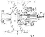
- Fig. 5 and Fig. 6 show two other simple ways to make the position of the measuring rod (17) visible on the outside of the housing. 6 there is a sight glass (64) in the measuring chamber (63) in order to check the position of the measuring rod (17). There are preferably markings or a scale on the measuring rod (17) or in the measuring chamber (63). If, in this exemplary embodiment, a signal is to be used to control a minimum quantity valve (2) or to be passed on to a display device (7a) in a control room, an optical evaluation of the position of the measuring rod (17), e.g. via a video camera with connected image recognition system. Furthermore, e.g. it is also possible to use a light barrier or a reflection light barrier to switch a minimum quantity on / off valve. A light barrier array or the like along the sight glass (64) can be used to control a continuously operating minimum quantity valve (2).
- the measuring rod (17) has a magnetic section (65) and protrudes into a sleeve-like measuring chamber (63) which is attached to the outside in the mounting wall (60), is closed to the outside and is open to the inside.
- the inside diameter of the measuring chamber (63) is so large that the measuring rod (17) fits loosely in the measuring chamber (63) to be led.
- the outside diameter is only slightly larger than the inside diameter.
- This magnetic ring (65) is pulled along by the magnet section (18) of the measuring rod (17) when the measuring rod (17) is displaced and indicates the position of the magnet section (18) or the measuring rod (17) on the outside.
- switching signals or a continuous signal for controlling a minimum quantity valve (2) and for forwarding to a control device (7a) can be generated by means of optical evaluations.
- the measuring rod (17) used in the exemplary embodiments shown can also be dispensed with and the position of the connecting piece (16) or even the position of the valve disk (10) can be determined directly.
- a bypass socket (40) arranged coaxially to the through opening (53) opposite the mounting wall (60) for connecting the bypass line (4).
- the check valve plate (10) actuates a minimum quantity valve (70) which is coaxial with it, so that it is fully open when the check valve plate (10) is closed and releases a passage from the inflow side to the bypass connection piece (40) and when fully open Check valve plate (10) closes the passage from the inflow side of the valve (1) and to the bypass nozzle (40).
- the minimum quantity valve (70) is a three-stage valve suitable for high pressure with a control spindle (80) arranged on the check valve plate (10) with valve cones (81A, 81B) one behind the other coaxially to the check valve plate (10) and a valve plate (82).
- the control spindle (80) is guided axially displaceably in a control bushing (71).
- the front-most valve cone (81A) on the mounting plate presses with its correspondingly shaped outermost rear edge (86) against a sealing seat (83) arranged in the direction of the bypass socket (40) in the control bushing (71) ).
- the valve cones (81A, 81B) and the valve disc (82) located at the rear lie with their cylindrical sliding surfaces (87) on cylindrical wall areas (73) of the control bushing (71).
- the sliding surfaces (87) on the valve cones (81A, 81B) or the valve plate (82) move along the cylindrical wall areas (83) of the control bushing in the direction of the bypass connection piece (40) until the valve cones (81A, 81B) reach extensions (74) of the control bushing (71) so that the liquid medium can flow out on the bypass side.
- the control spindle (80) is then only guided via the valve plate (82) to webs (75) located in the inner wall of the control bushing (71) in the rear area of the bypass fitting.
- the wall areas between the webs (75) are flared to the rear in order to ensure a continuous change in the flow opening when the control spindle (80) is adjusted.
- the control spindle (80) is positively and non-positively connected to the check valve plate (10).
- the Check valve disc with its guide socket (16) is drilled centrally lengthways.
- the part of the control spindle (80) on the mounting wall is pushed into this bore from the bypass socket side and strikes the valve disc (10) with a reinforcing ring (88) of the control spindle (80) which engages in the check valve disc (10).
- this reinforcing ring (80) is surrounded by a seal (89).
- the control spindle (80) is clamped to the check valve plate (10) by means of a spring ring (90) which grips around the end of the control spindle (80) on the mounting wall and presses against the guide socket (16) of the check valve plate (10).
- the check valve plate (10) is guided with its guide socket (16) in the same way in the bushing (15) of the mounting wall (60) as in the previous exemplary embodiments.
- a pressure relief bore (91) is provided, which extends axially from the valve plate (82) on the bypass side through the control spindle (80) to the area of the interior (19) of the guide socket (16).
- a seal (93) is provided between the bushing (15) and the guide socket (16) for sealing.
- the base area of the bypass valve plate (82) and the base area of the guide socket (16) with the control spindle (80) to the interior (19) should preferably be the same size in order to neutralize the usually unknown pressure in the bypass line (4).
- a thread (92) for receiving a threaded rod for easier removal of the control spindle (80) is screwed into the pressure relief bore (91) in the control spindle (80) at the end of the assembly wall on dismantling.
- the three-stage design of the minimum quantity valve (70) allows for higher pressure ratios, especially when the minimum quantity valve (70) is open.
- the minimum quantity valve (70) can also be designed in one, two or, of course, more than three stages if the pressure level is correspondingly lower or greater.
- the mounting wall (60) for removing the valve parts (10, 14, 15, 16, 17, 80, 71) and / or parts of the measuring device (11) is attached to the housing (50) so that it can be removed from the outside. This enables faster maintenance work without having to dismantle the pipes connected to the valve (1) beforehand.
- the entire disassembly of the measuring device and the valve parts is carried out as follows in the embodiment shown in FIG. 6: First, the mounting wall (60) is detached from the housing (50) and carefully to the rear via the measuring rod (17) together with the guide bush (15) deducted from the guide socket (16). The spring (14) is then removed. The locking ring (90) is then removed from the control spindle (80). The valve plate (10) is then removed from the control spindle (50). The control bushing (71) together with the control spindle (80) is then screwed out of the bypass connection piece (40) with the aid of a commercially available hollow socket wrench and removed through the housing opening (55). The control spindle (80) can then be pulled out of the control bushing (71) to the rear.
- control spindle (80) with the control bushing (71) and Pulling out the control spindle (80) from the control bushing (71) can be assisted by a threaded rod or the like, which can be screwed into the mounting plate-side end of the control spindle (80).
- the simple embodiment with a sight glass (64) according to FIG. 6 is particularly suitable, since in principle there is no need to forward the position information to a control system, and only the function of the valve (1) should be visually controllable by the operating personnel on site.
- the valve (1) according to the invention can in principle be used with all liquid media.
- the valve housing (50) is preferably designed as a cast housing. This reduces the manufacturing price, reduces the use of materials and is therefore more resource-efficient.
- the housing (50) can also be made of solid material, e.g. special VA materials, copper or other.
- the structure within a rotated housing and a cast housing (50) is essentially the same except for a few manufacturing changes.
- bypass connection (40) is either screwed into a cross connection of the valve housing (50) and provided with a sealing weld seam, or is butted against the cross connection and welded to it.
- the entire bypass connection piece (40) is screwed to the valve housing (50) via a flange, similarly to the mounting wall (60), in a sealing manner to the housing (50).
Landscapes
- Engineering & Computer Science (AREA)
- General Engineering & Computer Science (AREA)
- Mechanical Engineering (AREA)
- Indication Of The Valve Opening Or Closing Status (AREA)
Applications Claiming Priority (2)
| Application Number | Priority Date | Filing Date | Title |
|---|---|---|---|
| DE1995125061 DE19525061A1 (de) | 1995-07-10 | 1995-07-10 | Regelsystem zur Regelung von Durchflußmindestmengen und Rückschlagventil |
| DE19525061 | 1995-07-10 |
Publications (1)
| Publication Number | Publication Date |
|---|---|
| EP0753692A1 true EP0753692A1 (fr) | 1997-01-15 |
Family
ID=7766435
Family Applications (1)
| Application Number | Title | Priority Date | Filing Date |
|---|---|---|---|
| EP96110336A Withdrawn EP0753692A1 (fr) | 1995-07-10 | 1996-06-27 | Système de contrÔle de débit minimum et soupape antiretour |
Country Status (2)
| Country | Link |
|---|---|
| EP (1) | EP0753692A1 (fr) |
| DE (1) | DE19525061A1 (fr) |
Cited By (3)
| Publication number | Priority date | Publication date | Assignee | Title |
|---|---|---|---|---|
| CN103615384A (zh) * | 2013-12-17 | 2014-03-05 | 青岛禹人水设备新技术有限公司 | 一种耐泥沙式多功能水泵控制阀 |
| CN106369583A (zh) * | 2016-10-18 | 2017-02-01 | 天津市华诺盛源科技有限公司 | 一种锅炉保护装置 |
| EP4506569A1 (fr) * | 2023-08-07 | 2025-02-12 | Wilo Se | Procédé de libération d'un blocage d'une pompe centrifuge et pompe centrifuge |
Families Citing this family (4)
| Publication number | Priority date | Publication date | Assignee | Title |
|---|---|---|---|---|
| DE19710983C2 (de) * | 1997-03-17 | 2002-07-18 | Holter Gmbh & Co | Rückschlagventil |
| DE20213608U1 (de) | 2002-01-29 | 2003-01-09 | WA Holding AG, Grüt | Ventil mit einem Ventileinsatz zur Regelung der Durchflußmenge mit einem zugeordneten Adapter |
| DE202011002712U1 (de) | 2011-02-14 | 2011-05-05 | Tecmara Gmbh | Schutzvorrichtung zum Schutz einer Pumpe, insbesondere zum Schutz der in einem Strömungskreislauf, insbesondere innerhalb einer Anlage vorgesehenen Pumpe vor einer Überhitzung und/oder vor einem Leerlaufen bzw. zum Schutz der in der Anlage vorgesehenen verfahrenstechnischen Prozesseinrichtungen |
| DE102011011202B4 (de) | 2011-02-14 | 2013-03-14 | Tecmara Gmbh | Schutzvorrichtung zum Schutz einer Pumpe, insbesondere zum Schutz der in einem Strömungskreislauf, insbesondere innerhalb einer Anlage vorgesehenen Pumpe vor einer Überhitzung und/oder vor einem Leerlaufen bzw. zum Schutz der in der Anlage vorgesehenen verfahrenstechnischen Prozesseinrichtungen |
Citations (4)
| Publication number | Priority date | Publication date | Assignee | Title |
|---|---|---|---|---|
| US3667495A (en) * | 1970-02-16 | 1972-06-06 | Dopslaff Julius Kg | Proportioning device, especially for water treatment systems |
| WO1985000868A1 (fr) * | 1983-08-15 | 1985-02-28 | Rosaen Nils O | Dispositif de manipulation de fluides |
| DE3344196A1 (de) * | 1983-12-07 | 1985-06-20 | Blum, Albert, 5204 Lohmar | Rueckschlagklappe |
| DE4230697A1 (de) * | 1992-09-14 | 1994-03-31 | Holter Gmbh & Co | Mindestmengenventil |
Family Cites Families (7)
| Publication number | Priority date | Publication date | Assignee | Title |
|---|---|---|---|---|
| DE2605642A1 (de) * | 1976-02-12 | 1977-08-25 | Siebert & Kuehn Dr | Vorrichtung zum ueberwachen der stroemungsmenge von fluessigen oder gasfoermigen medien in leitungen |
| DE3140775C1 (de) * | 1981-10-14 | 1983-05-05 | Zahnradfabrik Friedrichshafen Ag, 7990 Friedrichshafen | Durchflussanzeiger fuer Hydraulikanlagen |
| DE3438405A1 (de) * | 1984-10-19 | 1986-04-24 | Lang Apparatebau GmbH, 8227 Siegsdorf | Dosierkontrolleinrichtung |
| FR2608798B1 (fr) * | 1986-12-19 | 1989-02-24 | Air Liquide | Procede pour controler le debit d'un gaz dans une vanne et generateur de debit mettant en oeuvre ce procede |
| EP0309643B1 (fr) * | 1987-09-28 | 1992-11-25 | Landis & Gyr Business Support AG | Organe pour influencer le débit d'un milieu gazeux ou liquide |
| DE8714982U1 (de) * | 1987-11-11 | 1989-03-09 | Robert Bosch Gmbh, 7000 Stuttgart | Elektrohydraulische Vorrichtung zur lastunabhängigen Regelung eines Volumenstromes proportional zu einem Eingangssignal |
| DE4422749C2 (de) * | 1994-06-29 | 1996-08-29 | Holter Gmbh & Co | Pumpenschutzventil |
-
1995
- 1995-07-10 DE DE1995125061 patent/DE19525061A1/de not_active Withdrawn
-
1996
- 1996-06-27 EP EP96110336A patent/EP0753692A1/fr not_active Withdrawn
Patent Citations (4)
| Publication number | Priority date | Publication date | Assignee | Title |
|---|---|---|---|---|
| US3667495A (en) * | 1970-02-16 | 1972-06-06 | Dopslaff Julius Kg | Proportioning device, especially for water treatment systems |
| WO1985000868A1 (fr) * | 1983-08-15 | 1985-02-28 | Rosaen Nils O | Dispositif de manipulation de fluides |
| DE3344196A1 (de) * | 1983-12-07 | 1985-06-20 | Blum, Albert, 5204 Lohmar | Rueckschlagklappe |
| DE4230697A1 (de) * | 1992-09-14 | 1994-03-31 | Holter Gmbh & Co | Mindestmengenventil |
Cited By (6)
| Publication number | Priority date | Publication date | Assignee | Title |
|---|---|---|---|---|
| CN103615384A (zh) * | 2013-12-17 | 2014-03-05 | 青岛禹人水设备新技术有限公司 | 一种耐泥沙式多功能水泵控制阀 |
| CN103615384B (zh) * | 2013-12-17 | 2016-01-27 | 青岛禹人水设备新技术有限公司 | 一种耐泥沙式多功能水泵控制阀 |
| CN106369583A (zh) * | 2016-10-18 | 2017-02-01 | 天津市华诺盛源科技有限公司 | 一种锅炉保护装置 |
| CN106369583B (zh) * | 2016-10-18 | 2019-04-12 | 天津市华诺盛源科技有限公司 | 一种锅炉保护装置 |
| EP4506569A1 (fr) * | 2023-08-07 | 2025-02-12 | Wilo Se | Procédé de libération d'un blocage d'une pompe centrifuge et pompe centrifuge |
| BE1031871B1 (de) * | 2023-08-07 | 2025-03-10 | Wilo Se | Verfahren zum Lösen einer Verstopfung einer Kreiselpumpe und Kreiselpumpe |
Also Published As
| Publication number | Publication date |
|---|---|
| DE19525061A1 (de) | 1997-01-16 |
Similar Documents
| Publication | Publication Date | Title |
|---|---|---|
| DE3001458C2 (fr) | ||
| EP2306160A1 (fr) | Organe de mesure et compteur de débit | |
| EP1759176B1 (fr) | Capteur de debit | |
| DE102018201515A1 (de) | Autonomes Chemikalieneinspritzsystem für Öl- und Gasbohrlöcher | |
| EP3688459B1 (fr) | Dispositif de détection de la qualité d'un liquide dans un tube d'alimentation | |
| DE102008062521A1 (de) | Strömungssensor für fluide Medien | |
| EP0413198B1 (fr) | Arrangement pour la mesure de la température d'un liquide passant à travers une conduite | |
| EP2898246B1 (fr) | Vanne de commande de écoulement tridimensionnel optimisée avec des caracteristiques de commande linéaire | |
| EP0753692A1 (fr) | Système de contrÔle de débit minimum et soupape antiretour | |
| DE102006062858B4 (de) | Baueinheit bestehend aus einem Anschlußstück und einem mechanischen Strömungssensor | |
| DE102019104413A1 (de) | Druckmindereranordnung | |
| DE102004028759B4 (de) | Strömungssensor | |
| DE102010005459A1 (de) | Absperrarmatur | |
| DE1212042B (de) | Differenzdruck-Anzeigevorrichtung | |
| EP0853754B1 (fr) | Procede et dispositif de mesure de la pression hydrostatique, en particulier de celle des eaux souterraines | |
| DE102005052385B4 (de) | Druckminderer | |
| EP0388736A1 (fr) | Compteur à turbine | |
| EP0301258B1 (fr) | Procédé pour mesurer le débit des fluides | |
| DE202016103116U1 (de) | Filteranordnung | |
| DE3036020C2 (de) | Vorrichtung zur Übertragung der Änderung von Betriebszuständen von einem in Rohren oder Behältern angeordneten Meßelement auf eine außerhalb angebrachte Anzeige- und/oder Schalteinrichtung | |
| DE2049172C3 (de) | Einrichtung für die Anzeige der Verstopfung eines Druckflüssigkeitsfilters | |
| DE4403178C1 (de) | Volumendurchflußmesser | |
| CH628430A5 (en) | Flow meter for liquid and gaseous media | |
| EP4008844A1 (fr) | Système de protection contre les fuites | |
| DE102005006478B4 (de) | Verteilerventil |
Legal Events
| Date | Code | Title | Description |
|---|---|---|---|
| PUAI | Public reference made under article 153(3) epc to a published international application that has entered the european phase |
Free format text: ORIGINAL CODE: 0009012 |
|
| AK | Designated contracting states |
Kind code of ref document: A1 Designated state(s): AT BE DE DK ES FI FR GB IT NL SE |
|
| STAA | Information on the status of an ep patent application or granted ep patent |
Free format text: STATUS: THE APPLICATION IS DEEMED TO BE WITHDRAWN |
|
| 18D | Application deemed to be withdrawn |
Effective date: 19970716 |