EP0753773A1 - Dispositif connecteur opto-électrique - Google Patents
Dispositif connecteur opto-électrique Download PDFInfo
- Publication number
- EP0753773A1 EP0753773A1 EP96110286A EP96110286A EP0753773A1 EP 0753773 A1 EP0753773 A1 EP 0753773A1 EP 96110286 A EP96110286 A EP 96110286A EP 96110286 A EP96110286 A EP 96110286A EP 0753773 A1 EP0753773 A1 EP 0753773A1
- Authority
- EP
- European Patent Office
- Prior art keywords
- plug
- line
- light
- electrical plug
- electrical
- Prior art date
- Legal status (The legal status is an assumption and is not a legal conclusion. Google has not performed a legal analysis and makes no representation as to the accuracy of the status listed.)
- Withdrawn
Links
- 230000003287 optical effect Effects 0.000 claims abstract description 61
- 230000008878 coupling Effects 0.000 claims description 28
- 238000010168 coupling process Methods 0.000 claims description 28
- 238000005859 coupling reaction Methods 0.000 claims description 28
- 239000000463 material Substances 0.000 claims description 6
- 239000011810 insulating material Substances 0.000 claims description 5
- 230000000149 penetrating effect Effects 0.000 claims 1
- 239000004020 conductor Substances 0.000 abstract description 15
- 238000003780 insertion Methods 0.000 abstract description 9
- 230000037431 insertion Effects 0.000 abstract description 9
- 230000001681 protective effect Effects 0.000 description 14
- 230000005540 biological transmission Effects 0.000 description 12
- 239000013307 optical fiber Substances 0.000 description 7
- 238000013461 design Methods 0.000 description 5
- 230000008054 signal transmission Effects 0.000 description 5
- 230000008901 benefit Effects 0.000 description 3
- 239000002184 metal Substances 0.000 description 3
- 238000002788 crimping Methods 0.000 description 2
- 238000006073 displacement reaction Methods 0.000 description 2
- 238000005516 engineering process Methods 0.000 description 2
- 239000000835 fiber Substances 0.000 description 2
- 230000010354 integration Effects 0.000 description 2
- 238000000034 method Methods 0.000 description 2
- 238000003825 pressing Methods 0.000 description 2
- 230000008569 process Effects 0.000 description 2
- 238000005507 spraying Methods 0.000 description 2
- 238000005406 washing Methods 0.000 description 2
- 230000002457 bidirectional effect Effects 0.000 description 1
- 238000004140 cleaning Methods 0.000 description 1
- 238000011109 contamination Methods 0.000 description 1
- 230000000694 effects Effects 0.000 description 1
- 229920006332 epoxy adhesive Polymers 0.000 description 1
- 239000003365 glass fiber Substances 0.000 description 1
- 230000036039 immunity Effects 0.000 description 1
- 238000002347 injection Methods 0.000 description 1
- 239000007924 injection Substances 0.000 description 1
- 238000009434 installation Methods 0.000 description 1
- 238000004519 manufacturing process Methods 0.000 description 1
- 238000012544 monitoring process Methods 0.000 description 1
- 230000035515 penetration Effects 0.000 description 1
- 238000012545 processing Methods 0.000 description 1
- 230000008439 repair process Effects 0.000 description 1
- 238000003892 spreading Methods 0.000 description 1
- 230000007480 spreading Effects 0.000 description 1
- 238000012549 training Methods 0.000 description 1
Images


Classifications
-
- G—PHYSICS
- G02—OPTICS
- G02B—OPTICAL ELEMENTS, SYSTEMS OR APPARATUS
- G02B6/00—Light guides; Structural details of arrangements comprising light guides and other optical elements, e.g. couplings
- G02B6/24—Coupling light guides
- G02B6/36—Mechanical coupling means
- G02B6/38—Mechanical coupling means having fibre to fibre mating means
- G02B6/3807—Dismountable connectors, i.e. comprising plugs
- G02B6/381—Dismountable connectors, i.e. comprising plugs of the ferrule type, e.g. fibre ends embedded in ferrules, connecting a pair of fibres
- G02B6/3817—Dismountable connectors, i.e. comprising plugs of the ferrule type, e.g. fibre ends embedded in ferrules, connecting a pair of fibres containing optical and electrical conductors
Definitions
- the invention relates to a connectable to a connecting line, electrical plug device such as a plug or coupling socket, which has a base body receiving the electrical contacts, and the connecting wires are each connected to the connecting heads of the connecting contacts and in addition to the electrical line wires, at least one optical line wire in the line is embedded and inserted into the connector.
- Such a plug-in device is intended to serve the purpose of connecting an external device, for example a washing machine, to the mains (house network) and at the same time to an electrical control bus, the signal transmission from the socket to the external device being optically avoided to prevent interference from the mains voltage he follows.
- optical signals are not influenced by currents or voltages.
- DE 32 26 265 A1 describes a flexible electrical line which, in addition to the electrical conductors for connecting a device to the mains, also contains a light guide via which optical signals can be transmitted.
- DE 32 27 770 C2 describes an electrical plug-in device with a plug and a coupling socket which enables the connection of a flexible mains cable and also optically connects an optical fiber installed on the building side to an optical fiber of the flexible cable to be connected.
- at least one contact part of the electrical plug-in device is also designed as an optical fiber plug-in device.
- the plug-in device connects the electrical and the optical part of a line to the building's electrical supply lines and the optical data lines.
- bus systems For remote switching, remote control, regulation and monitoring of devices, electrical bus systems are used which have bus couplers at the ends of the bus lines, to which the control inputs or outputs of the devices can be connected, if necessary via interfaces.
- the bus coupling units can contain complex electronic circuit arrangements with a microprocessor and are able to generate and send data telegrams as well as to receive and evaluate them, as well as to process incoming control commands.
- Such a bus system for building system technology is described in EP 0344609 B1.
- the object of the invention is to provide an electrical plug-in device such as a plug or coupling socket for the simultaneous connection of an electrical device to the mains and to a bus line system, with which the transmission of light signals is made possible.
- the optical arrangement should be independent of the electrical arrangement.
- the plug device according to the invention is generally designed on the basis of conventional plug devices for the mains supply.
- connection of a device should remain as unproblematic as before, whereby the temporary or permanent removal of the device, e.g. B. for cleaning purposes, from the bus system by the user himself by pulling the power plug.
- connection of an external one far away from the corresponding wall socket Device can be done via a separate extension line, which has a plug on the one hand and a coupling socket on the other.
- supply lines and control lines advantageously run together in one line from the socket to the external device. Accordingly, it is mentioned in the preamble of claims 1 and 9 that the optical line wires are embedded in the line. It follows that no ordinary electrical line can be used, but one with at least one embedded optical conductor, the jacket of the line then having a prepared bed into which the optical conductor can be clipped or pressed, for example. However, the invention is also intended to apply in the event that the optical conductor is not embedded in the line, but is guided in parallel and separately to the electrical connecting line, for example connected to the outside of the electrical line with clips or cable ties and together with the electrical line into the grommet of the plug or the coupling socket is inserted.
- the advantage is that a common electrical line and everyone suitable optical conductor can be used.
- control lines are designed as light guides and the light exchange takes place through the electrical plug device.
- the advantage of the training according to the invention is that the integration of external devices, such as household appliances in a bus system, for example in a bus system according to the "European Installation Bus Association” (EIBA), can be user-friendly and user-friendly, the connection and disconnection from Bus by the user of the device itself by plugging or pulling the power plug, so that the device receives voltage or is de-energized at the same time. Because the two systems are integrated independently of one another in the plug device, the usual electrical contacts, such as pins and plug contacts, can be used without changes, thereby making the plug device economical to produce.
- EIBA European Installation Bus Association
- the plug device according to the invention can thus be produced in a simple manner despite the increased technical and multifunctional use.
- Essential for the function of the optical signal transmission is the exact adherence to the configuration of the light entry or exit to the electrical contacts, here to the plug pins or the protective contact or the plug contacts of the coupling.
- the two variants according to claims 1 and 9 are different designs of the plug devices, the variant on which the patent claim 1 is based based on a so-called “flexed plug device", while the variant on which the patent claim 9 is based, a reconnectable plug device represents.
- flexed connector offers the possibility of producing the connecting line, base body together with electrical and optical equipment as a pre-assembled unit and then encasing it with the insulating jacket.
- the electrical contact connections are made in a manner known per se by the electrical wires L, N and possibly the protective conductor being connected to the connection heads of the plug-in contacts and the protective conductor by crimping or crimping connections.
- the light guides of the connecting line are attached to the base body with receptacles which are adapted to the cross section of the light guides and strain relief elements with which the position of the light guides is fixed.
- the ends of the light guides are inserted into the receptacles until the position of their optically effective end faces enables the light to enter or exit in the area of the light windows.
- the optically effective cross-sectional end face of the light guide can be flush with the edge of the receptacle in the area of the light window.
- a sleeve-like receptacle for the light guide can be preferred up to the light window of the insulating jacket.
- the end face of the receptacle and the end face of the light guide lie in the plane of the light window; the end face of the light guide is then at the same time light window of the insulating jacket.
- This embodiment is advantageous if no lens coupling is provided or if special translucent front bodies, such as light expansion optics or light concentrators, are dispensed with in the light window.
- Conical bodies can be used as light expansion optics or light concentrators. It may also be sufficient to use an essentially flat disk which serves as a diffusing screen.
- the light body can be attached to the end of the light guide.
- the clamping elements serve to fix the position of the light guide, for example to prevent unintentional displacements such as can occur during transport of the preassembled unit for further processing, but also to secure the position of the light guide in the case of a finished plug-in device if the connecting cable is subject to strong mechanical tensile stress is subjected.
- the clamping means can be designed as extensions of the side of a sleeve-like receptacle opposite the light window, which clamp the inserted light guide by deformation.
- a resilient design means that there is no need for subsequent deformation for the purpose of clamping the light guide.
- the clamping can be barbed. The coaxial alignment of the clamps to the receptacles prevents the light guide from kinking.
- releasable terminals are also provided for the connection ends of the optical line wires, which are designed so that they do not damage the wire jacket or do not significantly deform the cross section of the light guide.
- a large-area contact surface is advantageously provided, the contact pressure of a clamping screw being transmitted to the jacket of the optical wire via a profiled pressure piece.
- a spring can also be used to generate the clamping force.
- the optical wires should be guided with a relatively large bend so that kinking is prevented.
- the design of the plug device according to the invention enables simplex operation for message transmission, half-duplex operation and full-duplex operation.
- a bidirectional bus one fiber or two fibers can be used.
- only one light guide is advantageously used, the light windows being arranged centrally, for example in the middle between the plug pins or plug-in contacts. With this arrangement, half-duplex operation is appropriate, which meets the requirements for building system technology.
- the plug-in device permits two insertion positions offset by 180 ° and the central arrangement of the light window is dispensed with for design reasons, two diametrically opposed light windows are provided, for example via one Y splitter are coupled to the light guide. If this configuration is available for both the plug and the coupling socket, each pair of light windows is always optically coupled to one another in the assembled plug device (plug and coupling socket). Transmission losses are largely prevented. If only the plug or the coupling socket has this double configuration, the optical coupling takes place in each insertion position via a light window.
- each light guide is coupled to a light window.
- the position of the light windows in a plug-in device with distinctive features can be freely selected within certain limits, for example, the Light windows can be arranged on an axis between the electrical contacts or in parallel. In the case of a plug-in device with two plug-in positions offset by 180 °, the information given above applies analogously to the plug-in device with only one light guide.
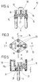
- the connector 1 according to FIGS. 1 and 2 is a connector which is permanently connected to the connecting line 2.
- Such a plug in connection with the connecting line is mainly used for connecting external devices to the power grid.
- a signal connection is established from a bus line via the plug to the external device, so that this device can be controlled remotely.
- the plug 1 is a so-called “flexed” or “molded” plug, because the insulating jacket of the plug 1 is molded onto the end of the connecting line 2 in the injection mold by spraying.
- the insulating jacket is advantageously made of rubber or PVC.
- the insulating jacket is formed from the plug body 3, which forms the contour for the receptacle in a corresponding socket, a handle part 4 and a grommet 5 in the area of the cable entry.
- the connector 1 is an angled connector with a connecting line 2 inserted into the connector 1 transversely to the connector pins 6.
- the plug 1 is designed as a protective contact plug with two different protective contact systems, a first with two opposite edge contacts 7 on the long sides of the plug body 3 and a second with an insertion socket 8 on the end face 9 of the plug body 3.
- the plug 1 fits a Belgian-style socket Standard and together with a socket according to German standards.
- a base body 10 made of hard-elastic insulating material is embedded in the plug body 3.
- the plug pins 6 and a U-shaped spring clip 11 are attached to this “hard core”, the free legs of which form the edge contacts 7 and the plug-in socket 8 is integrally formed on the middle leg of the latter.
- the insert body 10 consists of a base plate 12 with a substantially diamond-like plan with a longitudinal axis 13 and a transverse axis 14. In the diametrically opposite corners of the transverse axis 14, the base plate 12 has cylindrical receptacles 15 for the plug pins 6, which with their rear ends over the Level of Base plate 12 protrude and are designed as connection heads 16.
- connection heads 16 form crimp sleeves into which the ends of the line wires L and N are inserted and are inseparably fastened to the plug pins 6 by pressing the crimp sleeves together (FIG. 6).
- the base plate 12 On the diametrically opposite corner sides of the longitudinal axis 13 are perpendicular to the base plate 12 retaining webs 17, 17a formed on the base plate, on which the spring clip 11 is clipped. As can best be seen from FIGS. 5 and 6, the retaining webs 17, 17a protrude by an amount "x" on the plane of the base plate 12 adjacent to the plug pins 6.
- the holding web 17a is expanded to a chamber 18 which serves to receive the plug-in contact 8. If the plug 1 is plugged into a corresponding socket, this chamber 18 also serves to receive the plug pin inserted into the plug contact 8.
- the chamber 18 is protected against the penetration of insulating jacket material by walls, which are not described in any more detail.
- the spring clip 11 has a crank 19 on its central leg corresponding to the size of the amount "x". This part of the spring clip 11 is completely encased on the finished plug according to FIG. 2 by the material of the insulating jacket.
- the spring clip 11 has a crimp contact 20 to which the protective conductor of the connecting line 2 is connected.
- the crimp contact 20 passes through the base plate 12 at an opening, not specified.
- cylindrical receptacles 21 are provided for the ends of the light guides 22, 23. These receptacles 21 are designed as bores in the base plate 12 and continue as sleeves on the plane adjacent to the plug pins 6.
- the sleeves are pulled up to the front side 9 of the plug 1 and are surrounded by the material of the insulating jacket according to FIG. 2.
- the light guides 22, 23 inserted into the receptacles 21 are flush with the end face 9 of the plug and form light windows 24, 25. Light signals enter the plug through one of the light windows, and light signals emerge from the plug 1 through the other light window.
- the configuration of the light windows 24, 25 to the connector pins 6 or the protective contact is determined.
- the configuration of the light windows 24, 25 is determined in such a way that a light window 24 is located at the intersection of the connecting line 27 of the two connector pins with the perpendicular 26 and the light window 25 is arranged at a distance therefrom on the vertical 26.
- the distance between the light windows 24, 25 should be so large that mutual interference by stray light is avoided; u. U. elastic separating lips can be provided between the light windows 24, 25, for example molded onto the insulating jacket.
- the light windows 24 a, 25 a are located on a line 28 parallel and at a distance from the line 27.
- the arrangement of the light windows 24a, 25a to the perpendicular 26 is preferably mirror-symmetrical.
- the configurations of the light windows described above enable light to be transmitted between plug 1 and the associated socket in a specific plug-in position of the plug.
- plug-in devices in accordance with DIN 49 440 can also be fulfilled for signal transmission in that the plug has light windows assigned in pairs, ie for each light guide 22, 23 two light windows, which are then coupled to the light guide via Y-splitters.
- a corresponding configuration according to FIG. 1a of light windows could be provided for a plug according to FIG. 1 in such a way that further light windows 24b, 25b and the diametrically opposite windows 24a, 24b and 25a, 25b are to be coupled via Y splitter 32 to a light guide 22, 23.
- the light losses that occur from a Y-splitter can be coped with.
- Clamping means 29 arranged coaxially with the receptacles 21 are provided for strain relief of the light guides 22, 23.
- FIGS. 1 and 2a shows a modified arrangement of the optical transmission device according to FIGS. 1 and 2. While in the optical transmission device according to FIGS. 1 and 2 the optically effective cross-sectional end face is flush with the end face 9 of the plug and forms the light window 24, 25 2a, a body 51 acting as a light expansion optics or light concentrator is arranged in front of the optically effective cross-sectional end face of the line core 22. In the simplest case, this body 51 can be designed as a diffuser.
- this body 51 has an unspecified bore and is plugged onto the end of the optical line core 22.
- the body 51 has a lens effect and focuses incident light from the end face 9 onto the optically effective cross-sectional end face the optical line core 22.
- the body 51 is intended to expand the light coming via the line core 22 on the end face 9 and to emit it in a parallel light beam with a substantially larger diameter.
- the end face of the body 51 is spherical. In the case of a flat design, the body 51 acts as a diffusing screen and distributes the light coming through the optical line wire 22 over the entire end face. Spreading losses are then to be taken into account.
- the length of the sleeve-like receptacles 21 is shortened.
- the end of the wire 22 is surrounded by a sleeve 54 made of metal, which is glued to the jacket of the wire 22.
- the optically effective cross-sectional end face of the cable core is polished.
- a glass fiber line bundled from many individual optical fibers is used as the optical line core 22.
- the clamping means 29 serve as locking elements into which the metal sleeve is snapped in with an edge (not shown). This arrangement can be used in place of the arrangement shown in FIG. 2. It offers the advantage that partial soiling of the light window 24 does not lead to an interruption in the signal transmission.
- FIGS. 1, 2 and 2a is designed for a two-channel optical fiber transmission with the optical fibers 22, 23, so that half-duplex and full-duplex operation is optionally possible.
- Half-duplex operation is economically possible with one channel, that is to say with only one light guide 22.
- a correspondingly designed plug then advantageously has only one, arranged in the middle between the pins 6 on the axis 27 (FIG. 1), Light window 24, the optical transmission device as shown in Fig. 2a and described above, can be formed. It should be noted that the optical transmission devices shown in FIGS. 1, 2 and 2a can of course also be used for a coupling socket.
- the receptacle 21 is designed as a sleeve attached to the base body. It is supported on the one hand with a stop on the base body or the crossbar of the spring clip 11, and on the other hand it is fastened on the base body with locking elements, which are also not described in more detail.
- the sleeve-like receptacle 21 is inserted and locked in the base body 10 and is then part of the base body.
- the receptacle 21 is made of a translucent material and at the same time is designed as a light window 24. A smooth bottom molded onto the sleeve is used as the light window 24. The bottom can also be lenticular.
- the shaft of the sleeve opposite the light window 24, which is compressed by hot deformation and clamps the inserted line wire, serves as the clamping means.
- slotted expansion sleeves 30 are used as the clamping means 29, which are integrally formed in the edge area around the receptacle 21 on the rear side of the base plate 12 opposite the plug pins 6.
- the ends of the light guides are in the expansion sleeves 30 plugged in. Insertion funnels (unspecified) facilitate insertion. With the resilient slotted parts of the expansion sleeves 30, the light guide ends 22, 23 are clamped and secured against inadvertent displacement.
- the clamping means 29 are designed as crimp sleeves 31, which are formed on the middle leg of the spring clip 11 via tabs 33 and are bent into a position aligned coaxially with the receptacles 21.
- the inserted light guide 22, 23 is clamped by compressing the crimp sleeve 31.
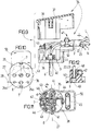
- FIGS. 9 to 12 show a plug 34 for the detachable connection of line 2.
- the plug 34 consists of a base body 36 which carries the electrical contacts, such as plug pins 6 and a protective contact clip 35, made of insulating material and a cover 37 also made of insulating material.
- connection of the two parts 36, 37 takes place with a central, unspecified screw, for which a screw receptacle 38 is provided in the base body 36 and a threaded guide 39 is provided in the hood 37.
- connector 34 has two protective contact systems.
- the protective contact bracket 35 has two opposite edge contacts 7, which extend on the long sides of the plug body 36.
- the protective contact clip 35 also has a plug-in contact 8 on the end face 9 of the base body 36.
- the base body 36 has receptacles 40 for the connection heads 41 of the plug pins 6 on its inside 44 opposite the plug pins 6.
- connection heads 41 are designed as screw terminals for connecting the line wires L, N.
- connection heads 41 are designed as screw terminals for connecting the line wires L, N.
- a screw terminal 42 arranged on the protective contact clip 35 is provided.
- Turrets 43 are provided which are arranged in relation to the connecting line 27 of the connection heads 41 on the inside 44 of the base body 36 facing away from the strain relief device 45.
- These turrets 43 are integrally formed on the base body 36. They have a receptacle 46 designed as a longitudinal bore for the optical lines 22, 23, which emerge on the end face 9 of the base body 36 and form a coaxial arrangement with the light windows 24a, 25a there.
- two light windows 24a, 25a are arranged on connector 34 (FIG. 10) on a parallel 28 running at a distance from connection line 27 of connector pins 6.
- One light window is intended for the light entry and the other for the light exit, the arrangement being provided to the left and right of the central perpendicular 26 and the distances from the axis 26 being the same.
- the arrangement of the light windows 24a, 25a can optionally be provided to the left or right of the connecting line 27.
- single-channel transmission with only one light guide 22 or 23 can also be provided in this embodiment.
- the light window 24a or 25a is arranged centrally in the middle between the pins 6 on the axis 27 (FIG. 11).
- the hood attachment 38, 39 placed at this point in FIG. 11 is then to be provided at another location.
- the optical line conductors 22, 23 are such light guides or optical waveguides, the core of which is surrounded by a jacket. For the connection, the ends of the optical line wires 22, 23 are inserted into the receptacles 46 until their possibly polished end faces are flush with the end face 9 of the plug body 6 to lock. The light windows 24a, 25a are thus formed.
- the position of the optical line wires 22, 23 is fixed with the clamping means 47, which are integrated in the turret 43. These are screw terminals, which act on the jacket of the optical conductor 22, 23 via a pressure piece 48.
- the pressure pieces 48 can have profiles, not specified, which are adapted to the cross-section of the line wires 22, 23.
- FIG. 12 shows an embodiment with lens coupling of the optical line wires 22, 23.
- lenses 49 are inserted into the light windows 24a, 25a, and the ends of the optical line wires 22, 23 are inserted up to the surface of the lenses 49.
- the usual strain relief device 45 for the connecting line 2 is designed like a clamp and is arranged on an arm 50 which projects transversely to the plug body 36 and is covered by the hood 37.
- Figures 13 and 14 show a movable socket, a so-called coupling socket. It is a flexed coupling corresponding to that described at the beginning flexed connector , i.e. a non-reconnectable socket outlet.
- FIGS. 13 to 16 those reference numerals from the remaining FIGS. 1 to 8 have been adopted which designate the same parts.
- Line 2 of the coupling socket is inserted centrally.
- the base body 10, according to FIG. 13, is designed to receive the plug-in contacts 52.
- the plug-in contacts 52 are designed as resilient plug-in terminals for the plug pins 6 of the plug.
- the receptacles for the plug-in contacts 52 are chambers which are separated from one another by a recess, which is not designated in any more detail and which receives the crosspiece 55 of the spring clip 11.
- Crimp sleeves 56 protrude from the chambers from the plug-in contacts 52.
- a crimp sleeve 56 protrudes from the crosspiece 55 from the recess.
- the ends of the electrical line wires L, N and protective contact are connected to the crimp sleeves 56.
- socket pot 53 has a cup-shaped receptacle for the plug, called socket pot 53.
- This socket pot 53 is made of the same material as the base body 10 and is integrally formed with the base body 10 or is part of the base body 10 ( Fig. 13).
- the insulating jacket 3, 4, 5 is thus formed at this point by the end face 9 of the base body. Accordingly, the insulating body contains a light window 24 and a receptacle 21 for the light guide 22.
- the light window 24 is arranged centrally, ie in the middle between the plug contacts 52, on the axis 26.
- the end of the optical line wire 22 of the line 2 is inserted into the receptacle 21 of the base body 10 and fixed with a clamping means 29.
- the clamping means 29 is a resilient clamping sleeve, which is formed by angled parts of the transverse web 55 of the spring clip 11.
- 15 shows a detailed receptacle 21 for coupling the light guide 22 to the light window 24.
- 15 is formed in three stages and is used to couple the optically effective cross-sectional end face of the light guide 22 to the light window 22.
- the coupling takes place here via a conical light concentrator 51, which has an unspecified neck or extension, which is approximately the same Diameter of the optically effective cross-sectional end face of the light guide 22 corresponds.
- the end of the light guide 22 is inserted into the upper part of the receptacle 21 and the light concentrator with its neck in the middle part of the receptacle 21 and with its conical part in the lower part of the receptacle 21 and additionally glued with an epoxy adhesive.
- the light concentrator 51 can also be integrated in the two-component process when the base body 10 is sprayed into the base body.
- FIG. 16 shows an arrangement which is similar to the arrangement in FIG. 2a.
- the metal sleeve 54 is additionally supported by the crossbar 55.
- the base body 10 is like the base body 10 according to FIGS. 4 to 8 with the parts 2, 11, 52 formed as a pre-assembled unit and is then encased with the insulating jacket 3, 4, 5 by spraying or pressing.
Landscapes
- Physics & Mathematics (AREA)
- General Physics & Mathematics (AREA)
- Optics & Photonics (AREA)
- Connector Housings Or Holding Contact Members (AREA)
Applications Claiming Priority (4)
| Application Number | Priority Date | Filing Date | Title |
|---|---|---|---|
| DE19523824 | 1995-06-30 | ||
| DE19523824 | 1995-06-30 | ||
| DE19526267A DE19526267A1 (de) | 1995-06-30 | 1995-07-19 | Elektrischer Stecker mit Lichtleiter |
| DE19526267 | 1995-07-19 |
Publications (1)
| Publication Number | Publication Date |
|---|---|
| EP0753773A1 true EP0753773A1 (fr) | 1997-01-15 |
Family
ID=26016416
Family Applications (1)
| Application Number | Title | Priority Date | Filing Date |
|---|---|---|---|
| EP96110286A Withdrawn EP0753773A1 (fr) | 1995-06-30 | 1996-06-26 | Dispositif connecteur opto-électrique |
Country Status (1)
| Country | Link |
|---|---|
| EP (1) | EP0753773A1 (fr) |
Cited By (5)
| Publication number | Priority date | Publication date | Assignee | Title |
|---|---|---|---|---|
| WO2006032345A1 (fr) * | 2004-09-21 | 2006-03-30 | Fraunhofer-Gesellschaft zur Förderung der angewandten Forschung e.V. | Prise femelle multifonction et fiche male multifonction pour montage d'une fibre flexible |
| CN102623823A (zh) * | 2011-01-31 | 2012-08-01 | 安华高科技光纤Ip(新加坡)私人有限公司 | 具有光电性能及易清洁光学表面的插头的薄型连接器组件 |
| WO2013139649A1 (fr) * | 2012-03-21 | 2013-09-26 | Huber+Suhner Ag | Ensembles raccordement de câbles isolés du milieu environnant |
| US9057862B2 (en) | 2010-09-21 | 2015-06-16 | Huber+Suhner Ag | Environmentally sealed cable breakout assemblies |
| US20170146746A1 (en) * | 2014-06-05 | 2017-05-25 | Innovience International Bv | Solution for Installing an In-House or In-Building Optical Data Network |
Citations (5)
| Publication number | Priority date | Publication date | Assignee | Title |
|---|---|---|---|---|
| DE3227770A1 (de) * | 1982-07-24 | 1984-01-26 | Gebrüder Merten GmbH & Co KG, 5270 Gummersbach | Mehrpolige elektrische steckvorrichtung |
| JPS60188912A (ja) * | 1984-03-07 | 1985-09-26 | Nec Corp | 電気・光複合コネクタ |
| EP0166860A2 (fr) * | 1984-06-01 | 1986-01-08 | Messerschmitt-Bölkow-Blohm Gesellschaft mit beschränkter Haftung | Couplage de conducteurs de lumière pour un appareil médical à laser |
| EP0256892A2 (fr) * | 1986-08-20 | 1988-02-24 | Plessey Overseas Limited | Connecteur hybride |
| US4814118A (en) * | 1984-07-02 | 1989-03-21 | Polaroid Corporation | Method of molding a connector for optical fibers |
-
1996
- 1996-06-26 EP EP96110286A patent/EP0753773A1/fr not_active Withdrawn
Patent Citations (5)
| Publication number | Priority date | Publication date | Assignee | Title |
|---|---|---|---|---|
| DE3227770A1 (de) * | 1982-07-24 | 1984-01-26 | Gebrüder Merten GmbH & Co KG, 5270 Gummersbach | Mehrpolige elektrische steckvorrichtung |
| JPS60188912A (ja) * | 1984-03-07 | 1985-09-26 | Nec Corp | 電気・光複合コネクタ |
| EP0166860A2 (fr) * | 1984-06-01 | 1986-01-08 | Messerschmitt-Bölkow-Blohm Gesellschaft mit beschränkter Haftung | Couplage de conducteurs de lumière pour un appareil médical à laser |
| US4814118A (en) * | 1984-07-02 | 1989-03-21 | Polaroid Corporation | Method of molding a connector for optical fibers |
| EP0256892A2 (fr) * | 1986-08-20 | 1988-02-24 | Plessey Overseas Limited | Connecteur hybride |
Non-Patent Citations (2)
| Title |
|---|
| L.C.SOLLMAN: "OPTICAL INSTRUMENTATION BUS", NAVY TECHNICAL DISCLOSURE BULLETIN, vol. 10, no. 2, December 1984 (1984-12-01), ARLINGTON US, pages 59 - 62, XP002016598 * |
| PATENT ABSTRACTS OF JAPAN vol. 10, no. 41 (P - 429)<2098> 18 February 1986 (1986-02-18) * |
Cited By (12)
| Publication number | Priority date | Publication date | Assignee | Title |
|---|---|---|---|---|
| WO2006032345A1 (fr) * | 2004-09-21 | 2006-03-30 | Fraunhofer-Gesellschaft zur Förderung der angewandten Forschung e.V. | Prise femelle multifonction et fiche male multifonction pour montage d'une fibre flexible |
| US9057862B2 (en) | 2010-09-21 | 2015-06-16 | Huber+Suhner Ag | Environmentally sealed cable breakout assemblies |
| US9182564B2 (en) | 2010-09-21 | 2015-11-10 | Huber + Suhner Ag | Environmentally sealed cable breakout assemblies |
| US9548601B2 (en) | 2010-09-21 | 2017-01-17 | Huber + Suhner Ag | Environmentally sealed cable breakout assemblies |
| CN102623823A (zh) * | 2011-01-31 | 2012-08-01 | 安华高科技光纤Ip(新加坡)私人有限公司 | 具有光电性能及易清洁光学表面的插头的薄型连接器组件 |
| US8672559B2 (en) * | 2011-01-31 | 2014-03-18 | Avago Technologies General IP Singapore Pte. Ltd. | Thin connector assembly that has optical and electrical capabilities and that includes a plug having an optical surface that can be easily wiped clean |
| WO2013139649A1 (fr) * | 2012-03-21 | 2013-09-26 | Huber+Suhner Ag | Ensembles raccordement de câbles isolés du milieu environnant |
| CN104321677A (zh) * | 2012-03-21 | 2015-01-28 | 胡贝尔舒纳公司 | 环境密封的线缆分支组件 |
| AU2013234534B2 (en) * | 2012-03-21 | 2016-07-28 | Huber+Suhner Ag | Environmentally sealed cable breakout assemblies |
| US9548603B2 (en) | 2012-03-21 | 2017-01-17 | Huber+Suhner Ag | Environmentally sealed cable breakout assemblies |
| US20170146746A1 (en) * | 2014-06-05 | 2017-05-25 | Innovience International Bv | Solution for Installing an In-House or In-Building Optical Data Network |
| US10466424B2 (en) * | 2014-06-05 | 2019-11-05 | Innovience International Bv | Solution for installing an in-house or in-building optical data network |
Similar Documents
| Publication | Publication Date | Title |
|---|---|---|
| DE19504013C1 (de) | Anschlußvorrichtung zur wahlfreien Herstellung eines wiederverwendbaren elektrischen Anschlusses bzw. Abgriffs an mehradrigen elektrischen Leitungen | |
| DE60100091T2 (de) | Optischer und elektrischer Steckverbinder | |
| DE10015259C2 (de) | Steckerbuchse, Verfahren zu deren Herstellung, sowie ein die Steckerbuchse aufweisender Steckverbinder | |
| DE10015950C2 (de) | Steckerbuchse, Herstellungsverfahren derselben und einen die Steckerbuchse aufnehmenden optischer Steckverbinder | |
| DE3227770C2 (de) | Mehrpolige elektrische Steckvorrichtung | |
| DE3517388A1 (de) | Anschlussteil fuer ein faser-optisches kabel | |
| DE19507669C2 (de) | Optischer Mehrfach-Steckverbinder, insbesondere für Rund- oder Zip-cord-Kabel | |
| DE19525214A1 (de) | Elektrische Steckvorrichtung | |
| EP0753773A1 (fr) | Dispositif connecteur opto-électrique | |
| DE19831851C1 (de) | Einrichtung zum Anschluß von Lichtwellenleiterkabeln | |
| EP1128198A1 (fr) | Connecteur hybrid optique et électrique | |
| DE4009273A1 (de) | Verbindungsstueck fuer eine elektrisch leitende steckverbindung | |
| CH674281A5 (fr) | ||
| DE3932709A1 (de) | Elektrischer steckverbinder | |
| DE20202835U1 (de) | Optische Verbindungseinrichtung | |
| DE19526267A1 (de) | Elektrischer Stecker mit Lichtleiter | |
| EP0512234A2 (fr) | Balai en charbon | |
| EP1792218B1 (fr) | Prise femelle multifonction pour montage d'une fibre flexible | |
| DE19531633A1 (de) | Optisches Datenkommunikationssystem | |
| DE19851867C2 (de) | Vorrichtung zur lösbaren Verbindung von Lichtwellenleitern miteinander oder mit elektrooptischen Sende- und/oder Empfangseinrichtungen | |
| EP0771049A2 (fr) | Dispositif de raccordement électrique pour le réseau domestique | |
| EP0442046B1 (fr) | Module de connexion pour réseau local | |
| EP0746061A2 (fr) | Dispositif de couplage électrique | |
| DE60116245T2 (de) | Klammer für elektrische Kabel | |
| EP0753774A2 (fr) | Dispositif de connexion électrique |
Legal Events
| Date | Code | Title | Description |
|---|---|---|---|
| PUAI | Public reference made under article 153(3) epc to a published international application that has entered the european phase |
Free format text: ORIGINAL CODE: 0009012 |
|
| AK | Designated contracting states |
Kind code of ref document: A1 Designated state(s): AT BE CH DE ES FI FR GB GR IT LI NL PT SE |
|
| 17P | Request for examination filed |
Effective date: 19970304 |
|
| STAA | Information on the status of an ep patent application or granted ep patent |
Free format text: STATUS: THE APPLICATION IS DEEMED TO BE WITHDRAWN |
|
| 18D | Application deemed to be withdrawn |
Effective date: 20020103 |