EP0746061A2 - Dispositif de couplage électrique - Google Patents
Dispositif de couplage électrique Download PDFInfo
- Publication number
- EP0746061A2 EP0746061A2 EP96108380A EP96108380A EP0746061A2 EP 0746061 A2 EP0746061 A2 EP 0746061A2 EP 96108380 A EP96108380 A EP 96108380A EP 96108380 A EP96108380 A EP 96108380A EP 0746061 A2 EP0746061 A2 EP 0746061A2
- Authority
- EP
- European Patent Office
- Prior art keywords
- plug
- socket
- splitter
- light
- windows
- Prior art date
- Legal status (The legal status is an assumption and is not a legal conclusion. Google has not performed a legal analysis and makes no representation as to the accuracy of the status listed.)
- Withdrawn
Links
Images





Classifications
-
- G—PHYSICS
- G02—OPTICS
- G02B—OPTICAL ELEMENTS, SYSTEMS OR APPARATUS
- G02B6/00—Light guides; Structural details of arrangements comprising light guides and other optical elements, e.g. couplings
- G02B6/24—Coupling light guides
- G02B6/36—Mechanical coupling means
- G02B6/38—Mechanical coupling means having fibre to fibre mating means
- G02B6/3807—Dismountable connectors, i.e. comprising plugs
- G02B6/381—Dismountable connectors, i.e. comprising plugs of the ferrule type, e.g. fibre ends embedded in ferrules, connecting a pair of fibres
- G02B6/3817—Dismountable connectors, i.e. comprising plugs of the ferrule type, e.g. fibre ends embedded in ferrules, connecting a pair of fibres containing optical and electrical conductors
Definitions
- the invention relates to an electrical plug-in device which consists of a socket and a plug, the plug being insertable into the socket in different orientations of its contact elements and the plug-in device also transmitting signals via optical fibers.
- a flexible electrical cable which, in addition to the electrical supply lines for the network connection of a device, contains a light guide via which signals can be transmitted. While electrical signal lines, which are laid together with supply lines in a common cable, are disturbed by the supply lines (crosstalk), light signals are not influenced by currents or voltages of the supply lines.
- an electrical plug-in device with a socket which enables the connection of a power cable to installed power lines and also optically connects an optical fiber installed on the building side to an optical fiber of the cable to be connected. At least this is a contact part of the electrical plug device of the socket is simultaneously designed as an optical fiber plug device.
- the plug device therefore connects the electrical and the optical part of a cable to the building's electrical supply lines and the optical data lines.
- the plug can be inserted into the socket in different orientations of its contact elements, but it causes considerable constructional and technical difficulties to carry out the light transmission through the electrical contact elements.
- the invention has for its object to provide an electrical connector that enables the transmission of light signals, the light signal transmission is structurally and spatially separated from the electrical contact elements and enables the transmission of light signals in each of the two orientations of the plug with respect to the socket .
- the socket and / or the plug contains at least two windows for the light exchange outside the contact elements. Two of these windows are coupled by a Y-splitter and arranged symmetrically to one another, so that one of them, in every orientation of the plug, coincides with the same window of the other part of the socket and plug. In this way it is achieved that the connector in any orientation the socket can be plugged in, a light transition is guaranteed in every orientation.
- three windows are arranged in a row, the middle window being in the center and therefore being used with every orientation of the plug, while the two outer windows are arranged laterally.
- the two outer windows are connected to each other by the Y-splitter. It is possible to use the two outer windows at the same time, or just one of these two windows.
- the Y splitter is preferably part of a light guide connector which has connection devices for connecting external light guides.
- another Y-splitter or an unbranched light guide can be contained in the light guide connector.
- the light guide connector is used to position the light guide precisely inside the socket or plug in order to be able to connect external light guides.
- the light guide connector preferably contains a shaped body in which the Y-splitter and possibly further light guides are embedded.
- a socket SD is provided, into which a plug ST can be inserted.
- the socket SD is fundamentally designed like a normal standardized socket of the power supply network. It contains a base 10 made of insulating material, on which electrical connection terminals 11 for current conductors and contact terminals 12 are attached.
- a protective conductor bracket 13 is provided, which has a protective conductor connecting terminal 13a and lateral spring arms 13b for engaging the connector ST.
- the base 10 is provided with expanding claws which can be tensioned to engage in a flush-mounted box and hold the socket therein.
- a front frame 14 is fastened to the base 10 and can be placed against the wall when the base 10 is immersed in the wall box.
- a pot-shaped insert 15 is placed, by an aperture frame 16 is surrounded.
- This insert 15 forms the socket for receiving the plug body. It has holes 17 for inserting the contact elements of the plug and slots in its side surface through which the protective conductor spring arms 13b protrude in order to be able to engage the plug body.
- the insert 15 is fastened to the base 10 with a screw 18.
- the three windows of an optical fiber connector 20 are arranged in a row. These windows are labeled 21a, 21b and 22.
- the window 22 is located in the geometric center of the socket. Its center lies where the plane in which the contact elements 12 or the holes 17 lie and the plane in which the spring arms 13b lie intersect.
- the row of windows 21a, 22, 21b runs at right angles to the straight line connecting the centers of the holes 17 and in the plane in which the spring arms 13b lie.
- the windows are arranged in the floor level of the insert 15.
- the light guide connector 20 contains a light guiding Y-splitter 23, one branch 23a leading to the window 21 and the other branch 23b leading to the window 21b. Both branches unite to form a trunk 23c, which protrudes rearward in the base 10.
- a curved light guide 24 also extends in the base 10 from the middle window 22 to the rear. This light guide 24 here consists of a single strand.
- a housing 25 which carries an electronic circuit on a circuit carrier 26 in the form of a circuit board.
- This circuit is, for example, a bus coupler BA for a house control system, the bus cables of which are installed in the building and are connected to the bus coupler.
- the bus coupler BA generates signals for an external electrical device that is connected to the power supply via the SD socket on the one hand, but is also intended to exchange signals with the bus system installed on the building.
- the bus system works electronically, however, the signals are led from the SD sockets as light signals to the external devices.
- the signal traffic from the external device to the bus coupling unit BA also takes place using light signals.
- the bus coupler BA contains a light transmitter S and a light receiver E, which are preferably arranged on the circuit carrier 26. Only the light receiver E is visible in FIG. 3, while the light transmitter S is also visible in FIG. 4.
- the light transmitter is arranged opposite the end of the light guide 24, so that its light signals are coupled into this middle light guide 24, which leads to the window 22.
- the light transmitter is, for example, a light emitting diode.
- the light receiver E is arranged opposite the stem 23c of the Y splitter 23, so that the light signals which reach the Y splitter 23 through the windows 21a and 21b are led to the light receiver E.
- the light receiver is, for example, a phototransistor or a photodiode.
- the BA bus coupling unit transmits light signals via the light transmitter S. to the external electrical device and via the light receiver E, it receives light signals from the external electrical device.
- the connector 20 has a molded body made of plastic, in which the Y-splitter 23 and the light guide 24 are embedded, for example by injection molding.
- the figures 5 and 6 show a variant of the connector 20, wherein the Y-splitter 23 consists of a molded part which surrounds the other light guide 24, such that the windows 21a, 22, 21b are all in a row, the two connections of which are arranged opposite one another Light guides are also in a row.
- the Y-splitter 23 and the light guide 24 are contained in a housing 30 in which the window-side ends of the light guides are fixed with high precision and which is then poured out with a hardening plastic 31.
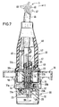
- Fig. 7 shows the electrical connector, wherein the plug ST is inserted into the socket SD.
- the plug ST has three windows 31a, 32, 31b on its end face, which faces the bottom wall of the socket SD, and which correspond to the corresponding windows of the socket.
- the plug ST contains an optical fiber connector 40.
- the optical fiber connector 40 contains a Y-splitter 33 and an unbranched central optical fiber 34.
- the branches 33a, 33b of the Y splitter end in the windows 31a, 31b, while the light guide 34 ends in the middle window 32.
- the light guide connector 40 of the connector ST is inserted into this connector in a defined position and orientation and there e.g. attached by gluing. It contains a connecting device 41 made of a rigid ring 42 in which a deformable sleeve 43 is seated. By tightening a screw 44 which is screwed into the ring 42, the sleeve 43 is deformed and it clamps the light guides, which are inserted into the sleeve from both ends, in a mutual axial alignment.
- Fig. 7 it is shown that the stem 33c of the Y-splitter 33 is inserted into the sleeve 43 from one end and from the other end a light guide 45 of a cable 46 connected to the connector ST.
- Another connecting device 41 is also for the further light guide 47 of the cable is provided, which is optically coupled to the light guide 34 of the light guide connector 40.
- the cable 46 contains the two light guides 45 and 47, which lead to the connected external device and whose light signals are converted there into electrical signals.
- the end of the cable 46 is connected to a strain relief 49, which in turn protrudes from the plug base 50.
- Light signals which are emitted by the external device are transmitted via the light guide 45 to the light guide connector 40 of the plug and are emitted there by the branches 33a, 33b. These signals are received by the branches 23a, 23b of the light guide connector 20 of the socket SD and to the light receiver E directed where they are converted into electrical signals.
- Signals which are emitted by the light transmitter S of the socket SD are transmitted through the central light guide 24 of the socket SD to the central light guide 34 of the plug ST and from there to the light guide 47 which leads to the external device.
- the two-pole plug which has two contact elements in the form of protruding pins, can be inserted into the socket in two different orientations, since the plug device has no unmistakable device. Such an unmistakable device would only permit insertion in a very specific orientation.
- branch 33b aligns with branch 21a and branch 33a aligns with branch 23b.
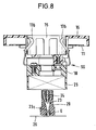
- Fig. 8 shows a socket SD, which is generally designed in the same way as the socket of the first embodiment.
- the circuit carrier 26, ie the circuit board that carries the light transmitter and the light receiver is attached directly to the light guide connector 20 and connected to it.
- the light guide connector contains a cavity in which the light receiver E is arranged and a further cavity in which the light transmitter S is arranged.
- the advantage of this embodiment is that a predetermined fixed coupling of the light receiver and light transmitter to the respective light guide exists that cannot be changed by installation tolerances.
- the light guide connector is also inserted into the base until it stops and glued there.
- the connector ST of the embodiment of FIG. 9 differs from the first embodiment in that there is no Y-splitter in it. Accordingly, the plug also has only two windows 31b, 32.
- the window 32 serves to transmit light signals from the socket to the light guide 47.
- the window 31b serves to transmit light signals from the light guide 45 to the socket via the unbranched light guide 45 contained in the light guide connector 40.
- the window 31b comes to coincide with either the window 21a or the window 21b of the socket.
- the socket If the plug does not contain a Y-splitter, the socket must contain a Y-splitter.
- the socket can be designed without a Y-splitter, but in this case the plug must contain a Y-splitter.
- FIGS. 10 and 12 These options are shown schematically in FIGS. 10 and 12.
- the socket SD on the left and the plug ST on the right are shown here, the socket containing a light transmitter S and a light receiver E.
- the plug ST is connected to a cable which is connected at its other end to a light transmitter S and a light receiver E.
- the socket SD contains a Y-splitter 23, which is connected to the receiver E of the socket is, while the connector ST contains two unbranched light guides 34, 45.
- Fig. 11 the situation is reversed.
- the plug ST contains a Y-splitter 33, which is coupled to the receiver E of the external device, while the socket SD contains two unbranched light guides 24, 45.
- the Y-splitter is switched so that its trunk is always connected to a light receiver E. In this way, halving light losses through beam splitting are avoided.
- FIG. 12 shows a socket SD in front view in a further exemplary embodiment, the distribution of the windows 21a, 21b, 21c, 21d being recognizable.
- the windows are arranged at the corners of an imaginary square, the diagonally opposite windows 21a, 21b being connected by a first Y-splitter 23 'and the other two windows 21c, 21d by a second Y-splitter 23' '.
- the Y-splitters are of course located inside the socket and are only shown schematically in FIG.
- the associated plug has four corresponding windows in the same arrangement as the socket and also two Y-splitters or one Y-splitter and an unbranched light guide.
- the socket SD contains a Y-splitter 23, the trunk of which is optically coupled to an optical transceiver SE and the branches 23a, 23b of which are arranged symmetrically to the central axis of the socket SD. There is no other light guide in the socket.
- the ST connector contains a Y-splitter 33, the two branches 33a, 33b of which are in alignment with the branches 23a, 23b of the socket SD when the plug is inserted. There is no other light guide in the connector.
- the stem 33c of the Y splitter 33 is optically coupled to the end of an optical fiber 45 which extends through the cable 46.
- the embodiment according to FIG. 13 is useful if a central arrangement of the light guides in the plug and socket is not possible. It is useful to fork the Y splitters on both sides because information runs in both directions during bidirectional data transmission. A single-wire coupling of the plug to the Y-splitter of the socket would lead to very high attenuation (loss of light). Such damping is avoided by the Y-splitters 23 and 33 in the socket and plug.
- the windows at which the light passes between the socket and the plug consist of the ends of the respective light guides.
- the connector can also be used to connect an optical fiber system installed on the building to an external device.
- no light transmitter and no light receiver are arranged in the socket, but the socket is connected to the installed light guide system.
- Both the plug and the socket can be used in conjunction with conventional sockets and plugs that do not contain any light guides. Both the socket and the plug are therefore compatible with conventional plugs and sockets if only electrical connections are to be made.
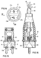
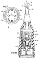
- FIGS. 14 to 16 show the plug of a connecting cable and in FIGS. 17 to 19 the socket provided at the other end of the connecting cable.
- the connecting cable 60 contains, in addition to the electrical lines, the two light guides 45 and 47.
- the plug ST and the coupling or movable socket SD of the connecting cable 60 are to be used in each of the two possible positions without a specific polarity of the electrical contact elements being important.
- the connector ST is provided with four windows 21a, 21b, 21c and 21d arranged at the corners of a square, at each of which a light guide A, B, C or D ends.
- the light guides C and D, whose windows 21c and 21d are also arranged diagonally to one another, are combined in a Y-splitter 23 ′′, the trunk of which is connected to a connecting device 62.
- the light guide 45 is connected to the connection device 61 and the light guide 47 to the connection device 62.
- the two light guides A and B form - in relation to the plug-side end of the connection cable 60 - the transmitting light guide through which light signals from the connection cable are led into a socket.
- the light guides C and D form receiving light guides through which the cable receives light signals from the socket. It can be seen that the plug ST can be inserted into the associated socket in different orientations and that in any case one of the windows 21a, 21b sends light signals into the socket, while one of the windows 21c, 21d receives light signals from the socket.
- the movable socket SD or coupling at the other end of the connecting cable 60 also contains four windows 21a, 21b, 21c and 21d, the diagonally opposite windows 21a and 21b being reception windows and the likewise diagonally opposite windows 21c and 21d being transmission windows.
- the light guides A and B are combined in a Y-splitter, the trunk of which is connected to a connecting device 61 and the light guides C and D are also combined in a Y-splitter, the trunk of which is connected to a connecting device 62.
- a plug can be inserted into the movable socket SD in either of the two possible orientations, whereby a transmission window of the plug always coincides with a reception window of the movable socket SD and a reception window of the plug coincides with a transmission window of the movable socket.
Landscapes
- Physics & Mathematics (AREA)
- General Physics & Mathematics (AREA)
- Optics & Photonics (AREA)
- Connector Housings Or Holding Contact Members (AREA)
- Optical Couplings Of Light Guides (AREA)
Applications Claiming Priority (4)
| Application Number | Priority Date | Filing Date | Title |
|---|---|---|---|
| DE19519896 | 1995-05-31 | ||
| DE19519896 | 1995-05-31 | ||
| DE19528262 | 1995-08-01 | ||
| DE19528262A DE19528262A1 (de) | 1995-05-31 | 1995-08-01 | Elektrische Steckvorrichtung |
Publications (2)
| Publication Number | Publication Date |
|---|---|
| EP0746061A2 true EP0746061A2 (fr) | 1996-12-04 |
| EP0746061A3 EP0746061A3 (fr) | 1997-06-11 |
Family
ID=26015624
Family Applications (1)
| Application Number | Title | Priority Date | Filing Date |
|---|---|---|---|
| EP96108380A Withdrawn EP0746061A3 (fr) | 1995-05-31 | 1996-05-25 | Dispositif de couplage électrique |
Country Status (1)
| Country | Link |
|---|---|
| EP (1) | EP0746061A3 (fr) |
Family Cites Families (2)
| Publication number | Priority date | Publication date | Assignee | Title |
|---|---|---|---|---|
| US4915466A (en) * | 1988-09-15 | 1990-04-10 | Spacelabs, Inc. | Reversible optical or electro-optical connector |
| GB9027748D0 (en) * | 1990-12-20 | 1991-02-13 | Baroid Technology Inc | Two-way fibre optic communication system |
-
1996
- 1996-05-25 EP EP96108380A patent/EP0746061A3/fr not_active Withdrawn
Also Published As
| Publication number | Publication date |
|---|---|
| EP0746061A3 (fr) | 1997-06-11 |
Similar Documents
| Publication | Publication Date | Title |
|---|---|---|
| DE60100091T2 (de) | Optischer und elektrischer Steckverbinder | |
| EP1783521B1 (fr) | Connecteur et systeme de connexion RJ-45 | |
| EP0824714B1 (fr) | Systeme de prises electriques | |
| EP1390790B1 (fr) | Dispositif de repartition optique et cable de connexion de guides d'ondes optiques | |
| DE102006000702B4 (de) | Anschlussvorrichtung | |
| DE69736583T2 (de) | Faseroptisches Steckersystem | |
| WO2003093888A1 (fr) | Connecteur enfichable hybride | |
| EP0516930B1 (fr) | Dispositif pour connecter des conduites | |
| EP0061772A1 (fr) | Module prise électro-optique | |
| EP0395708B1 (fr) | Connecteur | |
| DE3227770A1 (de) | Mehrpolige elektrische steckvorrichtung | |
| DE19525214A1 (de) | Elektrische Steckvorrichtung | |
| DE102007062658A1 (de) | Hybrid-Steckverbindung | |
| EP0822622A2 (fr) | Prise électrique avec sécurité pour les enfants | |
| EP0746061A2 (fr) | Dispositif de couplage électrique | |
| EP0304639A2 (fr) | Dispositif à prise pour la transmission de l'énergie électrique et de signaux optiques | |
| EP1792218B1 (fr) | Prise femelle multifonction pour montage d'une fibre flexible | |
| DE19528262A1 (de) | Elektrische Steckvorrichtung | |
| DE2715846B2 (de) | Lichtkoppelndes Bauelement für gedruckte Schaltungen | |
| DE19531633A1 (de) | Optisches Datenkommunikationssystem | |
| EP0753773A1 (fr) | Dispositif connecteur opto-électrique | |
| EP0771049B1 (fr) | Dispositif de raccordement électrique pour le réseau domestique | |
| DE4101962A1 (de) | Anordnung zur uebertragung von daten mit mindestens einem lichtwellenleiter | |
| DE3048512A1 (de) | "verbindungsleitung zur uebertragung von signalen" | |
| DE19542167A1 (de) | Elektrische Steckvorrichtung |
Legal Events
| Date | Code | Title | Description |
|---|---|---|---|
| PUAI | Public reference made under article 153(3) epc to a published international application that has entered the european phase |
Free format text: ORIGINAL CODE: 0009012 |
|
| AK | Designated contracting states |
Kind code of ref document: A2 Designated state(s): AT BE CH DE ES FI FR GR IT LI NL PT SE |
|
| PUAL | Search report despatched |
Free format text: ORIGINAL CODE: 0009013 |
|
| RHK1 | Main classification (correction) |
Ipc: G02B 6/38 |
|
| AK | Designated contracting states |
Kind code of ref document: A3 Designated state(s): AT BE CH DE ES FI FR GR IT LI NL PT SE |
|
| 17P | Request for examination filed |
Effective date: 19970930 |
|
| STAA | Information on the status of an ep patent application or granted ep patent |
Free format text: STATUS: THE APPLICATION IS DEEMED TO BE WITHDRAWN |
|
| 18D | Application deemed to be withdrawn |
Effective date: 20011203 |