EP0754492A2 - Chemischer Plattenreaktor - Google Patents
Chemischer Plattenreaktor Download PDFInfo
- Publication number
- EP0754492A2 EP0754492A2 EP96110781A EP96110781A EP0754492A2 EP 0754492 A2 EP0754492 A2 EP 0754492A2 EP 96110781 A EP96110781 A EP 96110781A EP 96110781 A EP96110781 A EP 96110781A EP 0754492 A2 EP0754492 A2 EP 0754492A2
- Authority
- EP
- European Patent Office
- Prior art keywords
- reactor
- flow
- plate
- partially reacted
- heat exchange
- Prior art date
- Legal status (The legal status is an assumption and is not a legal conclusion. Google has not performed a legal analysis and makes no representation as to the accuracy of the status listed.)
- Granted
Links
- 239000000126 substance Substances 0.000 title claims abstract description 8
- 239000012530 fluid Substances 0.000 claims abstract description 202
- 238000002156 mixing Methods 0.000 claims abstract description 200
- 238000006243 chemical reaction Methods 0.000 claims abstract description 152
- 230000001815 facial effect Effects 0.000 claims abstract description 32
- 238000000034 method Methods 0.000 claims abstract description 31
- 238000000926 separation method Methods 0.000 claims description 54
- 230000001939 inductive effect Effects 0.000 claims description 35
- 238000004891 communication Methods 0.000 claims description 23
- 238000011144 upstream manufacturing Methods 0.000 claims description 12
- 238000005530 etching Methods 0.000 claims description 7
- 238000012546 transfer Methods 0.000 claims description 4
- 239000004020 conductor Substances 0.000 claims description 2
- 238000009826 distribution Methods 0.000 description 13
- 230000003068 static effect Effects 0.000 description 8
- 239000007788 liquid Substances 0.000 description 6
- 239000000047 product Substances 0.000 description 6
- 239000007789 gas Substances 0.000 description 5
- 239000003153 chemical reaction reagent Substances 0.000 description 4
- 238000013461 design Methods 0.000 description 4
- 239000000376 reactant Substances 0.000 description 4
- 239000002002 slurry Substances 0.000 description 4
- 229910052751 metal Inorganic materials 0.000 description 3
- 239000002184 metal Substances 0.000 description 3
- 238000005459 micromachining Methods 0.000 description 3
- RYGMFSIKBFXOCR-UHFFFAOYSA-N Copper Chemical compound [Cu] RYGMFSIKBFXOCR-UHFFFAOYSA-N 0.000 description 2
- XEEYBQQBJWHFJM-UHFFFAOYSA-N Iron Chemical compound [Fe] XEEYBQQBJWHFJM-UHFFFAOYSA-N 0.000 description 2
- PXHVJJICTQNCMI-UHFFFAOYSA-N Nickel Chemical compound [Ni] PXHVJJICTQNCMI-UHFFFAOYSA-N 0.000 description 2
- 229910045601 alloy Inorganic materials 0.000 description 2
- 239000000956 alloy Substances 0.000 description 2
- 229910052782 aluminium Inorganic materials 0.000 description 2
- XAGFODPZIPBFFR-UHFFFAOYSA-N aluminium Chemical compound [Al] XAGFODPZIPBFFR-UHFFFAOYSA-N 0.000 description 2
- 239000007795 chemical reaction product Substances 0.000 description 2
- 229910052802 copper Inorganic materials 0.000 description 2
- 239000010949 copper Substances 0.000 description 2
- 239000000463 material Substances 0.000 description 2
- 150000002739 metals Chemical class 0.000 description 2
- 239000000203 mixture Substances 0.000 description 2
- 229910001369 Brass Inorganic materials 0.000 description 1
- 229910001209 Low-carbon steel Inorganic materials 0.000 description 1
- RTAQQCXQSZGOHL-UHFFFAOYSA-N Titanium Chemical compound [Ti] RTAQQCXQSZGOHL-UHFFFAOYSA-N 0.000 description 1
- 230000004888 barrier function Effects 0.000 description 1
- 230000015572 biosynthetic process Effects 0.000 description 1
- 238000005422 blasting Methods 0.000 description 1
- 239000010951 brass Substances 0.000 description 1
- 235000014121 butter Nutrition 0.000 description 1
- 230000015556 catabolic process Effects 0.000 description 1
- 239000003054 catalyst Substances 0.000 description 1
- 238000004140 cleaning Methods 0.000 description 1
- 239000002131 composite material Substances 0.000 description 1
- 239000012809 cooling fluid Substances 0.000 description 1
- 238000004132 cross linking Methods 0.000 description 1
- 238000005520 cutting process Methods 0.000 description 1
- 238000006731 degradation reaction Methods 0.000 description 1
- 230000000694 effects Effects 0.000 description 1
- 235000019197 fats Nutrition 0.000 description 1
- 239000000499 gel Substances 0.000 description 1
- 238000010438 heat treatment Methods 0.000 description 1
- 238000007689 inspection Methods 0.000 description 1
- 229910052742 iron Inorganic materials 0.000 description 1
- 238000003754 machining Methods 0.000 description 1
- 238000010907 mechanical stirring Methods 0.000 description 1
- 238000003801 milling Methods 0.000 description 1
- 238000000465 moulding Methods 0.000 description 1
- 229910052759 nickel Inorganic materials 0.000 description 1
- 239000002245 particle Substances 0.000 description 1
- 238000001259 photo etching Methods 0.000 description 1
- 230000000704 physical effect Effects 0.000 description 1
- 238000003825 pressing Methods 0.000 description 1
- 238000012545 processing Methods 0.000 description 1
- 238000004080 punching Methods 0.000 description 1
- 238000010526 radical polymerization reaction Methods 0.000 description 1
- 235000020185 raw untreated milk Nutrition 0.000 description 1
- 239000011949 solid catalyst Substances 0.000 description 1
- 239000010935 stainless steel Substances 0.000 description 1
- 229910001220 stainless steel Inorganic materials 0.000 description 1
- 238000003756 stirring Methods 0.000 description 1
- 229920001169 thermoplastic Polymers 0.000 description 1
- 239000004416 thermosoftening plastic Substances 0.000 description 1
- 239000010936 titanium Substances 0.000 description 1
- 229910052719 titanium Inorganic materials 0.000 description 1
Images




Classifications
-
- B—PERFORMING OPERATIONS; TRANSPORTING
- B01—PHYSICAL OR CHEMICAL PROCESSES OR APPARATUS IN GENERAL
- B01F—MIXING, e.g. DISSOLVING, EMULSIFYING OR DISPERSING
- B01F25/00—Flow mixers; Mixers for falling materials, e.g. solid particles
- B01F25/40—Static mixers
- B01F25/42—Static mixers in which the mixing is affected by moving the components jointly in changing directions, e.g. in tubes provided with baffles or obstructions
- B01F25/421—Static mixers in which the mixing is affected by moving the components jointly in changing directions, e.g. in tubes provided with baffles or obstructions by moving the components in a convoluted or labyrinthine path
- B01F25/422—Static mixers in which the mixing is affected by moving the components jointly in changing directions, e.g. in tubes provided with baffles or obstructions by moving the components in a convoluted or labyrinthine path between stacked plates, e.g. grooved or perforated plates
-
- B—PERFORMING OPERATIONS; TRANSPORTING
- B01—PHYSICAL OR CHEMICAL PROCESSES OR APPARATUS IN GENERAL
- B01F—MIXING, e.g. DISSOLVING, EMULSIFYING OR DISPERSING
- B01F33/00—Other mixers; Mixing plants; Combinations of mixers
- B01F33/30—Micromixers
-
- B—PERFORMING OPERATIONS; TRANSPORTING
- B01—PHYSICAL OR CHEMICAL PROCESSES OR APPARATUS IN GENERAL
- B01F—MIXING, e.g. DISSOLVING, EMULSIFYING OR DISPERSING
- B01F35/00—Accessories for mixers; Auxiliary operations or auxiliary devices; Parts or details of general application
- B01F35/90—Heating or cooling systems
- B01F35/93—Heating or cooling systems arranged inside the receptacle
-
- B—PERFORMING OPERATIONS; TRANSPORTING
- B01—PHYSICAL OR CHEMICAL PROCESSES OR APPARATUS IN GENERAL
- B01J—CHEMICAL OR PHYSICAL PROCESSES, e.g. CATALYSIS OR COLLOID CHEMISTRY; THEIR RELEVANT APPARATUS
- B01J19/00—Chemical, physical or physico-chemical processes in general; Their relevant apparatus
- B01J19/0093—Microreactors, e.g. miniaturised or microfabricated reactors
-
- B—PERFORMING OPERATIONS; TRANSPORTING
- B01—PHYSICAL OR CHEMICAL PROCESSES OR APPARATUS IN GENERAL
- B01J—CHEMICAL OR PHYSICAL PROCESSES, e.g. CATALYSIS OR COLLOID CHEMISTRY; THEIR RELEVANT APPARATUS
- B01J2219/00—Chemical, physical or physico-chemical processes in general; Their relevant apparatus
- B01J2219/00781—Aspects relating to microreactors
- B01J2219/00783—Laminate assemblies, i.e. the reactor comprising a stack of plates
-
- B—PERFORMING OPERATIONS; TRANSPORTING
- B01—PHYSICAL OR CHEMICAL PROCESSES OR APPARATUS IN GENERAL
- B01J—CHEMICAL OR PHYSICAL PROCESSES, e.g. CATALYSIS OR COLLOID CHEMISTRY; THEIR RELEVANT APPARATUS
- B01J2219/00—Chemical, physical or physico-chemical processes in general; Their relevant apparatus
- B01J2219/00781—Aspects relating to microreactors
- B01J2219/00889—Mixing
-
- Y—GENERAL TAGGING OF NEW TECHNOLOGICAL DEVELOPMENTS; GENERAL TAGGING OF CROSS-SECTIONAL TECHNOLOGIES SPANNING OVER SEVERAL SECTIONS OF THE IPC; TECHNICAL SUBJECTS COVERED BY FORMER USPC CROSS-REFERENCE ART COLLECTIONS [XRACs] AND DIGESTS
- Y10—TECHNICAL SUBJECTS COVERED BY FORMER USPC
- Y10T—TECHNICAL SUBJECTS COVERED BY FORMER US CLASSIFICATION
- Y10T428/00—Stock material or miscellaneous articles
- Y10T428/24—Structurally defined web or sheet [e.g., overall dimension, etc.]
- Y10T428/24479—Structurally defined web or sheet [e.g., overall dimension, etc.] including variation in thickness
- Y10T428/24562—Interlaminar spaces
-
- Y—GENERAL TAGGING OF NEW TECHNOLOGICAL DEVELOPMENTS; GENERAL TAGGING OF CROSS-SECTIONAL TECHNOLOGIES SPANNING OVER SEVERAL SECTIONS OF THE IPC; TECHNICAL SUBJECTS COVERED BY FORMER USPC CROSS-REFERENCE ART COLLECTIONS [XRACs] AND DIGESTS
- Y10—TECHNICAL SUBJECTS COVERED BY FORMER USPC
- Y10T—TECHNICAL SUBJECTS COVERED BY FORMER US CLASSIFICATION
- Y10T428/00—Stock material or miscellaneous articles
- Y10T428/24—Structurally defined web or sheet [e.g., overall dimension, etc.]
- Y10T428/24479—Structurally defined web or sheet [e.g., overall dimension, etc.] including variation in thickness
- Y10T428/24612—Composite web or sheet
-
- Y—GENERAL TAGGING OF NEW TECHNOLOGICAL DEVELOPMENTS; GENERAL TAGGING OF CROSS-SECTIONAL TECHNOLOGIES SPANNING OVER SEVERAL SECTIONS OF THE IPC; TECHNICAL SUBJECTS COVERED BY FORMER USPC CROSS-REFERENCE ART COLLECTIONS [XRACs] AND DIGESTS
- Y10—TECHNICAL SUBJECTS COVERED BY FORMER USPC
- Y10T—TECHNICAL SUBJECTS COVERED BY FORMER US CLASSIFICATION
- Y10T428/00—Stock material or miscellaneous articles
- Y10T428/24—Structurally defined web or sheet [e.g., overall dimension, etc.]
- Y10T428/24628—Nonplanar uniform thickness material
- Y10T428/24661—Forming, or cooperating to form cells
-
- Y—GENERAL TAGGING OF NEW TECHNOLOGICAL DEVELOPMENTS; GENERAL TAGGING OF CROSS-SECTIONAL TECHNOLOGIES SPANNING OVER SEVERAL SECTIONS OF THE IPC; TECHNICAL SUBJECTS COVERED BY FORMER USPC CROSS-REFERENCE ART COLLECTIONS [XRACs] AND DIGESTS
- Y10—TECHNICAL SUBJECTS COVERED BY FORMER USPC
- Y10T—TECHNICAL SUBJECTS COVERED BY FORMER US CLASSIFICATION
- Y10T428/00—Stock material or miscellaneous articles
- Y10T428/24—Structurally defined web or sheet [e.g., overall dimension, etc.]
- Y10T428/24744—Longitudinal or transverse tubular cavity or cell
Definitions
- This invention relates to a chemical reactor. More particularly, this invention relates to a plate-type chemical reactor for reacting two or more fluid components, wherein the reactor contains both static mixing means and heat exchange means.
- Chemical reactors are widely used in industry to carry out reactions between two or more fluid components, for example, between liquids and liquids, gases and gases, slurries and slurries, liquids and gases, liquids and slurries, and gases and slurries.
- reactors are large, fixed-site units designed for continuous operation at roughly constant throughput. These reactors typically have a conventional shell-and-tube design wherein reactants pass through catalyst-containing tubes while heat, usually in the form of hot gases contained within the shell, is applied to the outside of the tube.
- a major drawback to shell-and-tube type reactors in general is the size of these reactors. Their large size makes these reactors less desirable for use in applications requiring a more compact reactor. For such applications, plate-and-frame design reactors tend to be preferred.
- batch mixer In a batch mixer, a plurality of components to be mixed are placed in a container and mixed together by means of stirring, rotation, tumbling or the like. Batch mixers also have drawbacks. For example, batch mixing is relatively slow since the process involves feeding the components into the mixing chamber, mixing the components for a period of time sufficient to mix the entire volume of components, and then removing the mixture from the mixing chamber. In addition, batch mixers are typically large structures since an entire batch is mixed at one time. Furthermore, batch mixers tend to operate inefficiently.
- Static mixers are well known mixing devices which generally contain no moving parts. Mixing is achieved in static mixers by directing a moving stream against stationary elements which twist and cut the stream or force the stream through channels or tubes. The multiple subdividing and recombining of a stream in the static mixer homogenizes the stream. Static mixers may also be used to mix together two diverse fluids or to blend together various components broken down from a single fluid. For example, raw milk containing large globules of butter fat is frequently homogenized into a uniform and consistent product by means of a static mixer.
- the mixing means in the reactor be composed of a static mixer.
- a primary object of the present invention is to provide a reactor containing means therein for controlling temperature of the components to be reacted.
- Another object of this invention is to provide a reactor having means for controlling the degree of mixing of the components.
- the flow-splitting means is adapted to divide the at least partially reacted multicomponent stream into a plurality of at least partially reacted multicomponent substreams which can then be re-combined and re-divided a desired number of time to ensure thorough mixing of the components.
- the reaction chamber(s) preferably has an X-shaped configuration or a T-shaped configuration.
- Figs. 3a and 3b represent, respectively, a top view and a longitudinal cross-sectional side view of a first reactor plate disposed in the reactor shown in Fig. 1.
- Figs. 14a and 14b respectively represent top and longitudinal cross-sectional side views of a third reactor plate present in the stack of reactor plates shown in Figs. 11a and 11b.
- each reactor plate will contain at least one "reaction chamber” and/or at least one "flow-separation chamber”.
- reaction chamber refers to a chamber wherein multiple components undergo reaction with one another.
- flow-separation chamber refers to a chamber wherein the at least partially reacted multicomponent fluid stream is split into a plurality of at least partially reacted multicomponent fluid substreams.
- the reaction chamber contains a plurality of inlet means for receiving and directing a plurality of mutually separated fluid component streams, a first mixing zone for combining the separated fluid component streams to form a single at least partially reacted multicomponent fluid stream thereof, and at least one outlet means.
- the reactor will be composed of a plurality of the reaction chambers, wherein the reaction chambers will be serially joined.
- the reaction chambers may all be formed in a single reactor plate or may be distributed in a plurality of reactor plates.
- the reactor of this invention will be composed of a plurality of reaction-chamber reactor plates, arranged in a front-to-back facially-stacked configuration, wherein each reaction-chamber reactor plate has formed on a front facial surface thereof a plurality of reaction chambers.
- the number of outlet means will depend on whether the reaction chamber(s) contains a flow-splitting means disposed therein. If the reaction chamber(s) does not contain a flow-splitting means, the chamber(s) will generally have a single outlet means through which the single at least partially reacted multicomponent fluid stream exits the chamber. On the other hand, if the reaction chamber contains a flow-splitting means, the chamber(s) will preferably have a plurality of outlet means, wherein each of the outlet means is disposed to receive one of the at least partially reacted multicomponent fluid substreams.
- the first mixing zone is disposed downstream of and in fluid communication with the plurality of inlet means.
- the first mixing zone is adapted to combine the separated fluid component streams to form a single at least partially reacted multicomponent fluid stream thereof.
- the heat exchange channel(s) is disposed in a heat exchange relationship with the first mixing zone. Most preferably, the heat exchange channel(s) transverses the mixing region as shown, e.g., in Figs. 1-10 herein.
- the plates may have any suitable shape.
- the plates can be square, rectangular, round and the like.
- Etching e.g., photochemical etching
- etched perforations generally do not have the sharp corners, burrs, and sheet distortions associated with mechanical perforations.
- Etching processes are well known in the art and are typically carried out by contacting a surface with a conventional etchant.
- the mutually separated fluid component streams are preferably introduced into the reactor through the component-inlet ports formed in the first end-plate(s).
- the fluid component streams may also be passed through component-ports formed in one or more distribution plates disposed upstream of the reactor plates or disposed between reactor plates.
- the number of reaction chambers and flow-separation chambers (if used) and the number of reactor plates used in the reactor and the number of times the method of this invention can be repeated will depend at least in part on the number of reaction chambers required to achieve sufficient mixing of the components so as to form the desired reaction product or products in the desired concentration or concentrations.
- the sufficiency of mixing will depend at least in part on the design of the reaction chambers themselves.
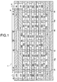
- Figs. 1-10 represent one embodiment of a reactor within the scope of this invention, wherein the reactor is composed of X-shaped reaction chambers.
- reactor 4 contains distribution flow-plates 12 and 24; reaction-chamber reactor plates 14, 16, 18, 20, and 22; and first and second end-plates E1 and E2.
- Flow-plates 12-24 are stacked adjacent to one another in a front-to-back facial configuration and sandwiched between the first and second end-plates.
- Reactor plates 14, 16, 18, 20 and 22 contain a series of X-shaped reaction chambers for reacting two or more components.
- Each reaction chamber contains two inlet-lobes for receiving two mutually separated fluid component streams; a first mixing zone for combining the two fluid component streams to form a single at least partially reacted multicomponent fluid stream; a flow-splitting means for splitting the single at least partially reacted multicomponent fluid stream into two at least partially reacted multicomponent fluid substreams; and two outlet-lobes through which the two at least partially reacted multicomponent fluid substreams exit the reaction chamber.
- Disposed in the first mixing zone is a heat-exchange port which extends through the thickness of the reactor plate.
- each reaction chamber in reactor 4 further contains a turbulence-inducing zone disposed upstream of and in fluid communication with the mixing zone. The turbulence-inducing zone in each reaction chamber is adapted to induce turbulence in the separated streams as the streams enter the first mixing zone. As a result, the streams undergo turbulent (and, therefore, more thorough) mixing in the first mixing zone of the reaction chamber.
- End-plate E1 and distribution flow plate 12 each contain a pair of inlet-ports for directing mutually separated fluid component streams to a first reaction chamber formed in first reactor plate 14.
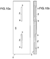
- end-plate E1 and distribution flow 12 each contain heat exchange ports 80 and 82 (end-plate E1) and heat exchange ports 12a, 12b, 12c and 12d (distribution flow plate 12) for directing a heat exchange fluid through heat exchange channel 78.
- Distribution flow-plates 12 and 24 each contain two separate distribution flow-channels which are adapted to receive component-fluid flow from one vertical series of reaction chambers and to direct the flow of the fluid to a second vertical series of reaction chambers.
- Distribution flow plate 24 also contains heat exchange ports 24a, 24b, 24c and 24d.
- the fluid then flows to outlet-side 90 of channel-section 78f and from there enters vertical channel-section 78c.
- Fluid H is then passed through channel-section 78c to a third horizontal channel-section 78g, formed in second end-plate E2, where the fluid enters channel-section 78g at inlet-side 92 and exits at outlet-side 94.
- fluid H then flows through vertical channel-section 78d to exit the reactor via outlet-port 82.
- the heat exchange fluid is then recirculated back into reactor 4 by means of an external channel, discussed hereinabove, which is disposed between outlet-port 82 and inlet-port 80.
- Reaction chamber 26 is composed of a turbulence-inducing zone 26c (shown in dashed lines); a first mixing zone 26d (shown in dotted lines); a heat exchange port 14a through which a section of heat exchange channel 78 is passed, port 14a being disposed in first mixing zone 26d; a flow-splitting member 26e; two outlet-lobes 26f and 26g; and two outlet-ports 108 and 110.
- the first and second fluid streams are passed from inlet-lobes 26a and 26b through turbulence-inducing zone 26c and first mixing zone 26d, where the streams undergo turbulent mixing to form a first at least partially reacted multicomponent stream (not shown). While the first and second streams undergo turbulent mixing in first mixing zone 26d, the streams are disposed in a heat exchange relationship with fluid H as the heat exchange fluid flows through the section of heat exchange channel 78 extending through port 14a in first mixing zone 26d. The first at least partially reacted multicomponent stream is then directed to flow-splitting member 26e which splits the stream into first and second at least partially reacted multicomponent substreams (not shown). The first and second substreams are then directed to respective outlet-lobes 26f and 26g, where the substreams exit chamber 26 via respective outlet-ports 108 and 110.
- the second at least partially reacted multicomponent stream is then directed to a flow-splitting member 34e which splits the stream into third and fourth at least partially reacted multicomponent substreams (not shown).
- the third and fourth substreams are then directed to respective outlet-lobes 34g and 34f, where the substreams exit chamber 34 via respective outlet-ports 116 and 114.
- the streams are disposed in a heat exchange relationship with fluid H as the heat exchange fluid flows through the section of heat exchange channel 78 extending through a heat exchange port 18a formed in first mixing zone 42d.
- the third at least partially reacted multicomponent stream is then directed to a flow-splitting member 42e which splits the stream into fifth and sixth at least partially reacted multicomponent substreams (not shown).
- the fifth and sixth substreams are then directed to respective outlet-lobes 42f and 42g, where the substreams exit chamber 42 via respective outlet-ports 120 and 122.
- the fifth and sixth substreams flow through respective outlet-ports 120 and 122 to respective inlet-lobes 50b and 50a of a reaction chamber 50 formed in a front facial surface 100F of plate 20.
- the fifth and sixth substreams are passed from respective inlet-lobes 50b and 50a through a turbulence-inducing zone 50c (shown in dashed lines) and a first mixing zone 50d (shown in dotted lines), where the streams undergo turbulent mixing to form a fourth at least partially reacted multicomponent stream (not shown).
- the streams are disposed in a heat exchange relationship with fluid H as the heat exchange fluid flows through the section of heat exchange channel 78 extending through a heat exchange port 20a disposed in first mixing zone 50d.
- the fourth at least partially reacted multicomponent stream is then directed to a flow-splitting member 50e which splits the stream into seventh and eighth at least partially reacted multicomponent substreams (not shown).
- the seventh and eighth substreams are then directed to respective outlet-lobes 50g and 50f, where the substreams exit chamber 50 via respective outlet-ports 128 and 126.
- the ninth substream flows to inlet-side 72a of a flow chamber 72 formed in a front facial surface 100H of plate 24.
- the tenth substream flows to inlet-side 70a of a flow chamber 70 formed in surface 100H of plate 24.
- the ninth and tenth substreams are respectfully directed to outlet-sides 72b and 70b of flow chambers 72 and 70.
- the ninth and tenth substreams are respectively directed through inlet-ports 142 and 140 in plate 22 to respective inlet-lobes 60b and 60a of a reaction chamber 60 formed in surface 100G of plate 22.
- the ninth and tenth substreams are passed from respective inlet-lobes 60b and 60a through a turbulence-inducing zone 60c (shown in dashed lines) and a first mixing zone 60d (shown in dotted lines), where the streams undergo turbulent mixing to form a sixth at least partially reacted multicomponent stream (not shown). While the ninth and tenth substreams undergo turbulent mixing in first mixing zone 60d, the streams are disposed in a heat exchange relationship with fluid H as the heat exchange fluid flows through the section of heat exchange channel 78 extending through a heat exchange port 22b disposed in first mixing zone 60d.
- the sixth at least partially reacted multicomponent stream is then directed to a flow-splitting member 60e which splits the stream into eleventh and twelfth at least partially reacted multicomponent substreams (not shown), which are then directed to respective outlet-lobes 60g and 60f.
- the eleventh and twelfth substreams are directed through respective inlet-ports 146 and 148 formed in plate 20 to respective inlet-lobes 52a and 52b of a reaction chamber 52 formed in surface 100F of plate 20.
- the eleventh and twelfth substreams are passed from respective inlet-lobes 52a and 52b through a turbulence-inducing zone 52c (shown in dashed lines) and a first mixing zone 52d (shown in dotted lines), where the streams undergo turbulent mixing to form a seventh at least partially reacted multicomponent stream (not shown).
- the streams are disposed in a heat exchange relationship with fluid H as the heat exchange fluid flows through the section of heat exchange channel 78 extending through a heat exchange port 20b disposed in first mixing zone 52d.
- the seventh at least partially reacted multicomponent stream is then directed to a flow-splitting member 52e which splits the stream into thirteenth and fourteenth at least partially reacted multicomponent substreams (not shown), which are then directed to respective outlet-lobes 52f and 52g.
- the thirteenth and fourteenth substreams are directed through respective inlet-ports 154 and 152 formed in plate 18 to respective inlet-lobes 44b and 44a of a reaction chamber 44 formed in surface 100E of plate 18.
- the thirteenth and fourteenth substreams are passed from respective inlet-lobes 44b and 44a through a turbulence-inducing zone 44c (shown in dashed lines) and a first mixing zone 44d (shown in dotted lines), where the streams undergo turbulent mixing to form an eighth at least partially reacted multicomponent stream (not shown).
- the streams are disposed in a heat exchange relationship with fluid H as the heat exchange fluid flows through the section of heat exchange channel 78 extending through a heat exchange port 18b formed in first mixing zone 44d.
- the eighth at least partially reacted multicomponent stream is then directed to a flow-splitting member 44e which splits the stream into fifteenth and sixteenth at least partially reacted multicomponent substreams (not shown), which are then directed to respective outlet-lobes 44g and 44f.
- the fifteenth and sixteenth substreams are directed through respective inlet-ports 158 and 160 formed in plate 16 to respective inlet-lobes 36a and 36b of a reaction chamber 36 formed in surface 100D of plate 16.
- the fifteenth and sixteenth substreams are passed from respective inlet-lobes 36a and 36b through a turbulence-inducing zone 36c (shown in dashed lines) and a first mixing zone 36d (shown in dotted lines), where the streams undergo turbulent mixing to form a ninth at least partially reacted multicomponent stream (not shown).
- the streams are disposed in a heat exchange relationship with fluid H as the heat exchange fluid flows through the section of heat exchange channel 78 extending through a heat exchange port 16b formed in first mixing zone 36d.
- the ninth at least partially reacted multicomponent stream is then directed to a flow-splitting member 36e which splits the stream into seventeenth and eighteenth at least partially reacted multicomponent substreams (not shown), which are then directed to respective outlet-lobes 36f and 36g.
- the fifteenth and sixteenth substreams are directed through respective inlet-ports 166 and 164 formed in plate 14 to respective inlet-lobes 28b and 28a of a reaction chamber 28 formed in surface 100C of plate 14.
- the seventeenth and eighteenth substreams are passed from respective inlet-lobes 28b and 28a through a turbulence-inducing zone 28c (shown in dashed lines) and a first mixing zone 28d (shown in dotted lines), where the streams undergo turbulent mixing to form a tenth at least partially reacted multicomponent stream (not shown).
- first mixing zone 28d While the seventeenth and eighteenth substreams undergo turbulent mixing in first mixing zone 28d, the streams are disposed in a heat exchange relationship with fluid H as the heat exchange fluid flows through the section of heat exchange channel 78 extending through a heat exchange port 14b formed in first mixing zone 28d.
- the tenth at least partially reacted multicomponent stream is then directed to a flow-splitting member 28e which splits the stream into nineteenth and twentieth at least partially reacted multicomponent substreams (not shown), which are then directed to respective outlet-lobes 28g and 28f.
- the nineteenth and twentieth substreams are directed to respective inlet-sides 66a and 68a of flow chambers 66 and 68 formed in surface 100B of plate 12. From inlet-sides 66a and 68a, the nineteenth and twentieth substreams flow to respective outlet-sides 66b and 68b of flow chambers 66 and 68.
- the nineteenth and twentieth substreams flow to respective inlet-lobes 30a and 30b of a reaction chamber 30 formed in surface 100C of plate 14.
- the nineteenth and twentieth substreams are passed from respective inlet-lobes 30a and 30b through a turbulence-inducing zone 30c and a first mixing zne 30d, where the streams undergo turbulent mixing to form an eleventh at least partially reacted multicomponent stream (not shown). While the nineteenth and twentieth substreams undergo turbulent mixing in first mixing zone 30d, the streams are disposed in a heat exchange relationship with fluid H as the heat exchange fluid flows through the section of heat exchange channel 78 extending through a heat exchange port 14c formed in first mixing zone 30d.
- the eleventh at least partially reacted multicomponent stream is then directed to a flow-splitting member 30e which splits the stream into twenty-first and twenty-second at least partially reacted multicomponent substreams (not shown), which are then directed to respective outlet-lobes 30f and 30g, where the streams exit chamber 30 via respective outlet-ports 168 and 170.
- the twenty-first and twenty-second substreams are directed to respective inlet-lobes 38b and 38a of a reaction chamber 38 formed in surface 100D of plate 16.
- the twenty-first and twenty-second substreams are passed from respective inlet-lobes 38b and 38a through a turbulence-inducing zone 38c (shown in dashed lines) and a first mixing zone 38d (shown in dotted lines), where the streams undergo turbulent mixing to form a twelfth at least partially reacted multicomponent stream (not shown). While the twenty-first and twenty-second substreams undergo turbulent mixing in first mixing zone 38d, the streams are disposed in a heat exchange relationship with fluid H as the heat exchange fluid flows through the section of heat exchange channel 78 extending through a heat exchange port 16c formed in first mixing zone 38d.
- the twelfth at least partially reacted multicomponent stream is then directed to a flow-splitting member 38e which splits the stream into twenty-third and twenty-fourth at least partially reacted multicomponent substreams (not shown), which are then directed to respective outlet-lobes 38g and 38f.
- the twenty-third and twenty-fourth substreams are directed to respective inlet-lobes 46a and 46b of a reaction chamber 46 formed in surface 100E of plate 18.
- the twenty-third and twenty-fourth substreams are passed from respective inlet-lobes 46a and 46b through a turbulence-inducing zone 46c (shown in dashed lines) and a first mixing zone 46d (shown in dotted lines), where the streams undergo turbulent mixing to form a thirteenth at least partially rreacted multicomponent stream (not shown).
- first mixing zone 46d While the twenty-third and twenty-fourth substreams undergo turbulent mixing in first mixing zone 46d, the streams are disposed in a heat exchange relationship with fluid H as the heat exchange fluid flows through the section of heat exchange channel 78 extending through a heat exchange port 18c formed in first mixing zone 46d.
- the thirteenth at least partially reacted multicomponent stream is then directed to a flow-splitting member 46e which splits the stream into twenty-fifth and twenty-sixth at least partially reacted multicomponent substreams (not shown), which are then directed to respective outlet-lobes 46f and 46g.
- the twenty-fifth and twenty-sixth substreams are directed to respective inlet-lobes 54b and 54a of a reaction chamber 54 formed in surface 100F of plate 20.
- the twenty-fifth and twenty-sixth substreams are passed from respective inlet-lobes 54b and 54a through a turbulence-inducing zone 54c (shown in dashed lines) and a first mixing zone 54d (shown in dotted lines), where the streams undergo turbulent mixing to form a fourteenth at least partially reacted multicomponent stream (not shown).
- the streams are disposed in a heat exchange relationship with fluid H as the heat exchange fluid flows through the section of heat exchange channel 78 extending through heat exchange port 20c disposed in first mixing zone 54d.
- the fourteenth at least partially reacted multicomponent stream is then directed to a flow-splitting member 54e which splits the stream into twenty-seventh and twenty-eighth at least partially reacted multicomponent substreams (not shown), which are then directed to respective outlet-lobes 54g and 54f.
- first mixing zone 62d While the twenty-seventh and twenty-eighth substreams undergo turbulent mixing in first mixing zone 62d, the streams are disposed in a heat exchange relationship with fluid H as the heat exchange fluid flows through the section of heat exchange channel 78 extending through a heat exchange port 22c formed in first mixing zone 62d.
- the fifteenth at least partially reacted multicomponent stream is then directed to a flow-splitting member 62e which splits the stream into twenty-ninth and thirtieth at least partially reacted multicomponent substreams (not shown), which are then directed to respective outlet-lobes 62f and 62g.
- the twenty-ninth and thirtieth substreams flow to inlet-sides 76a and 74a of respective flow chambers 76 and 74 formed in surface 100H of plate 24.
- the substreams flow to respective outlet-sides 76b and 74b in chambers 76 and 74, and from these outlet-sides, the substreams are directed through inlet-ports 198 and 196 formed in plate 22 to respective inlet-lobes 64b and 64a of a reaction chamber 64 formed in surface 100G of plate 22.
- the twenty-ninth and thirtieth substreams are passed from respective inlet-lobes 64b and 64a through a turbulence-inducing zone 64c (shown in dashed lines) and a first mixing zone 64d (shown in dotted lines), where the streams undergo turbulent mixing to form a sixteenth at least partially reacted multicomponent stream (not shown). While the twenty-ninth and thirtieth substreams undergo turbulent mixing in first mixing zone 64d, the streams are disposed in a heat exchange relationship with fluid H as the heat exchange fluid flows through the section of heat exchange channel 78 extending through a heat exchange port 22d disposed in first mixing zone 64d.
- the sixteenth at least partially reacted multicomponent stream is then directed to a flow-splitting member 64e which splits the stream into thirty-first and thirty-second at least partially reacted multicomponent substreams (not shown), which are then directed to respective outlet-lobes 64g and 64f.
- the thirty-first and thirty-second substreams are directed from outlet-lobes 64g and 64f via inlet-ports 212 and 214 formed in plate 20 to respective inlet-lobes 56a and 56b of a reaction chamber 56 formed in surface 100F of plate 20.
- the thirty-first and thirty-second substreams are passed from respective inlet-lobes 56a and 56b through a turbulence-inducing zone 56c (shown in dashed lines) and a first mixing zone 56d (shown in dotted lines), where the streams undergo turbulent mixing to form a seventeenth at least partially reacted multicomponent stream (not shown).
- the streams are disposed in a heat exchange relationship with fluid H as the heat exchange fluid flows through the section of heat exchange channel 78 extending through a heat exchange port 20d disposed in first mixing zone 56d.
- the seventeenth at least partially reacted multicomponent stream is then directed to a flow-splitting member 56e which splits the stream into thirty-third and thirty-fourth at least partially reacted multicomponent substreams (not shown), which are then directed to respective outlet-lobes 56f and 56g.
- the thirty-third and thirty-fourth substreams are directed from outlet-lobes 56f and 56g via inlet-ports 220 and 218 formed in plate 18 to respective inlet-lobes 48b and 48a of a reaction chamber 48 formed in surface 100E of plate 18.
- the thirty-third and thirty-fourth substreams are passed from respective inlet-lobes 48b and 48a through a turbulence-inducing zone 48c (shown in dashed lines) and a first mixing zone 48d (shown in dotted lines), where the streams undergo turbulent mixing to form an eighteenth at least partially reacted multicomponent stream (not shown).
- the streams are disposed in a heat exchange relationship with fluid H as the heat exchange fluid flows through the section of heat exchange channel 78 extending through a heat exchange port 18d disposed in the first mixing zone 48d.
- the eighteenth at least partially reacted multicomponent stream is then directed to a flow-splitting member 48e which splits the stream into thirty-fifth and thirty-sixth at least partially reacted multicomponent substreams (not shown), which are then directed to respective outlet-lobes 48g and 48f.
- the thirty-fifth and thirty-sixth substreams are directed from outlet-lobes 48g and 48f via inlet-ports 224 and 226 formed in plate 16 to respective inlet-lobes 40a and 40b of a reaction chamber 40 formed in surface 100D of plate 16.
- the thirty-fifth and thirty-sixth substreams are passed from respective inlet-lobes 40a and 40b through a turbulence-inducing zone 40c (shown in dashed lines) and a first mixing zone 40d (shown in dashed lines), where the streams undergo turbulent mixing to form a nineteenth at least partially reacted multicomponent stream (not shown).
- the streams are disposed in a heat exchange relationship with fluid H as the heat exchange fluid flows through the section of heat exchange channel 78 extending through a heat exchange port 16d disposed in first mixing zone 40d.
- the nineteenth at least partially reacted multicomponent stream is then directed to a flow-splitting member 40e which splits the stream into thirty-seventh and thirty-eighth at least partially reacted multicomponent substreams (not shown), which are then directed to respective outlet-lobes 40f and 40g.
- the streams are disposed in a heat exchange relationship with fluid H as the heat exchange fluid flows through the section of heat exchange channel 78 extending through a heat exchange port 14d formed in first mixing zone 32d.
- the twentieth at least partially reacted multicomponent stream is then directed to a flow-splitting member 32e which splits the stream into a thirty-ninth at least partially reacted multicomponent substream (not shown) and a fortieth at least partially reacted multicomponent substream "S-40", which are then directed to respective outlet-lobes 32g and 32f.
- Plate stack 300 is composed of distribution flow plate 302, and reaction-chamber reactor plates 304 and 308, and flow-separation reactor plate 306.
- Plates 304 and 308 each contain a plurality of reaction chambers.
- Plate 302 (having facial surface 302A shown in Fig. 12a) contains ports for directing fluid streams to plate 304.
- Plate 306 contains a plurality of flow-separation chambers.
- a heat exchange channel would preferably pass through through-holes formed in the first mixing zones of the reaction chambers shown in these figures.
- Two component fluid streams may be directed through reactor 300 as follows. First and second fluid streams (not shown), each containing at least one component, may be introduced into reactor 300 via respective inlet-ports 310 and 312 formed in plate 302. Through inlet-ports 310 and 312, the streams are then passed to respective inlet-ends 318a and 318b of a reaction chamber 318 (shown in Fig. 13b and composed of 318a-318e) formed in a front facial surface 304A of plate 304.
- the streams are then combined at a first mixing zone 318c of chamber 318 to form a first multicomponent stream (not shown), which is then passed through flow-channel 318d to outlet-end 318e, where the first multicomponent stream exits chamber 318 via outlet-port 320.
- the first and second substreams are directed to respective inlet-ends 330a and 330b of a reaction chamber 330 formed in a front facial surface 308A of plate 308.
- the streams are then combined at first mixing zone 330c of chamber 330 to form a second multicomponent stream (not shown), which is then passed through flow-channel 330d to outlet-end 330e.
- the second multicomponent stream is directed to flow-splitting region 334c of a reaction chamber 334 formed in surface 306A of plate 306.
- the stream is split at region 334c into third and fourth multicomponent substreams (not shown), which are then directed to respective outlet-ends
- the third and fourth substreams are directed through respective inlet-ports 338 and 340 formed in plate 304 to respective inlet-ends 336a and 336b of a reaction chamber 336 (shown in Fig. 13b and composed of 336a-336e) formed in surface 304A of plate 304.
- the third and fourth substreams are then combined at first mixing zone 336c to form a third multicomponent stream (not shown), which is then directed through flow-channel 336d to outlet-end 336e of chamber 336.
- the third multicomponent stream exits chamber 336 via outlet-port 342 formed in outlet-end 336e.
- the third multicomponent stream flows into flow-splitting region 346a of a flow-separation chamber 346 formed in surface 306A of plate 306.
- the third multicomponent stream is split at region 346a into fifth and sixth multicomponent substreams (not shown), which are then directed to respective outlet-ends 346b and 346c of chamber 346.
- the fifth and sixth substreams exit chamber 346 via respective outlet-ports 348 and 350 formed in outlet-ends 346b and 346c.
- the fifth and sixth substreams are directed into respective inlet-ends 354a and 354b of a reaction chamber 354 formed in surface 308A of plate 308.
- the substreams are then combined at first mixing zone 354c to form a fourth multicomponent stream (not shown), which is then directed through flow-channel 354d to outlet-end 354e of chamber 354.
- the fourth multicomponent stream is directed through inlet-port 358 formed in plate 306 to a flow-splitting region 360c of a reaction chamber 360 formed in surface 306A of plate 306.
- the fourth multicomponent stream is split at region 360c into seventh and eighth multicomponent substreams (not shown), which are then directed to respective outlet-ends 360a and 360b.
- the seventh and eighth substreams are directed through respective inlet-ports 366 and 368 formed in plate 304 to respective inlet-ends 370a and 370b of a reaction chamber 370 (shown in Fig. 13b and composed of 370a-e) formed in surface 304A of plate 304.
- the seventh and eighth substreams are combined at first mixing zone 370c of chamber 370 to form a fifth multicomponent stream (not shown), which is then directed through flow-channel 370d to outlet-end 370e.
- the fifth multicomponent stream exits chamber 370 via outlet-port 371 formed in outlet-end 370e.
- the fifth multicomponent stream flows to flow-splitting region 372a of a flow-separation chamber composed of regions 372a-372c formed in surface 306A of plate 306.
- the fifth multicomponent stream is split at region 372a into ninth and tenth multicomponent substreams (not shown), which are then directed to respective outlet-ends 372b and 372c.
- the ninth and tenth substreams exit chamber 372 via respective outlet-ports 374 and 376.
- the ninth and tenth substreams are directed to respective inlet-ends 378a and 378b of a reaction chamber 378 formed in surface 308A of plate 308.
- the ninth and tenth substreams are combined at first mixing zone 378c of chamber 378 to form a sixth multicomponent stream (not shown).
- the sixth multicomponent stream is then directed through flow-channel 378d to outlet-end 378e of chamber 378.
- the sixth multicomponent stream is directed through inlet-port 380 formed in plate 306 to a flow-splitting region 382c of a reaction chamber 382 formed in surface 306A of plate 306.
- the sixth multicomponent stream is split at region 382c into eleventh and twelfth multicomponent substreams (not shown), which are then directed to respective outlet-ends 382a and 382b of chamber 382.
- the eleventh and twelfth substreams are directed through respective inlet-ports 384 and 386 formed in plate 304 to respective inlet-ends 388a and 388b of a reaction chamber 388 (shown in Fig. 13b and composed of 388a-388e) formed in surface 304A of plate 304.
- the eleventh and twelfth substreams are then combined at first mixing zone 388c of chamber 388 to form a seventh multicomponent stream (not shown).
- the seventh multicomponent stream is then directed through flow-channel 388d to outlet-end 388e, from which the stream exits chamber 388 via outlet-port 390.
- the seventh multicomponent stream flows to flow-splitting region 394a of a flow-separation chamber 394 formed in surface 306A of plate 306.
- the seventh multicomponent stream is split at region 394a into thirteenth and fourteenth multicomponent fluid substreams (not shown), which are then directed to outlet-ends 394b and 394c of chamber 394.
- the thirteenth and fourteenth substreams exit chamber 394 via respective outlet-ports 396 and 398.
- the thirteenth and fourteenth substreams are directed into respective inlet-ends 402a and 402b of a reaction chamber 402 formed in surface 308A of plate 308.
- the substreams are combined at first mixing zone 402c of chamber 402 to form an eighth multicomponent stream (not shown).
- the eighth multicomponent stream is then directed through flow-channel 402d to outlet-end 402e of chamber 402.
- the eighth multicomponent stream is directed through inlet-port 406 formed in plate 306 to a flow-splitting region 408c of a flow-separation chamber 408 formed in surface 306A of plate 306.
- the eighth multicomponent stream is split at region 408c into fifteenth and sixteenth multicomponent substreams (not shown), which are then directed to outlet-ends 408a and 408b, respectively.
- the fifteenth and sixteenth substreams are directed through respective inlet-ports 414 and 416 formed in plate 304 to respective inlet-ends 418a and 418b of a reaction chamber 418 (shown in Fig. 13b and composed of 418a-418e) formed in surface 304A of plate 304.
- the substreams are then combined at first mixing zone 418c of chamber 418 to form a ninth multicomponent stream (not shown).
- the ninth multicomponent stream is then directed through flow-channel 418d to outlet-end 418e of chamber 418.
- the ninth multicomponent stream is directed through outlet-port 422 formed in plate 302. From outlet-port 422, the ninth multicomponent stream can be directed out of reactor 300 to a desired location.
Landscapes
- Chemical & Material Sciences (AREA)
- Chemical Kinetics & Catalysis (AREA)
- Organic Chemistry (AREA)
- Dispersion Chemistry (AREA)
- Physical Or Chemical Processes And Apparatus (AREA)
Applications Claiming Priority (2)
| Application Number | Priority Date | Filing Date | Title |
|---|---|---|---|
| US503771 | 1995-07-18 | ||
| US08/503,771 US5658537A (en) | 1995-07-18 | 1995-07-18 | Plate-type chemical reactor |
Publications (3)
| Publication Number | Publication Date |
|---|---|
| EP0754492A2 true EP0754492A2 (de) | 1997-01-22 |
| EP0754492A3 EP0754492A3 (de) | 1997-09-03 |
| EP0754492B1 EP0754492B1 (de) | 2000-09-27 |
Family
ID=24003442
Family Applications (1)
| Application Number | Title | Priority Date | Filing Date |
|---|---|---|---|
| EP96110781A Expired - Lifetime EP0754492B1 (de) | 1995-07-18 | 1996-07-04 | Chemischer Plattenreaktor |
Country Status (5)
| Country | Link |
|---|---|
| US (2) | US5658537A (de) |
| EP (1) | EP0754492B1 (de) |
| CA (1) | CA2176432C (de) |
| DE (1) | DE69610467T2 (de) |
| MX (1) | MX9601969A (de) |
Cited By (6)
| Publication number | Priority date | Publication date | Assignee | Title |
|---|---|---|---|---|
| WO1999016542A1 (en) * | 1997-09-26 | 1999-04-08 | Battelle Memorial Institute | Microchannel laminated mass exchanger and method of making |
| EP1030733A4 (de) * | 1997-02-05 | 2000-08-30 | California Inst Of Techn | Mikromischer für den unter-millisekunden-arbeitsbereich |
| US6192596B1 (en) | 1999-03-08 | 2001-02-27 | Battelle Memorial Institute | Active microchannel fluid processing unit and method of making |
| WO2007050013A1 (en) * | 2005-10-24 | 2007-05-03 | Alfa Laval Corporate Ab | Multipurpose flow module |
| US7332139B2 (en) | 2000-08-31 | 2008-02-19 | Degussa Ag | Process and device for carrying out reactions in reactor with slot-shaped reaction spaces |
| US7883670B2 (en) | 2002-02-14 | 2011-02-08 | Battelle Memorial Institute | Methods of making devices by stacking sheets and processes of conducting unit operations using such devices |
Families Citing this family (82)
| Publication number | Priority date | Publication date | Assignee | Title |
|---|---|---|---|---|
| US5851636A (en) * | 1995-12-29 | 1998-12-22 | Lantec Products, Inc. | Ceramic packing with channels for thermal and catalytic beds |
| DE19708472C2 (de) * | 1997-02-20 | 1999-02-18 | Atotech Deutschland Gmbh | Herstellverfahren für chemische Mikroreaktoren |
| US6036927A (en) * | 1997-07-22 | 2000-03-14 | Eastman Kodak Company | Micro-ceramic chemical plant having catalytic reaction chamber |
| US5976472A (en) * | 1997-10-15 | 1999-11-02 | Eastman Kodak Company | Integrated micro-ceramic chemical plant with insertable catalytic reaction chambers |
| US5965092A (en) * | 1997-10-15 | 1999-10-12 | Eastman Kodak Company | Integrated micro-ceramic chemical plant with insertable micro-filters |
| US5961930A (en) * | 1997-10-15 | 1999-10-05 | Eastman Kodak Company | Integrated micro-ceramic chemical plant with insertable reaction chambers and micro-filters |
| WO1999040771A2 (en) | 1998-02-13 | 1999-08-19 | Selective Genetics, Inc. | Concurrent flow mixing for preparing compositions comprising gene therapy vectors |
| US8173431B1 (en) | 1998-11-13 | 2012-05-08 | Flir Systems, Inc. | Mail screening to detect mail contaminated with biological harmful substances |
| US6749814B1 (en) | 1999-03-03 | 2004-06-15 | Symyx Technologies, Inc. | Chemical processing microsystems comprising parallel flow microreactors and methods for using same |
| US7150994B2 (en) * | 1999-03-03 | 2006-12-19 | Symyx Technologies, Inc. | Parallel flow process optimization reactor |
| US6451268B1 (en) * | 1999-04-16 | 2002-09-17 | Minerals Technologies Inc. | Method and apparatus for continuous gas liquid reactions |
| US6572828B1 (en) | 1999-07-16 | 2003-06-03 | General Electric Company | Method and apparatus for high-throughput chemical screening |
| US6770482B1 (en) * | 1999-07-16 | 2004-08-03 | General Electric | Method and apparatus for rapid screening of multiphase reactions |
| US6379626B1 (en) | 1999-09-03 | 2002-04-30 | Array Biopharma | Reactor plate clamping system |
| US6403379B1 (en) | 1999-09-03 | 2002-06-11 | Array Biopharma | Reactor plate washing station |
| US7041260B1 (en) | 1999-10-19 | 2006-05-09 | Mesosystems Technology, Inc. | Integral compact heat exchanger and catalytic reactor for scavenging contaminants from air |
| US6932951B1 (en) | 1999-10-29 | 2005-08-23 | Massachusetts Institute Of Technology | Microfabricated chemical reactor |
| US20020119079A1 (en) * | 1999-12-10 | 2002-08-29 | Norbert Breuer | Chemical microreactor and microreactor made by process |
| US6441109B1 (en) | 1999-12-30 | 2002-08-27 | Basf Corporation | Continuous polymerization and direct fiber spinning and apparatus for accomplishing same |
| US6392007B1 (en) | 1999-12-30 | 2002-05-21 | Basf Corporation | Multi-pixel liquid streams, especially fiber-forming polymeric streams, and methods and apparatus for forming same |
| US7056477B1 (en) * | 2000-02-03 | 2006-06-06 | Cellular Process Chemistry, Inc. | Modular chemical production system incorporating a microreactor |
| DE50107530D1 (de) * | 2000-02-14 | 2006-02-09 | Cpc Cellular Process Chemistry | Mikroreaktor mit verbessertem Wärmetauscher |
| DE60108482T2 (de) | 2000-03-07 | 2006-02-16 | Symyx Technologies, Inc., Santa Clara | Prozessoptimierungsreaktor mit parallelem durchfluss |
| US7302998B2 (en) * | 2000-06-08 | 2007-12-04 | Mikros Manufacturing, Inc. | Normal-flow heat exchanger |
| WO2002055942A2 (en) * | 2000-06-08 | 2002-07-18 | Mikros Manufacturing, Inc. | Normal-flow heat exchanger |
| US6935411B2 (en) * | 2000-06-08 | 2005-08-30 | Mikros Manufacturing, Inc. | Normal-flow heat exchanger |
| US7413714B1 (en) | 2000-07-16 | 2008-08-19 | Ymc Co. Ltd. | Sequential reaction system |
| DE10036602A1 (de) * | 2000-07-27 | 2002-02-14 | Cpc Cellular Process Chemistry | Mikroreaktor für Reaktionen zwischen Gasen und Flüssigkeiten |
| US6623860B2 (en) * | 2000-10-10 | 2003-09-23 | Aclara Biosciences, Inc. | Multilevel flow structures |
| GB0030201D0 (en) * | 2000-12-12 | 2001-01-24 | Chart Heat Exchangers Ltd | Heat exchanger |
| DE10102726A1 (de) * | 2001-01-22 | 2002-08-22 | Vodafone Pilotentwicklung Gmbh | Reaktor |
| US7118917B2 (en) | 2001-03-07 | 2006-10-10 | Symyx Technologies, Inc. | Parallel flow reactor having improved thermal control |
| JP3694877B2 (ja) * | 2001-05-28 | 2005-09-14 | 株式会社山武 | マイクロ混合器 |
| CA2449724C (en) * | 2001-06-06 | 2011-03-15 | Battelle Memorial Institute | Fluid processing device and method |
| US6939632B2 (en) * | 2001-08-06 | 2005-09-06 | Massachusetts Institute Of Technology | Thermally efficient micromachined device |
| US7278474B2 (en) * | 2001-10-09 | 2007-10-09 | Mikros Manufacturing, Inc. | Heat exchanger |
| US20040047767A1 (en) * | 2002-09-11 | 2004-03-11 | Richard Bergman | Microfluidic channel for band broadening compensation |
| US6955777B2 (en) * | 2003-01-07 | 2005-10-18 | International Business Machines Corporation | Method of forming a plate for dispensing chemicals |
| JP4352704B2 (ja) * | 2003-01-09 | 2009-10-28 | 日産自動車株式会社 | 一酸化炭素除去装置 |
| DE10318061A1 (de) * | 2003-04-17 | 2004-10-28 | Behr Gmbh & Co. Kg | Mischvorrichtung |
| US20050069462A1 (en) * | 2003-09-30 | 2005-03-31 | International Business Machines Corporation | Microfluidics Packaging |
| US20050069949A1 (en) * | 2003-09-30 | 2005-03-31 | International Business Machines Corporation | Microfabricated Fluidic Structures |
| US20050077657A1 (en) * | 2003-10-14 | 2005-04-14 | International Business Machines Corporation | A Method of Making a Multichannel and Multilayer Pharmaceutical Device |
| US6994245B2 (en) * | 2003-10-17 | 2006-02-07 | James M. Pinchot | Micro-reactor fabrication |
| US20050084072A1 (en) * | 2003-10-17 | 2005-04-21 | Jmp Industries, Inc., An Ohio Corporation | Collimator fabrication |
| US8066955B2 (en) * | 2003-10-17 | 2011-11-29 | James M. Pinchot | Processing apparatus fabrication |
| DE102004001852A1 (de) * | 2004-01-13 | 2005-08-04 | Syntics Gmbh | Verfahren und Vorrichtung zum Mischen wenigstens zweier Fluide in einer Mikrostruktur |
| DE102004013551A1 (de) * | 2004-03-19 | 2005-10-06 | Goldschmidt Gmbh | Alkoxylierungen in mikrostrukturierten Kapillarreaktoren |
| US7645423B2 (en) * | 2004-08-20 | 2010-01-12 | International Business Machines Corporation | Optical micro plugs for multichannel and multilayer pharmaceutical device |
| US20060046113A1 (en) * | 2004-08-31 | 2006-03-02 | Sarnoff Corporation | Stacked reactor with microchannels |
| JP2008539090A (ja) * | 2005-04-26 | 2008-11-13 | アビザ テクノロジー リミティド | マイクロ流体構造およびその製造方法 |
| EP1888213B1 (de) * | 2005-05-25 | 2017-10-18 | Bio-Rad Laboratories, Inc. | Fluidvorrichtung |
| US20060272713A1 (en) * | 2005-05-31 | 2006-12-07 | Garner Sean M | Microfluidic devices with integrated tubular structures |
| US20070137607A1 (en) * | 2005-12-19 | 2007-06-21 | Ledbetter Kelly B | Cylinder block mounted two-pass oil cooler |
| DE102006013503A1 (de) * | 2006-03-23 | 2008-01-24 | Esk Ceramics Gmbh & Co. Kg | Plattenwärmetauscher, Verfahren zu dessen Herstellung und dessen Verwendung |
| EP2104755A4 (de) * | 2006-10-26 | 2011-01-12 | Symyx Solutions Inc | Hochdruck-parallel-festbettreaktor und verfahren dafür |
| US7862633B2 (en) * | 2007-04-13 | 2011-01-04 | Battelle Memorial Institute | Method and system for introducing fuel oil into a steam reformer with reduced carbon deposition |
| WO2009023314A2 (en) | 2007-05-09 | 2009-02-19 | Icx Technologies | Mail parcel screening using multiple detection technologies |
| JP4466682B2 (ja) * | 2007-05-28 | 2010-05-26 | 株式会社日立プラントテクノロジー | 流体混合装置 |
| CN101909730B (zh) * | 2008-01-10 | 2013-07-10 | 株式会社盛长 | 静止型流体混合装置 |
| JP5500575B2 (ja) * | 2008-06-16 | 2014-05-21 | アイセル株式会社 | 混合要素、混合装置、混合方法、攪拌翼、攪拌装置及び攪拌方法 |
| US20100068404A1 (en) * | 2008-09-18 | 2010-03-18 | Guardian Industries Corp. | Draw-off coating apparatus for making coating articles, and/or methods of making coated articles using the same |
| US20100081577A1 (en) * | 2008-09-30 | 2010-04-01 | Symyx Technologies, Inc. | Reactor systems and methods |
| US8243274B2 (en) * | 2009-03-09 | 2012-08-14 | Flir Systems, Inc. | Portable diesel particulate monitor |
| US9589692B2 (en) | 2010-12-17 | 2017-03-07 | Palo Alto Research Center Incorporated | Interdigitated electrode device |
| US9004001B2 (en) | 2010-12-17 | 2015-04-14 | Palo Alto Research Center Incorporated | Interdigitated finger coextrusion device |
| US9590232B2 (en) | 2012-12-27 | 2017-03-07 | Palo Alto Research Center Incorporated | Three dimensional co-extruded battery electrodes |
| US9899669B2 (en) | 2012-12-27 | 2018-02-20 | Palo Alto Research Center Incorporated | Structures for interdigitated finger co-extrusion |
| US10923714B2 (en) | 2012-12-27 | 2021-02-16 | Palo Alto Research Center Incorporated | Structures for interdigitated finger co-extrusion |
| US9337471B2 (en) | 2012-12-27 | 2016-05-10 | Palo Alto Research Center Incorporated | Co-extrusion print head for multi-layer battery structures |
| US9012090B2 (en) | 2012-12-27 | 2015-04-21 | Palo Alto Research Center Incorporated | Advanced, high power and energy battery electrode manufactured by co-extrusion printing |
| US10046303B2 (en) | 2013-04-26 | 2018-08-14 | Corning Incorporated | Disassemblable stacked flow reactor |
| US10800086B2 (en) | 2013-08-26 | 2020-10-13 | Palo Alto Research Center Incorporated | Co-extrusion of periodically modulated structures |
| JP6115959B2 (ja) * | 2013-12-11 | 2017-04-19 | 株式会社フィルテック | 流体熱交換装置 |
| US9882200B2 (en) | 2014-07-31 | 2018-01-30 | Palo Alto Research Center Incorporated | High energy and power Li-ion battery having low stress and long-term cycling capacity |
| US9943819B2 (en) | 2014-11-03 | 2018-04-17 | Singh Instrument LLC | Small-scale reactor having improved mixing |
| US20160322131A1 (en) | 2015-04-29 | 2016-11-03 | Palo Alto Research Center Incoporated | Co-extrusion printing of filaments for superconducting wire |
| US9755221B2 (en) | 2015-06-26 | 2017-09-05 | Palo Alto Research Center Incorporated | Co-extruded conformal battery separator and electrode |
| NL2016066B1 (en) * | 2016-01-07 | 2017-07-13 | R&R Mechatronics Int B V | Apparatus for preparing a diluted sample fluid. |
| CN109464973B (zh) * | 2018-12-19 | 2024-03-08 | 上海璨谊生物科技有限公司 | 微通道模块 |
| CN109847666B (zh) * | 2019-01-18 | 2021-06-08 | 杭州沈氏节能科技股份有限公司 | 一种微通道反应组件及微通道反应器 |
| DE102019213645A1 (de) * | 2019-09-09 | 2021-03-11 | La Prairie Group Ag | Mischvorrichtung für Kosmetika |
Citations (4)
| Publication number | Priority date | Publication date | Assignee | Title |
|---|---|---|---|---|
| US3528783A (en) | 1964-06-16 | 1970-09-15 | Marston Excelsior Ltd | Multilayer catalytic reactor |
| US4421162A (en) | 1982-06-25 | 1983-12-20 | The Dow Chemical Company | Flat plate heat exchange apparatus |
| US4933242A (en) | 1989-02-28 | 1990-06-12 | Ishikawajima-Harima Heavy Industries Co., Ltd. | Power generation system with use of fuel cell |
| US5209906A (en) | 1991-05-10 | 1993-05-11 | Her Majesty The Queen In Right Of Canada, As Represented By The Minister Of National Defence | Modular isothermal reactor |
Family Cites Families (15)
| Publication number | Priority date | Publication date | Assignee | Title |
|---|---|---|---|---|
| US3881701A (en) * | 1973-09-17 | 1975-05-06 | Aerojet General Co | Fluid mixer reactor |
| US3856270A (en) * | 1973-10-09 | 1974-12-24 | Fmc Corp | Static fluid mixing apparatus |
| FR2348458A1 (fr) * | 1976-04-12 | 1977-11-10 | Commissariat Energie Atomique | Echangeur de chaleur a plaques |
| US4096910A (en) * | 1976-10-28 | 1978-06-27 | General Electric Company | Concentric-tube stacked plate heat exchanger |
| US4327802A (en) * | 1979-06-18 | 1982-05-04 | Borg-Warner Corporation | Multiple fluid heat exchanger |
| US4516632A (en) * | 1982-08-31 | 1985-05-14 | The United States Of America As Represented By The United States Deparment Of Energy | Microchannel crossflow fluid heat exchanger and method for its fabrication |
| CA1265289A (en) * | 1985-12-16 | 1990-01-30 | Viney Pal Aneja | Method and apparatus for devolatilizing polymer solutions |
| SE458884B (sv) * | 1987-05-29 | 1989-05-16 | Alfa Laval Thermal Ab | Permanent sammanfogad plattvaermevaexlare med sammanhaallande organ vid portarna |
| US4872578A (en) * | 1988-06-20 | 1989-10-10 | Itt Standard Of Itt Corporation | Plate type heat exchanger |
| DE3926466C2 (de) * | 1989-08-10 | 1996-12-19 | Christoph Dipl Ing Caesar | Mikroreaktor zur Durchführung chemischer Reaktionen von zwei chemischen Stoffen mit starker Wärmetönung |
| US5016707A (en) * | 1989-12-28 | 1991-05-21 | Sundstrand Corporation | Multi-pass crossflow jet impingement heat exchanger |
| GB9104156D0 (en) * | 1991-02-27 | 1991-04-17 | Rolls Royce & Ass | Heat exchanger |
| DE69413012T2 (de) * | 1993-03-19 | 1999-03-25 | Du Pont | Integrierte vorrichtung für chemische verfahrensschritte und herstellungsverfahren dafür |
| US5534328A (en) * | 1993-12-02 | 1996-07-09 | E. I. Du Pont De Nemours And Company | Integrated chemical processing apparatus and processes for the preparation thereof |
| US5595712A (en) * | 1994-07-25 | 1997-01-21 | E. I. Du Pont De Nemours And Company | Chemical mixing and reaction apparatus |
-
1995
- 1995-07-18 US US08/503,771 patent/US5658537A/en not_active Expired - Lifetime
-
1996
- 1996-05-13 CA CA002176432A patent/CA2176432C/en not_active Expired - Fee Related
- 1996-05-24 MX MX9601969A patent/MX9601969A/es not_active IP Right Cessation
- 1996-07-04 EP EP96110781A patent/EP0754492B1/de not_active Expired - Lifetime
- 1996-07-04 DE DE69610467T patent/DE69610467T2/de not_active Expired - Fee Related
-
1997
- 1997-04-02 US US08/831,869 patent/US5843385A/en not_active Expired - Fee Related
Patent Citations (4)
| Publication number | Priority date | Publication date | Assignee | Title |
|---|---|---|---|---|
| US3528783A (en) | 1964-06-16 | 1970-09-15 | Marston Excelsior Ltd | Multilayer catalytic reactor |
| US4421162A (en) | 1982-06-25 | 1983-12-20 | The Dow Chemical Company | Flat plate heat exchange apparatus |
| US4933242A (en) | 1989-02-28 | 1990-06-12 | Ishikawajima-Harima Heavy Industries Co., Ltd. | Power generation system with use of fuel cell |
| US5209906A (en) | 1991-05-10 | 1993-05-11 | Her Majesty The Queen In Right Of Canada, As Represented By The Minister Of National Defence | Modular isothermal reactor |
Cited By (14)
| Publication number | Priority date | Publication date | Assignee | Title |
|---|---|---|---|---|
| US6352577B1 (en) | 1994-07-29 | 2002-03-05 | Battelle Memorial Institute | Microchannel laminated mass exchanger and method of making |
| US6129973A (en) * | 1994-07-29 | 2000-10-10 | Battelle Memorial Institute | Microchannel laminated mass exchanger and method of making |
| US6533840B2 (en) | 1994-07-29 | 2003-03-18 | Battelle Memorial Institute | Microchannel laminated mass exchanger and method of making |
| EP1030733A4 (de) * | 1997-02-05 | 2000-08-30 | California Inst Of Techn | Mikromischer für den unter-millisekunden-arbeitsbereich |
| JP2008207178A (ja) * | 1997-09-26 | 2008-09-11 | Battelle Memorial Inst | 積層型微小チャネル装置 |
| WO1999016542A1 (en) * | 1997-09-26 | 1999-04-08 | Battelle Memorial Institute | Microchannel laminated mass exchanger and method of making |
| US6490812B1 (en) | 1999-03-08 | 2002-12-10 | Battelle Memorial Institute | Active microchannel fluid processing unit and method of making |
| US6192596B1 (en) | 1999-03-08 | 2001-02-27 | Battelle Memorial Institute | Active microchannel fluid processing unit and method of making |
| US7332139B2 (en) | 2000-08-31 | 2008-02-19 | Degussa Ag | Process and device for carrying out reactions in reactor with slot-shaped reaction spaces |
| US7883670B2 (en) | 2002-02-14 | 2011-02-08 | Battelle Memorial Institute | Methods of making devices by stacking sheets and processes of conducting unit operations using such devices |
| WO2007050013A1 (en) * | 2005-10-24 | 2007-05-03 | Alfa Laval Corporate Ab | Multipurpose flow module |
| RU2418630C2 (ru) * | 2005-10-24 | 2011-05-20 | Альфа Лаваль Корпорейт Аб | Многоцелевой проточный модуль |
| US8161997B2 (en) | 2005-10-24 | 2012-04-24 | Alfa Laval Corporate Ab | Multipurpose flow module |
| CN101300067B (zh) * | 2005-10-24 | 2013-07-17 | 阿尔法拉瓦尔股份有限公司 | 多用途流动模块 |
Also Published As
| Publication number | Publication date |
|---|---|
| CA2176432A1 (en) | 1997-01-19 |
| DE69610467T2 (de) | 2001-02-08 |
| DE69610467D1 (de) | 2000-11-02 |
| MX9601969A (es) | 1997-01-31 |
| EP0754492A3 (de) | 1997-09-03 |
| US5658537A (en) | 1997-08-19 |
| EP0754492B1 (de) | 2000-09-27 |
| CA2176432C (en) | 2001-07-17 |
| US5843385A (en) | 1998-12-01 |
Similar Documents
| Publication | Publication Date | Title |
|---|---|---|
| EP0754492B1 (de) | Chemischer Plattenreaktor | |
| EP1679115A1 (de) | Hochleistungsmikroreaktor | |
| Kakuta et al. | Microfabricated devices for fluid mixing and their application for chemical synthesis | |
| EP1997553B1 (de) | Flüssigkeitsmischer und Verfahren zum Bilden von gemischter Flüssigkeit | |
| EP1320712B1 (de) | Mehrzweck-mikrokomponent mit mikrokanälen | |
| US5534328A (en) | Integrated chemical processing apparatus and processes for the preparation thereof | |
| EP1028802B1 (de) | Reaktionen mit organischen verbindungen | |
| US6982064B1 (en) | Micromixer | |
| EP0688242A1 (de) | Integrierte vorrichtung für chemische verfahrensschritte und herstellungsverfahren dafür | |
| BR9508431A (pt) | Aparelho para uso em uma estrutura integral para mistura e reação química de um ou mais químicos processo para a preparação de um aparelho para uso em uma estrutura integral para mistura e reação química de ou mais químicos e método para mistura e reação de químicos | |
| AU2003293614B2 (en) | Method for obtaining a gaseous phase from a liquid medium and device for carrying out the same | |
| US6334985B1 (en) | Static mixing reactor for uniform reactant temperatures and concentrations | |
| US7419644B2 (en) | Flow directing insert for a reactor chamber and a reactor | |
| KR100818564B1 (ko) | 액상용 에멀션화 및 분리 장치 | |
| SG175228A1 (en) | Method of manufacturing a reactor and set of reactors | |
| JP2004016870A (ja) | マイクロリアクター及びそれを用いた化学反応方法 | |
| JP3225939U (ja) | ネットワーク熱交換装置、ネットワーク熱交換方法およびその使用方法 | |
| CA2522153A1 (en) | Mixing device | |
| Hessel et al. | PROFILE Micro chemical processing at IMM—from pioneering work to customer-specific services | |
| EP2193839B1 (de) | Vorrichtungen zur Fluidverteilung in Mikroreaktoren | |
| CN217614655U (zh) | 微混合装置 | |
| CN114345256A (zh) | 微混合装置及制造方法 | |
| EP1251950B1 (de) | Chemischer reaktor mit wärmetauscher | |
| TERMIZI et al. | CFD ANALYSIS OF MIXING ELEMENT OF SSIMM: THE EFFECT OF INLET VELOCITY TOWARD MIXING INTENSITY | |
| CA2307656C (en) | Reactions of aromatic compounds |
Legal Events
| Date | Code | Title | Description |
|---|---|---|---|
| PUAI | Public reference made under article 153(3) epc to a published international application that has entered the european phase |
Free format text: ORIGINAL CODE: 0009012 |
|
| AK | Designated contracting states |
Kind code of ref document: A2 Designated state(s): BE CH DE FR GB IT LI NL |
|
| PUAL | Search report despatched |
Free format text: ORIGINAL CODE: 0009013 |
|
| AK | Designated contracting states |
Kind code of ref document: A3 Designated state(s): BE CH DE FR GB IT LI NL |
|
| 17P | Request for examination filed |
Effective date: 19970807 |
|
| GRAG | Despatch of communication of intention to grant |
Free format text: ORIGINAL CODE: EPIDOS AGRA |
|
| 17Q | First examination report despatched |
Effective date: 19991005 |
|
| GRAG | Despatch of communication of intention to grant |
Free format text: ORIGINAL CODE: EPIDOS AGRA |
|
| GRAH | Despatch of communication of intention to grant a patent |
Free format text: ORIGINAL CODE: EPIDOS IGRA |
|
| GRAH | Despatch of communication of intention to grant a patent |
Free format text: ORIGINAL CODE: EPIDOS IGRA |
|
| GRAA | (expected) grant |
Free format text: ORIGINAL CODE: 0009210 |
|
| AK | Designated contracting states |
Kind code of ref document: B1 Designated state(s): BE CH DE FR GB IT LI NL |
|
| REG | Reference to a national code |
Ref country code: CH Ref legal event code: NV Representative=s name: SCHMAUDER & PARTNER AG PATENTANWALTSBUERO Ref country code: CH Ref legal event code: EP |
|
| REF | Corresponds to: |
Ref document number: 69610467 Country of ref document: DE Date of ref document: 20001102 |
|
| ET | Fr: translation filed | ||
| ITF | It: translation for a ep patent filed | ||
| PLBE | No opposition filed within time limit |
Free format text: ORIGINAL CODE: 0009261 |
|
| STAA | Information on the status of an ep patent application or granted ep patent |
Free format text: STATUS: NO OPPOSITION FILED WITHIN TIME LIMIT |
|
| 26N | No opposition filed | ||
| REG | Reference to a national code |
Ref country code: GB Ref legal event code: IF02 |
|
| PGFP | Annual fee paid to national office [announced via postgrant information from national office to epo] |
Ref country code: CH Payment date: 20080912 Year of fee payment: 13 Ref country code: DE Payment date: 20080711 Year of fee payment: 13 |
|
| PGFP | Annual fee paid to national office [announced via postgrant information from national office to epo] |
Ref country code: NL Payment date: 20080703 Year of fee payment: 13 Ref country code: IT Payment date: 20080728 Year of fee payment: 13 Ref country code: FR Payment date: 20080718 Year of fee payment: 13 |
|
| PGFP | Annual fee paid to national office [announced via postgrant information from national office to epo] |
Ref country code: GB Payment date: 20080709 Year of fee payment: 13 |
|
| PGFP | Annual fee paid to national office [announced via postgrant information from national office to epo] |
Ref country code: BE Payment date: 20090126 Year of fee payment: 13 |
|
| REG | Reference to a national code |
Ref country code: CH Ref legal event code: PCAR Free format text: SCHMAUDER & PARTNER AG PATENT- UND MARKENANWAELTE VSP;ZWAENGIWEG 7;8038 ZUERICH (CH) |
|
| BERE | Be: lapsed |
Owner name: *BASF CORP. Effective date: 20090731 |
|
| REG | Reference to a national code |
Ref country code: CH Ref legal event code: PL |
|
| GBPC | Gb: european patent ceased through non-payment of renewal fee |
Effective date: 20090704 |
|
| NLV4 | Nl: lapsed or anulled due to non-payment of the annual fee |
Effective date: 20100201 |
|
| REG | Reference to a national code |
Ref country code: FR Ref legal event code: ST Effective date: 20100331 |
|
| PG25 | Lapsed in a contracting state [announced via postgrant information from national office to epo] |
Ref country code: LI Free format text: LAPSE BECAUSE OF NON-PAYMENT OF DUE FEES Effective date: 20090731 Ref country code: FR Free format text: LAPSE BECAUSE OF NON-PAYMENT OF DUE FEES Effective date: 20090731 Ref country code: CH Free format text: LAPSE BECAUSE OF NON-PAYMENT OF DUE FEES Effective date: 20090731 |
|
| PG25 | Lapsed in a contracting state [announced via postgrant information from national office to epo] |
Ref country code: GB Free format text: LAPSE BECAUSE OF NON-PAYMENT OF DUE FEES Effective date: 20090704 |
|
| PG25 | Lapsed in a contracting state [announced via postgrant information from national office to epo] |
Ref country code: DE Free format text: LAPSE BECAUSE OF NON-PAYMENT OF DUE FEES Effective date: 20100202 Ref country code: BE Free format text: LAPSE BECAUSE OF NON-PAYMENT OF DUE FEES Effective date: 20090731 |
|
| PG25 | Lapsed in a contracting state [announced via postgrant information from national office to epo] |
Ref country code: IT Free format text: LAPSE BECAUSE OF NON-PAYMENT OF DUE FEES Effective date: 20090704 |
|
| PG25 | Lapsed in a contracting state [announced via postgrant information from national office to epo] |
Ref country code: NL Free format text: LAPSE BECAUSE OF NON-PAYMENT OF DUE FEES Effective date: 20100201 |