EP0754511A2 - Procédé pour laminer des profilés dans une pièce - Google Patents
Procédé pour laminer des profilés dans une pièce Download PDFInfo
- Publication number
- EP0754511A2 EP0754511A2 EP95111557A EP95111557A EP0754511A2 EP 0754511 A2 EP0754511 A2 EP 0754511A2 EP 95111557 A EP95111557 A EP 95111557A EP 95111557 A EP95111557 A EP 95111557A EP 0754511 A2 EP0754511 A2 EP 0754511A2
- Authority
- EP
- European Patent Office
- Prior art keywords
- rolling
- braking
- drive
- workpiece
- valve
- Prior art date
- Legal status (The legal status is an assumption and is not a legal conclusion. Google has not performed a legal analysis and makes no representation as to the accuracy of the status listed.)
- Granted
Links
Images

Classifications
-
- B—PERFORMING OPERATIONS; TRANSPORTING
- B21—MECHANICAL METAL-WORKING WITHOUT ESSENTIALLY REMOVING MATERIAL; PUNCHING METAL
- B21H—MAKING PARTICULAR METAL OBJECTS BY ROLLING, e.g. SCREWS, WHEELS, RINGS, BARRELS, BALLS
- B21H3/00—Making helical bodies or bodies having parts of helical shape
- B21H3/02—Making helical bodies or bodies having parts of helical shape external screw-threads ; Making dies for thread rolling
- B21H3/04—Making by means of profiled-rolls or die rolls
-
- B—PERFORMING OPERATIONS; TRANSPORTING
- B21—MECHANICAL METAL-WORKING WITHOUT ESSENTIALLY REMOVING MATERIAL; PUNCHING METAL
- B21H—MAKING PARTICULAR METAL OBJECTS BY ROLLING, e.g. SCREWS, WHEELS, RINGS, BARRELS, BALLS
- B21H5/00—Making gear wheels, racks, spline shafts or worms
- B21H5/02—Making gear wheels, racks, spline shafts or worms with cylindrical outline, e.g. by means of die rolls
Definitions
- the present invention relates to a method for rolling profiles into a workpiece, in particular cross-rolling, longitudinal rolling and cross-rolling of threads, knurls, toothed roller profiles or the like, with at least one rolling tool and at least one arite drive device with a drive motor, and a device for carrying out the method.
- Such methods and devices are known and customary on the market in a variety of forms and designs. They are used to produce different rolling processes, such as cross rolls, longitudinal rolls and cross rolls, threads, knurls, multiple gears and a wide variety of toothed roll profiles in workpieces.
- the problem with these rolling processes is that an exact division is to be produced during rolling.
- the prerequisite for this is that the rolling tools are uniform with exact Penetration into the workpiece to be machined.
- the rolling tools are moved into a workpiece evenly and simultaneously, so that a profile can be rolled into the workpiece by a rotating movement.
- the difficulty with this lies in the fact that considerable differences in the peripheral speed become effective during the forming process.
- the outer diameter of the roller with a coordinated pitch in relation to the number of teeth to be produced and the initial diameter of the workpiece determines the speed at the start of rolling.
- the core diameter and tip circle diameter form.
- the differing division inevitably meshes with these diameters. This creates considerable radial loads on the tooth flanks, which must be compensated for by the radial flexibility of the drive.
- the inventor has set itself the goal of developing a method and a device of the type mentioned above which eliminate the disadvantages mentioned, minimizing a workpiece scrap and ensuring an adjustment and alignment of the rolling tools for profiling during workpiece production.
- the drive device preferably near the rolling tool, brakes or accelerates, thus eliminating play in the drive device.
- This invention allows the rolling dies that are inserted into a workpiece to engage the workpiece at exactly the same time and with exactly the same pitch.
- a Drive device which consists of several elements, such as drive motor, gearbox, joints and cardan shafts, is braked, but does not reduce the speed of the drive device, but instead sets a rotational play in this drive device on a certain side.
- the braking takes place by means of a braking device which is arranged as close as possible to the rolling tool in order to eliminate play there directly on the rolling tool.
- the braking device should be assigned to a transmission element and be movable with it to and from the workpiece.
- the torque transmission from the braking device to a transmission element of the drive device can be carried out, for example, via gearwheel, ring gear connection, toothed belt, V-belt or the like. Elements are done.
- the point in time at which the drive device is braked or a play is compensated for is also important in the present invention. It should happen when the rolling tools engage in the workpiece.
- the braking torque which has no influence on the speed of the drive device and in particular the rolling tools, can then be smoothly switched off.
- the braking device is designed according to the invention as a hydrodynamic brake.
- the hydrodynamic brake With the hydrodynamic brake, braking can be controlled precisely and precisely. Control can be taken over here by a valve and in particular by a three-way valve which is connected to a pressure limiting valve and to a pressure reducing valve.
- the hydrodynamic brake can be controlled manually and / or electronically or computer-controlled.
- this control can be coupled to the computer of the rolling device and a corresponding one Coupling and disengaging or switching on and off of the braking torque or the hydrodynamic brake can be regulated for different applications and braking torques.
- hydrodynamic brakes Another advantage of hydrodynamic brakes is that they work wear-free and take up very little space in the machine.
- the hydrodynamic brakes do not impede the movement sequence when the tools are retracted in the direction of the workpiece or in the direction of a workpiece axis, they are arranged on the transmission element outside a workpiece axis or outside a tool axis.
- a game can be put to one side by accelerating the drive device or by accelerating the transfer elements. This can be done, for example, by means of additional servomotors which additionally accelerate the drive movement without the speed of the rolling tools being impaired or changed. It is also contemplated that braking and acceleration of the drive means occur as close as possible to the rolling tool simultaneously or alternately.
- the play of both drive devices is canceled, so that engagement in a workpiece takes place without play.
- the braking device can be disengaged, so that after a centering and forming phase or rolling phase, a workpiece with an extremely high surface quality and low surface roughness with high precision has been created.
- a device R according to the invention for rolling profiles has, according to FIG. 1, a roll 1 which is rotatably mounted about an axis 2.
- the roller 1 is releasably secured to at least one bearing block 3.
- the roller 1 can be fixed to a shaft 26 of the bearing block 3, for example via shaft-hub connections, multi-tooth connections or other non-positive and positive connections.
- a drive device 4 required for starting up or rotating the roller 1 connects to the bearing block 3 or the shaft 26.
- the drive device 4 consists of a drive motor 5 which transmits a drive movement to an articulated shaft 6.
- the propeller shaft 6 is preferably designed to be extendable or insertable, as can be done, for example, using multi-tooth profiles.
- a joint 7 is connected between the propeller shaft 6 and the drive motor 5.
- the cardan shaft 6 is connected via a corresponding joint 8 to a transmission element 9, which in turn is connected to the shaft 26.
- the transmission element 9 can for example, be designed as a shaft or pipe section. This transmits the drive movement of the drive motor 5 to the shaft 26 and the roller 1.
- a braking device 10 is assigned to the transmission element 9. This can be connected, for example, via a toothed wheel 11 to a ring gear 12 of the transmission element 9.
- a toothed wheel 11 to a ring gear 12 of the transmission element 9.
- the braking device 10 to the transmission element 9, such as via toothed belts, V-belts, chains or the like. Elements.
- the braking device 10 consists of a hydraulic brake, in particular a hydrodynamic brake, which counteracts the drive movement of the transmission element 9.
- a hydraulic brake in particular a hydrodynamic brake
- play can be switched off within the drive device or applied to one side of tooth flanks or gear elements.
- a play of the shaft 26 in the joints 7, 8 at the transitions between joints 7, 8 and the shaft of the drive motor 5 is canceled when they rotate about their axis.
- a roller 1.1 is also rotatably arranged parallel to the axis 2 on an axis 2.1, to which, as described above, the elements such as the bearing block 3.1, shaft 26.1, transmission element 9.1 with braking device 10.1 and joints 7.1, 8.1 with intermediate drive shaft 6.1 and a drive motor 5.1.
- rollers 1 and 1.1 can be moved in and against the x-direction on a rail system (not shown here), the rollers 1 and 1.1 can move evenly into the workpiece 13 with the direction of rotation of the rollers 1, 1.1 intervene.
- a play of the elements is achieved by braking or applying a torque to the transmission elements 9, 9.1 against the drive torque by means of the braking devices 10, 10.1 according to the invention the drive devices 4, 4.1 balanced or applied on one side.
- the braking process is reduced to the transmission elements 9, 9.1, so that the workpiece 13 can be profiled with a corresponding play. Extremely exact profiling on the workpiece is achieved.
- the braking devices 10, 10.1 are equipped with the Transfer elements 9, 9.1 arranged as close as possible to the rollers 1, 1.1 and as close as possible to the bearing blocks 3, 3.1.
- the braking devices 10, 10.1 like the rollers 1, 1.1, can also be moved back and forth in an x direction, these movements being compensated for by the extendable cardan shafts 6, 6.1 with their joints 7, 7.1, 8, 8.1 , so that the drive motors 5, 5.1 can remain stationary.
- the drive motors 5, 5.1 or their gears 25, 25.1 can be connected to one another for synchronization of the drive movement via clutches, not shown here.
- FIG. 2 shows how the transmission elements 9, 9.1 rotate about the axes 2, 2.1 and drive the rollers 1, 1.1 in the same direction.
- the braking devices 10, 10.1 are connected to the transmission elements 9, 9.1.
- the braking devices 10, 10.1 are put into operation and brake the transmission element 9, 9.1.
- the braking process of the braking device 10, 10.1 has no influence on the drive speed of the transmission element 9, 9.1 and also not on the rotational speed of the rollers 1, 1.1, since the drive torque of the drive motors 5, 5.1 is many times greater than the opposing brake torque, which is generated hydrodynamically in the braking devices 10, 10.1.
- this braking torque is sufficient to eliminate drive play in the device.
- This play compensation which can be controlled via the hydrodynamic braking devices, is required for an exact and exact division at the start of rolling. If the rollers 1, 1.1 are retracted into the workpiece 13, it is advantageous if the braking process of the braking device 10, 10.1 is ended continuously.
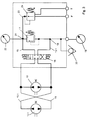
- FIG. 3 shows a control of the braking devices 10, 10.1, the braking devices 10, 10.1 being designed as hydraulic brakes and in particular as hydrodynamic brakes.
- hydrodynamic brakes are controlled precisely and precisely, and a freely selectable braking torque for adjusting the division by compensating for play is possible.
- Another advantage of hydrodynamic brakes is that they work extremely wear-free and can be operated or controlled by computer-controlled pneumatic valves.
- the braking devices 10, 10.1 are connected to one another via connecting lines 15 and 15.1. These lead into a valve 16.
- the valve 16 is preferably designed as a three-way valve and allows a blocking position and two flow positions, a change in direction of the braking devices 10, 10.1 being included in one flow position.
- this electro-hydraulic valve can be actuated manually in both directions, but also via electromagnets with return springs. It switches the braking devices 10, 101 off or on.
- the connecting lines 15 and 15.1 lead from the valve 16 to a pressure limiting valve 17 which is inserted between the connecting lines 15 and 15.1.
- a braking torque of the braking device 10, 10.1 can also be precisely set and controlled by computer control via the pressure limiting valve 17.
- a pressure gauge 19 and a check valve 20 are connected to the pressure limiting valve 17 at a node 18. Hydraulic fluid can be supplied to the system via the check valve 20 and in particular its line.
- the manometer 19 shows the maximum pressure (e.g. 50 bar) that is generated by the braking devices 10, 10.1.
- a pressure gauge 22 is connected to the connecting line 15.1 at a further node 21, which indicates a low pressure (e.g. 10 bar) in the system.
- a pressure reducing valve 24 is connected to this node 21 via a line 23 for pretensioning the entire system, which valve also compensates for excess pressure in the event of thermal expansion, as is the case with hydrodynamic brakes. This is connected to a tank T. If the pressure is too low as a result of leakage or the like, hydraulic fluid can be supplied at P.
Landscapes
- Engineering & Computer Science (AREA)
- Mechanical Engineering (AREA)
- Braking Arrangements (AREA)
- Metal Rolling (AREA)
Applications Claiming Priority (2)
| Application Number | Priority Date | Filing Date | Title |
|---|---|---|---|
| DE19526071A DE19526071A1 (de) | 1995-07-18 | 1995-07-18 | Verfahren zum Walzen von Profilen in ein Werkstück |
| DE19526071 | 1995-07-18 |
Publications (3)
| Publication Number | Publication Date |
|---|---|
| EP0754511A2 true EP0754511A2 (fr) | 1997-01-22 |
| EP0754511A3 EP0754511A3 (fr) | 1997-01-29 |
| EP0754511B1 EP0754511B1 (fr) | 2001-12-12 |
Family
ID=7767073
Family Applications (1)
| Application Number | Title | Priority Date | Filing Date |
|---|---|---|---|
| EP95111557A Expired - Lifetime EP0754511B1 (fr) | 1995-07-18 | 1995-07-22 | Procédé pour laminer des profilés dans une pièce |
Country Status (3)
| Country | Link |
|---|---|
| EP (1) | EP0754511B1 (fr) |
| DE (2) | DE19526071A1 (fr) |
| ES (1) | ES2167387T3 (fr) |
Cited By (3)
| Publication number | Priority date | Publication date | Assignee | Title |
|---|---|---|---|---|
| DE19718257A1 (de) * | 1997-04-30 | 1998-11-12 | Bad Dueben Profilwalzmaschinen | Profilwalzmaschine zum Walzen eines rotationssymmetrischen Werkstücks mit einem präzisen Außenprofil |
| EP1208927A3 (fr) * | 2000-11-24 | 2003-05-02 | Mando Corporation | Machine de laminage pour la fabrication simultanée de dents de types différents |
| WO2012007543A1 (fr) * | 2010-07-14 | 2012-01-19 | Hilti Aktiengesellschaft | Procédé de fabrication d'un demi-produit et demi-produit |
Families Citing this family (3)
| Publication number | Priority date | Publication date | Assignee | Title |
|---|---|---|---|---|
| DE20312485U1 (de) | 2003-03-04 | 2003-10-16 | Langenstein & Schemann Gmbh, 96450 Coburg | Walzmaschine zum Umformen eines Werkstücks |
| DE10316249B4 (de) * | 2003-03-04 | 2010-04-15 | Langenstein & Schemann Gmbh | Verfahren zum Umformen eines Werkstückes und Walzmaschine |
| DE10339733A1 (de) * | 2003-08-28 | 2004-11-25 | Siemens Ag | Antrieb zum rotatorischen Betrieb einer Walze |
Family Cites Families (5)
| Publication number | Priority date | Publication date | Assignee | Title |
|---|---|---|---|---|
| LU30467A1 (fr) * | ||||
| JPS5916853B2 (ja) * | 1978-11-21 | 1984-04-18 | 株式会社網野鉄工所 | プレス機械におけるロ−ルフイ−ド式材料自動供給装置 |
| JPS6277108A (ja) * | 1985-09-30 | 1987-04-09 | Nippon Kokan Kk <Nkk> | 圧延機のシヨツクトルク軽減装置 |
| FR2676668B1 (fr) * | 1991-05-23 | 1994-07-01 | Escofier Tech Sa | Dispositif et procede permettant le formage a froid de cannelures sur la paroi d'une piece de revolution. |
| JP2810988B2 (ja) * | 1991-08-20 | 1998-10-15 | 川崎製鉄株式会社 | リブ位相ずれ防止方法および装置 |
-
1995
- 1995-07-18 DE DE19526071A patent/DE19526071A1/de not_active Withdrawn
- 1995-07-22 ES ES95111557T patent/ES2167387T3/es not_active Expired - Lifetime
- 1995-07-22 EP EP95111557A patent/EP0754511B1/fr not_active Expired - Lifetime
- 1995-07-22 DE DE59509943T patent/DE59509943D1/de not_active Expired - Lifetime
Cited By (6)
| Publication number | Priority date | Publication date | Assignee | Title |
|---|---|---|---|---|
| DE19718257A1 (de) * | 1997-04-30 | 1998-11-12 | Bad Dueben Profilwalzmaschinen | Profilwalzmaschine zum Walzen eines rotationssymmetrischen Werkstücks mit einem präzisen Außenprofil |
| DE19718257C2 (de) * | 1997-04-30 | 2001-06-07 | Bad Dueben Profilwalzmaschinen | Profilwalzmaschine zum Walzen eines rotationssymmetrischen Werkstücks mit einem präzisen Außenprofil |
| EP1208927A3 (fr) * | 2000-11-24 | 2003-05-02 | Mando Corporation | Machine de laminage pour la fabrication simultanée de dents de types différents |
| WO2012007543A1 (fr) * | 2010-07-14 | 2012-01-19 | Hilti Aktiengesellschaft | Procédé de fabrication d'un demi-produit et demi-produit |
| US9718115B2 (en) | 2010-07-14 | 2017-08-01 | Hilti Aktiengesellschaft | Production method for a semi-finished product and semi-finished product |
| US9782820B2 (en) | 2010-07-14 | 2017-10-10 | Hilti Aktiengesellschaft | Production method for a semi-finished product |
Also Published As
| Publication number | Publication date |
|---|---|
| DE59509943D1 (de) | 2002-01-24 |
| ES2167387T3 (es) | 2002-05-16 |
| DE19526071A1 (de) | 1997-01-23 |
| EP0754511B1 (fr) | 2001-12-12 |
| EP0754511A3 (fr) | 1997-01-29 |
Similar Documents
| Publication | Publication Date | Title |
|---|---|---|
| DE69830133T2 (de) | Verfahren zur Herstellung eines Getrieberades | |
| DE69907365T2 (de) | Gewindeschneideinheit | |
| DE69816145T2 (de) | Verfahren und Vorrichtung zur Herstellung einer Zahnstange | |
| EP1286794B2 (fr) | Machine de laminage a froid | |
| EP0017660A1 (fr) | Presse hydraulique | |
| DE3718884C2 (de) | Vorrichtung zum Herstellen von schrägverzahnten Werkstücken aus Metall, vorzugsweise Stahl | |
| DE102007039959B4 (de) | Verfahren zum Kaltwalzen von längsgerichteten Verzahnungen und Profilen bei langen wellenförmigen Werkstücken und Profilwalzmaschine hierzu | |
| EP0754511B1 (fr) | Procédé pour laminer des profilés dans une pièce | |
| DE69211654T2 (de) | Vorrichtung und verfahren zum kaltformen von nuten in die wandung eines rotationskörpers | |
| DE2401591C3 (de) | Rohrvorschubeinrichtung zum Einbringen eines auszuwalzenden Rohres in die Formänderungszone eines Kaltpilgerwalzwerkes | |
| EP0761338B1 (fr) | Procédé et dispositif pour la fabrication d'articles profilés | |
| DE3119407A1 (de) | Anstellvorrichtung zum einstellen des walzenabstandes in walzgeruesten | |
| EP3414030B1 (fr) | Dispositif de galetage de pièces munies d'une denture et procédé afférent | |
| DE102004010444A1 (de) | Verfahren zur Herstellung einer Innenkontur mit einem auf die Innenwandung eines topfförmigen oder ringförmigen rotationssymmetrischen Werkstücks einwirkenden Innendorn | |
| DE1961606A1 (de) | Verfahren und Vorrichtung zum Formen von Zahnradzaehnen | |
| DE3611399C2 (de) | Übertragungseinrichtung für den Antrieb einer Radkörper-Formgebungseinrichtung | |
| EP1894708A1 (fr) | Dispositif d'entrainement pour une presse, une presse de poinçonnage ou un dispositif de formage | |
| DE19954210A1 (de) | Rundknetmaschine | |
| DE19718257C2 (de) | Profilwalzmaschine zum Walzen eines rotationssymmetrischen Werkstücks mit einem präzisen Außenprofil | |
| DE4124772C2 (fr) | ||
| DE10244483B4 (de) | Profilwalzmaschine mit Kraftrahmen zum Walzen mit außenverzahnten Rundwalzwerkzeugen | |
| DE112009001413B4 (de) | Walzmaschine zum Umformen von metallischen und/oder eisenhaltigen Werkstücken mit verstellbaren Walzen | |
| DE19710730B4 (de) | Walzverfahren und Zweiwalzen-Profilwalzmaschine zum Herstellen von Steigungsprofilen mit ungerader Gangzahl auf rotationssymmetrische Werkstücke | |
| DE2503284C3 (de) | Walzendrehbank | |
| AT520360B1 (de) | Vorrichtung zum Klemmen eines Werkstücks |
Legal Events
| Date | Code | Title | Description |
|---|---|---|---|
| PUAI | Public reference made under article 153(3) epc to a published international application that has entered the european phase |
Free format text: ORIGINAL CODE: 0009012 |
|
| PUAL | Search report despatched |
Free format text: ORIGINAL CODE: 0009013 |
|
| AK | Designated contracting states |
Kind code of ref document: A2 Designated state(s): CH DE ES FR GB IT LI |
|
| AK | Designated contracting states |
Kind code of ref document: A3 Designated state(s): CH DE ES FR IT LI |
|
| 17P | Request for examination filed |
Effective date: 19970707 |
|
| 17Q | First examination report despatched |
Effective date: 20000201 |
|
| GRAG | Despatch of communication of intention to grant |
Free format text: ORIGINAL CODE: EPIDOS AGRA |
|
| GRAG | Despatch of communication of intention to grant |
Free format text: ORIGINAL CODE: EPIDOS AGRA |
|
| GRAH | Despatch of communication of intention to grant a patent |
Free format text: ORIGINAL CODE: EPIDOS IGRA |
|
| GRAH | Despatch of communication of intention to grant a patent |
Free format text: ORIGINAL CODE: EPIDOS IGRA |
|
| RBV | Designated contracting states (corrected) |
Designated state(s): CH DE ES FR GB IT LI |
|
| GRAA | (expected) grant |
Free format text: ORIGINAL CODE: 0009210 |
|
| AK | Designated contracting states |
Kind code of ref document: B1 Designated state(s): CH DE ES FR GB IT LI |
|
| PG25 | Lapsed in a contracting state [announced via postgrant information from national office to epo] |
Ref country code: GB Free format text: LAPSE BECAUSE OF FAILURE TO SUBMIT A TRANSLATION OF THE DESCRIPTION OR TO PAY THE FEE WITHIN THE PRESCRIBED TIME-LIMIT Effective date: 20011212 |
|
| REG | Reference to a national code |
Ref country code: CH Ref legal event code: EP |
|
| REG | Reference to a national code |
Ref country code: CH Ref legal event code: NV Representative=s name: FREI PATENTANWALTSBUERO |
|
| REG | Reference to a national code |
Ref country code: GB Ref legal event code: IF02 |
|
| REF | Corresponds to: |
Ref document number: 59509943 Country of ref document: DE Date of ref document: 20020124 |
|
| REG | Reference to a national code |
Ref country code: ES Ref legal event code: FG2A Ref document number: 2167387 Country of ref document: ES Kind code of ref document: T3 |
|
| ET | Fr: translation filed | ||
| GBV | Gb: ep patent (uk) treated as always having been void in accordance with gb section 77(7)/1977 [no translation filed] |
Effective date: 20011212 |
|
| PLBE | No opposition filed within time limit |
Free format text: ORIGINAL CODE: 0009261 |
|
| STAA | Information on the status of an ep patent application or granted ep patent |
Free format text: STATUS: NO OPPOSITION FILED WITHIN TIME LIMIT |
|
| 26N | No opposition filed | ||
| PGFP | Annual fee paid to national office [announced via postgrant information from national office to epo] |
Ref country code: CH Payment date: 20110725 Year of fee payment: 17 |
|
| PGFP | Annual fee paid to national office [announced via postgrant information from national office to epo] |
Ref country code: ES Payment date: 20110726 Year of fee payment: 17 |
|
| REG | Reference to a national code |
Ref country code: CH Ref legal event code: PL |
|
| PG25 | Lapsed in a contracting state [announced via postgrant information from national office to epo] |
Ref country code: LI Free format text: LAPSE BECAUSE OF NON-PAYMENT OF DUE FEES Effective date: 20120731 Ref country code: CH Free format text: LAPSE BECAUSE OF NON-PAYMENT OF DUE FEES Effective date: 20120731 |
|
| REG | Reference to a national code |
Ref country code: ES Ref legal event code: FD2A Effective date: 20131218 |
|
| PG25 | Lapsed in a contracting state [announced via postgrant information from national office to epo] |
Ref country code: ES Free format text: LAPSE BECAUSE OF NON-PAYMENT OF DUE FEES Effective date: 20120723 |
|
| PGFP | Annual fee paid to national office [announced via postgrant information from national office to epo] |
Ref country code: FR Payment date: 20140721 Year of fee payment: 20 |
|
| PGFP | Annual fee paid to national office [announced via postgrant information from national office to epo] |
Ref country code: IT Payment date: 20140729 Year of fee payment: 20 |
|
| PGFP | Annual fee paid to national office [announced via postgrant information from national office to epo] |
Ref country code: DE Payment date: 20140930 Year of fee payment: 20 |
|
| REG | Reference to a national code |
Ref country code: DE Ref legal event code: R082 Ref document number: 59509943 Country of ref document: DE Representative=s name: PATENTANWAELTE UND RECHTSANWALT WEISS, ARAT & , DE Ref country code: DE Ref legal event code: R082 Ref document number: 59509943 Country of ref document: DE Representative=s name: PATENTANWAELTE UND RECHTSANWALT DR. WEISS, ARA, DE |
|
| REG | Reference to a national code |
Ref country code: DE Ref legal event code: R071 Ref document number: 59509943 Country of ref document: DE |