EP1894708A1 - Dispositif d'entrainement pour une presse, une presse de poinçonnage ou un dispositif de formage - Google Patents
Dispositif d'entrainement pour une presse, une presse de poinçonnage ou un dispositif de formage Download PDFInfo
- Publication number
- EP1894708A1 EP1894708A1 EP06018309A EP06018309A EP1894708A1 EP 1894708 A1 EP1894708 A1 EP 1894708A1 EP 06018309 A EP06018309 A EP 06018309A EP 06018309 A EP06018309 A EP 06018309A EP 1894708 A1 EP1894708 A1 EP 1894708A1
- Authority
- EP
- European Patent Office
- Prior art keywords
- gear
- shaft
- drive device
- eccentric shaft
- transmission
- Prior art date
- Legal status (The legal status is an assumption and is not a legal conclusion. Google has not performed a legal analysis and makes no representation as to the accuracy of the status listed.)
- Withdrawn
Links
- 238000003825 pressing Methods 0.000 title claims description 14
- 238000004080 punching Methods 0.000 title claims description 9
- 230000005540 biological transmission Effects 0.000 claims abstract description 74
- 230000008878 coupling Effects 0.000 claims description 11
- 238000010168 coupling process Methods 0.000 claims description 11
- 238000005859 coupling reaction Methods 0.000 claims description 11
- 230000007704 transition Effects 0.000 claims description 3
- 238000009740 moulding (composite fabrication) Methods 0.000 description 28
- 238000000034 method Methods 0.000 description 11
- 230000008569 process Effects 0.000 description 11
- 230000008859 change Effects 0.000 description 7
- 238000003754 machining Methods 0.000 description 5
- 230000001360 synchronised effect Effects 0.000 description 5
- 239000012530 fluid Substances 0.000 description 4
- 230000033001 locomotion Effects 0.000 description 3
- 230000009467 reduction Effects 0.000 description 3
- 230000002349 favourable effect Effects 0.000 description 2
- 230000000737 periodic effect Effects 0.000 description 2
- 230000008901 benefit Effects 0.000 description 1
- 238000005096 rolling process Methods 0.000 description 1
Images

Classifications
-
- B—PERFORMING OPERATIONS; TRANSPORTING
- B30—PRESSES
- B30B—PRESSES IN GENERAL
- B30B1/00—Presses, using a press ram, characterised by the features of the drive therefor, pressure being transmitted directly, or through simple thrust or tension members only, to the press ram or platen
- B30B1/26—Presses, using a press ram, characterised by the features of the drive therefor, pressure being transmitted directly, or through simple thrust or tension members only, to the press ram or platen by cams, eccentrics, or cranks
- B30B1/266—Drive systems for the cam, eccentric or crank axis
Definitions
- the invention relates to a drive device for a pressing, stamping or forming machine, with a drive motor and a gearbox having two switching stages, for driving an eccentric shaft.
- the eccentric shaft of a pressing, punching or forming machines can be rotated.
- At the eccentric shaft usually at least one connecting rod is mounted, which is connected to a plunger and converts the rotational movement of the eccentric shaft in a translational movement of the plunger.
- the plunger can thereby be driven to a reciprocating motion relative to a table of the pressing, stamping or forming machines.
- At the plunger and the table cooperating tools can be held for machining a workpiece.
- the workpiece can for example be embossed, stamped or formed.
- the speed of the eccentric shaft is understood to mean the change in the rotational angle per unit of time, that is to say it is understood to be a variable that can be changed within a complete revolution of the eccentric shaft.
- the switchable planetary gear during the actual machining of the workpiece, a relatively low speed of the eccentric shaft can be achieved, whereas the remaining rotation of the eccentric shaft can be carried out at a relatively high speed in order to increase the cycle time of the pressing, punching or forming machine.
- the rotational speed of the eccentric shaft present during the machining of the workpiece is referred to below as working speed, and the rotational speed which the eccentric shaft has between two successive machining operations is referred to below as the transporting speed since the workpiece is usually transported between two successive working steps. It is therefore distinguished below between the lowest possible selected for a good workpiece machining operating speed during a step and for a shortest possible succession of steps highly selected transport speed between steps.
- a drive device in which a front-mounted gearbox can be selectively switched or bridged via switchable clutches between a flywheel and the eccentric shaft.
- This makes it possible to connect the flywheel either directly to the eccentric shaft, with a gear ratio of 1: 1 1 is achieved, or the flywheel can by interposing the gearbox with another gear ratio, such as a gear ratio of 2: 1, with the eccentric shaft be coupled.
- Object of the present invention is to develop a drive device of the type mentioned in such a way that the speed of the eccentric shaft varies over a wide speed range and the eccentric shaft can be acted upon by a large torque.
- a variable-speed drive motor can be coupled via a gearbox with the eccentric shaft.
- both the rotational speed of the drive motor and the switching stages of the gearbox can be changed during a revolution of the eccentric shaft.
- the first shift stage may have a relatively low gear ratio and the second shift stage may have a higher gear ratio.
- a low gear ratio gives the possibility to drive the eccentric shaft rotating at a relatively high speed, wherein the speed can be changed by appropriate control of the drive motor. As a result, a high number of strokes of the ram connected to the eccentric shaft can be achieved.
- the second shift stage of the gearbox may have a higher gear ratio, so that the eccentric shaft can be rotationally driven at a relatively low speed, wherein the speed can be changed by appropriate control of the drive motor.
- a high gear ratio, and associated low speed makes it possible to exert high torque on the eccentric shaft so that the ram connected to the eccentric shaft can exert a high pressing force on a tool.
- the speed of the drive motor can be varied very much, since act on the drive motor due to the high transmission ratio only small inertial forces.
- the drive motor is applied at a low transmission ratio of the gearbox with a significant inertial force, resulting from the inertia of the plunger and the attached tool and the inertia of the drive train between the eccentric shaft and the motor shaft of the drive motor.
- High inertial force affects the ability of the drive motor to change the speed. It is therefore advantageous if the drive motor is acted upon only with a relatively low inertial force, the required high transmission ratio is provided by the transmission.
- the gearbox is coupled on the output side with another transmission.
- the further transmission is thus arranged in the drive train between the gearbox and the eccentric shaft and allows an additional reduction of the speed of the drive motor and thus a higher torque loading of the eccentric shaft.
- the further transmission has a fixed transmission ratio, for example a transmission ratio of 4: 1.
- the further transmission can be configured, for example, as a planetary gear.
- the drive motor of the drive device is preferably configured as a servomotor or as a torque motor.
- Servo motors are characterized by the fact that they are angularly accurate and controllable in their speed.
- Torquemotors have the advantage that they provide a high torque at a relatively low speed. Frequently, the torque delivered by the torque motor is at least a factor of 2 greater than that of corresponding servomotors with comparable power.
- the speed of a torque motor is compared to a servomotor with comparable power in many cases lower by a factor of 2 to 10. For both types of engine, the speed can be varied electronically.
- the drive device may have a corresponding electrical control unit.
- the rotary connection between the drive motor and the eccentric shaft by means of the gearbox is selectively switched on and off.
- This makes it possible to decouple the drive motor completely from the eccentric shaft, so that it can be locked in rotation by means of a brake.
- a rotationally fixed locking of the eccentric shaft is provided, for example, in a tool change of the pressing, punching or forming machines.
- the rotary joint can be switched on and off by means of the gearbox without additional components must be used.
- the transmission thus has a state in which it completely interrupts the drive train between the drive motor and the eccentric shaft.
- This also gives the possibility to change the speed of the drive motor at a constant speed of the eccentric shaft.
- the rotary connection between the eccentric shaft and the drive motor optionally switched on and off and the switching stages of the gearbox can be changed.
- the rotational speed of the drive motor can be changed during the transition of the shift transmission between two shift stages, that is, for example, from a first to a second shift stage.
- the transmission is in a first stage, the eccentric shaft rotates at a speed, taking into account the transmission ratio of this Switching stage corresponds to the speed of the drive motor.
- the speed of the drive motor can first be adapted to the synchronous speed of the second switching stage, that is, the speed of the drive motor can be varied such that it takes into account the transmission ratio of the second switching stage the speed of the eccentric shaft corresponds.
- the manual transmission can first be operated in a first switching stage, which is characterized by a low gear ratio, so that the eccentric shaft can be rotated at high speed.
- the switching stage can be changed slip-free, so that the step can be performed at a high gear ratio of the gearbox.
- the high transmission ratio makes it possible to decelerate the eccentric shaft by means of the drive motor until the desired reduced forming speed is reached.
- the forming process can be carried out at reduced forming speed with full utilization of the engine torque. After the forming process, that is, after completion of the step, can be changed again without slipping in the original switching stage to rotate with the highest possible transport speed, the eccentric shaft until the next step.
- the transmission has in a preferred embodiment of the invention, a first, connected to the drive motor gear shaft and a second, connectable to the eccentric shaft gear shaft and a first gear stage with a first gear ratio and a second gear stage with a second gear ratio, wherein the gear shafts are selectively coupled to each other via the first or the second gear stage and wherein between the gear stages and the first and / or the second gear shaft switchable clutches are arranged.
- Under a gear stage here are mutually operatively connected gear parts understood that provide a coupling of the first gear shaft with the second gear shaft while providing a predetermined gear ratio.
- a switchable clutch is arranged between the first transmission shaft and the first gear stage and between the first gear shaft and the second gear stage.
- the shiftable clutches each allow a releasable rotational connection of the first transmission shaft with the first and the second gear stage.
- the second transmission shaft may be rotatably connected to both the first and the second gear stage.
- the first transmission shaft can be completely decoupled from the second transmission shaft by means of the switchable clutches. This makes it possible to change the speed of the coupled with the motor shaft first gear shaft regardless of the speed of the second gear shaft.
- the drive train between the drive motor and the eccentric shaft can thereby be interrupted in a structurally simple manner.
- the switchable couplings are preferably hydraulically actuated. This makes it possible to control the switchable clutches by applying pressurized hydraulic fluid.
- a further clutch can be used.
- the first transmission shaft is rotatably connected to the motor shaft of the drive motor.
- the second transmission shaft can be coupled to the eccentric shaft via a transmission with a fixed transmission ratio. This allows a reduction of the speed of the second transmission shaft.
- the additional transmission may for example have a transmission ratio of 4: 1.
- the second transmission shaft via a planetary gear with the eccentric shaft can be coupled.
- a high torque can be provided by the use of the planetary gear of the eccentric shaft.
- the second transmission shaft is rotatably connected to the sun gear of the planetary gear.
- the eccentric shaft is conveniently connectable to the planetary carrier of the planetary gear.
- the ring gear of the planetary gear is rotatably connected in a preferred embodiment with the housing of the gearbox.
- the first and second gear stage are each designed as a gear pair with a first and a second gear, wherein the two gears are coupled to each other via a rotary connection and wherein one of the two gears rotatably with a gear shaft and the other Gear is connected via a switchable coupling with the other gear shaft.
- This allows a structurally particularly simple embodiment of the gearbox.
- the switchable clutches alternatively, the first gear pair or the second gear pair can be used to couple the two gear shafts.
- the two Geretedcrue are characterized by different gear ratios. In particular, it can be provided that the transmission ratio of the first Geretedcrues is twice as large as the transmission ratio of the second Geretedcrues. For example, ratios of 2: 1 and 4: 1 can be used.
- the gear wheels of the two pairs of gear wheels are designed as intermeshing toothed wheels, in particular in the form of external toothed spur gears.
- the two transmission shafts are preferably aligned parallel to one another.
- the drive device has a control unit which is connected to the drive motor.
- additional measuring elements in particular sensors for determining the rotational speed of the eccentric shaft and the motor shaft of the drive motor are used, wherein the measuring elements are connected to the control unit.
- the speeds of the eccentric shaft and the motor shaft can be determined. This gives the possibility in particular of adapting the rotational speed of the drive motor during the transition of the gearbox from a first to a second gearshift stage by a corresponding control of the drive motor to the rotational speed of the eccentric shaft, so that the switching operation can be carried out slip-free and wear-free.
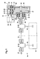
- a drive device 10 according to the invention is shown schematically, which is connected to an eccentric shaft 12 of a press, punching or forming machine 14 shown only in part.
- the latter has a plunger 16 which is connected via two connecting rods 18, 19 with the eccentric shaft 12.
- the eccentric shaft 12 is rotatable by means of rolling or sliding bearings 20 on a frame, not shown in the drawing of the known Pressing, stamping or forming machines 14 stored. With the aid of a sensor 22, the speed of the eccentric shaft 12 can be detected.
- the drive device 10 comprises a drive motor, which is designed as a servomotor 24 in the illustrated embodiment. Alternatively, a torque motor can be used.
- the servo motor 24 is controlled by a control unit 25 which is connected to the sensor 22 via a signal line, not shown in the drawing.
- the drive device 10 also has a gearbox 28 with a housing 29 on which a first gear shaft 31 and a parallel to the first gear shaft 31 aligned second gear shaft 32 are rotatably mounted.
- the first transmission shaft 31 is non-rotatably connected via a rigid coupling 34 to the motor shaft 36 of the servomotor 24.
- a first pinion 38 and a second pinion 39 are freely rotatably mounted, and each pinion 38, 39 is a switchable coupling 41 and 42 assigned, which is hydraulically controlled and a rotationally fixed connection of the respective pinion 38 and 39, respectively with the first transmission shaft 31 allows.
- the second pinion 39 is additionally associated with a spring-loaded, hydraulically releasable brake 44, with the aid of which the second pinion 39 can be rotatably fixed to the housing 29 of the gearbox 28.
- the brake 44 By means of the brake 44, the eccentric shaft 12 and the plunger 16 can be braked.
- the first pinion 38 meshes with a first gear 46, which is non-rotatably mounted on the second gear shaft 32, and the second pinion 39 meshes with a second gear 47, which also rotatably seated on the second gear shaft 32.
- the second gear shaft 32 protrudes with its free end in the direction of the eccentric shaft 12 out of the housing 29 of the gearbox 28 and carries at its protruding end rotatably the sun gear 49 of a planetary gear 50.
- the sun gear meshes with a plurality of planetary gears 52 52, which rotatably on a connected to the eccentric shaft 12 planet carrier 54 are freely rotatably and with the internal teeth of a rotatably connected to the housing 29 ring gear 56 are engaged.
- the first pinion 38 forms in combination with the first gear 46, a first gear stage of the gearbox 28 with a transmission ratio of, for example, 2: 1.
- the second pinion 39 forms in combination with the second gear 47, a second gear stage of the gearbox 28 with a double In a first shift stage of the gearbox 28, the first gear stage is effective by the first switchable clutch 41 is acted upon by pressurized hydraulic fluid and thereby a rotationally fixed connection between the first sprocket 38 and the first gear shaft 31 while the second switchable clutch 42 remains unactuated, so that the second sprocket 39 is freely rotatable relative to the first gear shaft 31.
- the second gear stage is effective by the second switchable clutch 42 is acted upon by pressurized hydraulic fluid, while the first switchable clutch 41 is unconfirmed.
- the second pinion gear 39 is thus rotatably connected to the first gear shaft 31 in the second shift stage, whereas the first pinion gear 38 is freely rotatable relative to the first gear shaft 31.
- the drive device 10 has several operating modes.
- a first mode of operation the servomotor 24 is operated at a constant speed and is coupled to the eccentric shaft 12 via the first gear stage, that is to say via the first pinion 38 and the first gear 46, and via the planetary gear 50.
- This allows a high speed of the eccentric shaft 12 and thus a high stroke rate of the plunger 16, since the first gear stage causes a relatively low reduction of the engine speed.
- the brake 44 is released hydraulically and it becomes the first switchable coupling 41 hydraulically actuated. This will over the first gear shaft 31, the first clutch 41, the first pinion 38 and the first gear 46 and then achieved via the planetary gear 50, a frictional connection between the servo motor 24 and the eccentric shaft 12.
- the servo motor 24 is also connected via the first gear stage and the planetary gear 50 with the eccentric shaft, but the rotational speed of the servomotor 24 is changed periodically, so that the eccentric shaft 12 during a working step of the plunger 16 is a relatively low speed whereas, between two consecutive operations, the eccentric shaft 12 is driven at high speed.
- a third mode of the drive device 10 is characterized by a lower speed of the eccentric shaft 12 by the servomotor 24 is operated at a constant speed and the second gear stage, that is, via the second pinion 39 and the second gear 47, and the planetary gear 50 with the eccentric shaft 12 is connected.
- the second switchable clutch 42 is hydraulically actuated, so that via the first gear shaft 31, the second pinion 39, the second gear 47, the second transmission shaft 32 and the planetary gear 50, a frictional connection between the servo motor 24 and the eccentric shaft 12 is achieved. Due to the twice the transmission ratio of the second gear stage (second pinion 39 and second gear 47) rotates the eccentric shaft 12 compared to the first mode with half the speed, but it is provided twice as large torque.
- a fourth mode of operation of the drive device 10 is characterized in that the frictional connection between the servo motor 24 and the eccentric shaft 12 is also achieved via the second gear stage (second pinion 39 and second gear 47), however, the servomotor 24 is operated at periodically changed speed , This makes it possible to rotate the eccentric shaft 12 during a work step at a very low speed and between two successive steps with significantly increased speed.
- the relatively high transmission ratio of the second gear stage has the consequence that acts on the servo motor 24, only a relatively small inertial force. As a result, the engine speed can be greatly reduced, and thus a forming process with particularly low speed of the plunger 16 can be performed.
- the servo motor 24 is operated at a constant speed, but the manual transmission 28 periodically switches between the first and the second shift position back and forth.
- the brake 44 is hydraulically released when starting the pressing, punching or forming machine 14 in the fifth mode of the drive device 10 and it is the first switchable in a first step Clutch 41 actuated.
- the first shiftable clutch 41 is released and the second shiftable clutch 42 is actuated.
- the adhesion thus changes from the first gear stage to the second gear stage (second pinion 39 and second gear 47).
- the switching process is completed at the latest at a rotational angle of about 140 ° of the eccentric shaft 12, because the forming process is usually carried out at about 150 °. If deviating angles of rotation are required for the forming process, then the switching operation can be adapted via the control unit 25 to the respective requirements.
- the speed of the eccentric shaft 12 and thus the speed of the plunger 16 is reduced by the switching operation of the gearbox 28 according to the gear ratios of the two gear stages.
- the forming process that is, the operation of the pressing, stamping or forming machine 14, can be performed with reduced forming speed with full utilization of the torque of the servomotor 24.
- the second shiftable clutch 42 is released and the first shiftable clutch 41 is actuated.
- the frictional connection thus changes from the second gear stage to the first gear stage.
- the eccentric shaft 12 is thus accelerated again, since it is now driven again via the first gear stage. This state is maintained until the rotational speed of the eccentric shaft 12 of approximately 100 ° is reached again when the manual transmission 28 is switched again.
- a sixth mode of operation of the drive device 10 is characterized in that both periodic switching operations of the gearbox 28 and periodic changes in the rotational speed of the servomotor 24 are performed.
- the servomotor 24 is first coupled via the first gear stage and the planetary gear 50 with the eccentric shaft 12. At a rotation angle of the eccentric shaft 12 of approximately 100 °, the first shiftable clutch 41 is released and also the second switchable coupling 42 initially remains in its released state.
- the servo motor 24 is thus connected via the rigid coupling 34 only with the first transmission shaft 31 and the rotatably connected to the first transmission shaft 31 inner parts of the switchable clutches 41 and 42 and the brake 44.
- the servomotor 24 can be greatly accelerated within a very short time until the rotational speed of the first transmission shaft 31 corresponds to the second speed synchronous rotational speed, that is, until the rotational speed of the first transmission shaft 31 in consideration of the gear ratio the second gear stage of the rotational speed of the second gear shaft 32 corresponds.
- the corresponding rotational speeds are detected by the servomotor 24 by means of an internal measuring element of the servo motor 24 and by the second gear shaft 32 by means of the sensor 22 arranged on the eccentric shaft 12, taking into account the transmission ratio of the planetary gear 50.
- the second shiftable clutch 42 is released, so that the servo motor 24 via the rigid clutch 34 only with the first transmission shaft 31 and the rotationally fixed to the first transmission shaft 31 connected inside parts of the switchable clutches 41 and 42 and the brake 44 is connected.
- the servomotor 24 can decelerate until the rotational speed of the first transmission shaft 31 corresponds to the synchronous rotational speed of the first gear stage, that is, until the rotational speed of the first transmission shaft 31 takes into account the gear ratio of the first gear stage of the rotational speed the second transmission shaft 32 corresponds.
- the first switchable clutch 41 is hydraulically actuated, so that the manual transmission 28 goes back into the first switching state and the adhesion occurs from the engine 24 via the first gear stage and the planetary gear 50 to the eccentric shaft 12.
- the eccentric shaft 12 is now accelerated to reach in the shortest possible time again a rotation angle of about 100 °, so that then a renewed switching cycle can be performed.
- the drive device 10 allows the eccentric shaft 12 to be driven at different speeds while providing high torque.
- a different speed of the eccentric shaft 12 can be achieved due to the different gear ratios, and in addition, the speed of the eccentric shaft 12 can be varied by the servo motor 24. It can be achieved a synchronization of the switching operation of the gearbox 28, so that switching operations can be performed without slip and wear.
Landscapes
- Engineering & Computer Science (AREA)
- Mechanical Engineering (AREA)
- Structure Of Transmissions (AREA)
Priority Applications (1)
| Application Number | Priority Date | Filing Date | Title |
|---|---|---|---|
| EP06018309A EP1894708A1 (fr) | 2006-09-01 | 2006-09-01 | Dispositif d'entrainement pour une presse, une presse de poinçonnage ou un dispositif de formage |
Applications Claiming Priority (1)
| Application Number | Priority Date | Filing Date | Title |
|---|---|---|---|
| EP06018309A EP1894708A1 (fr) | 2006-09-01 | 2006-09-01 | Dispositif d'entrainement pour une presse, une presse de poinçonnage ou un dispositif de formage |
Publications (1)
| Publication Number | Publication Date |
|---|---|
| EP1894708A1 true EP1894708A1 (fr) | 2008-03-05 |
Family
ID=38009745
Family Applications (1)
| Application Number | Title | Priority Date | Filing Date |
|---|---|---|---|
| EP06018309A Withdrawn EP1894708A1 (fr) | 2006-09-01 | 2006-09-01 | Dispositif d'entrainement pour une presse, une presse de poinçonnage ou un dispositif de formage |
Country Status (1)
| Country | Link |
|---|---|
| EP (1) | EP1894708A1 (fr) |
Cited By (7)
| Publication number | Priority date | Publication date | Assignee | Title |
|---|---|---|---|---|
| DE102008057019A1 (de) * | 2008-11-12 | 2010-05-20 | Reinhard Schmid | Umformwerkzeug zur Bearbeitung von Werkstücken |
| ITPG20100030A1 (it) * | 2010-05-05 | 2011-11-06 | Mario Battistelli | Sistema elettromeccanico assiale e a leveraggio per la produzione di oggetti termoformati, con basso consumo di materia prima, alta flessibilita' sul prodotto da termoformare e sulle corse di lavoro. |
| US8727931B2 (en) | 2010-04-09 | 2014-05-20 | Bruderer Ag | Gear train unit and arrangement for a stamping press |
| WO2017035671A1 (fr) * | 2015-09-02 | 2017-03-09 | Bruderer Ag | Presse d'emboutissage et/ou de formage |
| US11541618B1 (en) | 2021-09-21 | 2023-01-03 | PDInnovative LLC | Linear-actuated press machine having multiple motors and clutch system for multi-speed drive functionality |
| US11752720B2 (en) | 2021-09-08 | 2023-09-12 | PDInnovative LLC | Press machine with modular linear actuator system |
| US11819906B2 (en) | 2021-09-21 | 2023-11-21 | PDInnovative LLC | Linear-actuated press machine having multiple motors and clutch system for multi-speed drive functionality |
Citations (8)
| Publication number | Priority date | Publication date | Assignee | Title |
|---|---|---|---|---|
| GB1215841A (en) | 1967-10-02 | 1970-12-16 | Verson Allsteel Press Co | Plural speed mechanical transmission systems |
| DE1627971A1 (de) | 1967-12-02 | 1971-07-29 | Schuler Gmbh L | Schleichgangantrieb fuer Pressen |
| DD125530A1 (fr) * | 1976-05-10 | 1977-04-27 | ||
| JPS5970497A (ja) * | 1982-10-14 | 1984-04-20 | Aida Eng Ltd | プレス変速駆動装置 |
| DE29906519U1 (de) | 1999-04-13 | 1999-08-12 | Desch Antriebstechnik GmbH & Co KG, 59759 Arnsberg | Antrieb für eine mechanische Presse |
| JP2001347400A (ja) * | 2000-06-08 | 2001-12-18 | Murata Mach Ltd | プレス装置 |
| DE10111346C2 (de) | 2001-03-08 | 2003-03-20 | Desch Antriebstechnik Gmbh & Co Kg | Antriebseinrichtung, insbesondere für eine mechanische Presse oder Stanze |
| JP2004243377A (ja) * | 2003-02-14 | 2004-09-02 | Fuji-Steel Industry Co Ltd | プレス機 |
-
2006
- 2006-09-01 EP EP06018309A patent/EP1894708A1/fr not_active Withdrawn
Patent Citations (8)
| Publication number | Priority date | Publication date | Assignee | Title |
|---|---|---|---|---|
| GB1215841A (en) | 1967-10-02 | 1970-12-16 | Verson Allsteel Press Co | Plural speed mechanical transmission systems |
| DE1627971A1 (de) | 1967-12-02 | 1971-07-29 | Schuler Gmbh L | Schleichgangantrieb fuer Pressen |
| DD125530A1 (fr) * | 1976-05-10 | 1977-04-27 | ||
| JPS5970497A (ja) * | 1982-10-14 | 1984-04-20 | Aida Eng Ltd | プレス変速駆動装置 |
| DE29906519U1 (de) | 1999-04-13 | 1999-08-12 | Desch Antriebstechnik GmbH & Co KG, 59759 Arnsberg | Antrieb für eine mechanische Presse |
| JP2001347400A (ja) * | 2000-06-08 | 2001-12-18 | Murata Mach Ltd | プレス装置 |
| DE10111346C2 (de) | 2001-03-08 | 2003-03-20 | Desch Antriebstechnik Gmbh & Co Kg | Antriebseinrichtung, insbesondere für eine mechanische Presse oder Stanze |
| JP2004243377A (ja) * | 2003-02-14 | 2004-09-02 | Fuji-Steel Industry Co Ltd | プレス機 |
Cited By (12)
| Publication number | Priority date | Publication date | Assignee | Title |
|---|---|---|---|---|
| DE102008057019A1 (de) * | 2008-11-12 | 2010-05-20 | Reinhard Schmid | Umformwerkzeug zur Bearbeitung von Werkstücken |
| US8727931B2 (en) | 2010-04-09 | 2014-05-20 | Bruderer Ag | Gear train unit and arrangement for a stamping press |
| ITPG20100030A1 (it) * | 2010-05-05 | 2011-11-06 | Mario Battistelli | Sistema elettromeccanico assiale e a leveraggio per la produzione di oggetti termoformati, con basso consumo di materia prima, alta flessibilita' sul prodotto da termoformare e sulle corse di lavoro. |
| WO2017035671A1 (fr) * | 2015-09-02 | 2017-03-09 | Bruderer Ag | Presse d'emboutissage et/ou de formage |
| US11752720B2 (en) | 2021-09-08 | 2023-09-12 | PDInnovative LLC | Press machine with modular linear actuator system |
| US12214567B2 (en) | 2021-09-08 | 2025-02-04 | PDInnovative LLC | Press machine having planetary gear system for multi-speed drive functionality |
| US12570065B2 (en) | 2021-09-08 | 2026-03-10 | PDInnovative LLC | Press machine with modular linear actuator system |
| US11541618B1 (en) | 2021-09-21 | 2023-01-03 | PDInnovative LLC | Linear-actuated press machine having multiple motors and clutch system for multi-speed drive functionality |
| US11819906B2 (en) | 2021-09-21 | 2023-11-21 | PDInnovative LLC | Linear-actuated press machine having multiple motors and clutch system for multi-speed drive functionality |
| US11904564B2 (en) | 2021-09-21 | 2024-02-20 | PDInnovative LLC | Linear-actuated press machine having multiple motors and clutch system for multi-speed drive functionality |
| US11919267B2 (en) | 2021-09-21 | 2024-03-05 | PDInnovative LLC | Linear-actuated press machine having telescopic drive configuration for multi-speed drive functionality |
| US12214414B2 (en) | 2021-09-21 | 2025-02-04 | PDInnovative LLC | Linear-actuated press machine having multiple motors and clutch system for multi-speed drive functionality |
Similar Documents
| Publication | Publication Date | Title |
|---|---|---|
| DE69301361T2 (de) | Antriebseinrichtung für eine mechanische Presse | |
| DE2342771C2 (de) | Wechselgetriebe mit Bereichsumschaltung | |
| EP1610038B1 (fr) | Transmission à double embrayage et methode de controle d'une transmission à double embrayage | |
| EP0786297A1 (fr) | Mécanisme d'entraînement pour une machine de formage | |
| DE2406076C2 (de) | Zahnradgetriebe mit Spielausgleich | |
| EP0897493A1 (fr) | Procede pour commander les embrayages d'une transmission a division de puissance mecano-hydrostatique | |
| EP3126701A1 (fr) | Procédé de commande d'un système d'actionnement d'un embrayage, système d'actionnement, et système d'entraînement muni dudit système d'actionnement | |
| EP2375102A1 (fr) | Unité d'engrenage et agencement pour presse de découpage | |
| EP2008800A1 (fr) | Dispositif d'actionnement pour un automate de presse, de découpe ou de déformage | |
| EP3065945B1 (fr) | Unité de transmission et ensemble pour une presse à découper | |
| EP3593918A1 (fr) | Outil à rouleaux pour une machine-outil, système d'outil à rouleaux et procédé de formage linéaire d'une tôle | |
| DE202006013440U1 (de) | Antriebseinrichtung für einen Press-, Stanz- oder Umformautomaten | |
| EP0543196B1 (fr) | Dispositif d'entraînement pour des machines à engommer des couvercles | |
| DE3119407A1 (de) | Anstellvorrichtung zum einstellen des walzenabstandes in walzgeruesten | |
| EP1460305A1 (fr) | Transmission | |
| DE202007009064U1 (de) | Antriebseinrichtung für einen Press-, Stanz- oder Umformautomaten | |
| DE19959394C2 (de) | Antriebsvorrichtung für eine Umformmaschine | |
| DE19962630B4 (de) | Antriebsvorrichtung für eine Umformmaschine | |
| EP2529922B1 (fr) | Dispositif d'actionnement pour un automate de presse, de découpe ou de déformage | |
| AT509089B1 (de) | Hubpresse oder hubstanze mit schaltbarem planetengetriebe | |
| WO2008141607A1 (fr) | Entrainement hybride pour une presse de transfert à plusieurs coulisseaux ou un train de presse | |
| DE19718257C2 (de) | Profilwalzmaschine zum Walzen eines rotationssymmetrischen Werkstücks mit einem präzisen Außenprofil | |
| DE1500354C3 (fr) | ||
| DE202011101349U1 (de) | Antriebseinrichtung für einen Press-, Stanz- oder Umformautomaten | |
| DE2410163C2 (de) | Zahnräderwechselgetriebe in Gruppenbauweise, insbesondere für land- und/oder bauwirtschaftlich nutzbare Kraftfahrzeuge |
Legal Events
| Date | Code | Title | Description |
|---|---|---|---|
| PUAI | Public reference made under article 153(3) epc to a published international application that has entered the european phase |
Free format text: ORIGINAL CODE: 0009012 |
|
| AK | Designated contracting states |
Kind code of ref document: A1 Designated state(s): AT BE BG CH CY CZ DE DK EE ES FI FR GB GR HU IE IS IT LI LT LU LV MC NL PL PT RO SE SI SK TR |
|
| AX | Request for extension of the european patent |
Extension state: AL BA HR MK YU |
|
| 17P | Request for examination filed |
Effective date: 20080827 |
|
| AKX | Designation fees paid |
Designated state(s): AT BE BG CH CY CZ DE DK EE ES FI FR GB GR HU IE IS IT LI LT LU LV MC NL PL PT RO SE SI SK TR |
|
| 17Q | First examination report despatched |
Effective date: 20081106 |
|
| STAA | Information on the status of an ep patent application or granted ep patent |
Free format text: STATUS: THE APPLICATION HAS BEEN WITHDRAWN |
|
| 18W | Application withdrawn |
Effective date: 20150706 |