EP0754906A2 - Dispositif de fixation - Google Patents
Dispositif de fixation Download PDFInfo
- Publication number
- EP0754906A2 EP0754906A2 EP96111099A EP96111099A EP0754906A2 EP 0754906 A2 EP0754906 A2 EP 0754906A2 EP 96111099 A EP96111099 A EP 96111099A EP 96111099 A EP96111099 A EP 96111099A EP 0754906 A2 EP0754906 A2 EP 0754906A2
- Authority
- EP
- European Patent Office
- Prior art keywords
- tub
- actuating
- reflector
- rocker arms
- deflection system
- Prior art date
- Legal status (The legal status is an assumption and is not a legal conclusion. Google has not performed a legal analysis and makes no representation as to the accuracy of the status listed.)
- Withdrawn
Links
Images
Classifications
-
- F—MECHANICAL ENGINEERING; LIGHTING; HEATING; WEAPONS; BLASTING
- F21—LIGHTING
- F21V—FUNCTIONAL FEATURES OR DETAILS OF LIGHTING DEVICES OR SYSTEMS THEREOF; STRUCTURAL COMBINATIONS OF LIGHTING DEVICES WITH OTHER ARTICLES, NOT OTHERWISE PROVIDED FOR
- F21V21/00—Supporting, suspending, or attaching arrangements for lighting devices; Hand grips
- F21V21/02—Wall, ceiling, or floor bases; Fixing pendants or arms to the bases
- F21V21/04—Recessed bases
-
- F—MECHANICAL ENGINEERING; LIGHTING; HEATING; WEAPONS; BLASTING
- F21—LIGHTING
- F21Y—INDEXING SCHEME ASSOCIATED WITH SUBCLASSES F21K, F21L, F21S and F21V, RELATING TO THE FORM OR THE KIND OF THE LIGHT SOURCES OR OF THE COLOUR OF THE LIGHT EMITTED
- F21Y2103/00—Elongate light sources, e.g. fluorescent tubes
- F21Y2103/30—Elongate light sources, e.g. fluorescent tubes curved
- F21Y2103/37—U-shaped
Definitions
- the invention relates to a device for fastening functional units receiving, provided with a support edge support trays and the like, in particular for lights, ventilation systems, air conditioning units and the like, in recesses of ceilings, walls or other supporting surfaces.
- the object of the invention is to provide a fastening device of the type mentioned, which allows a perfect and exact assembly without previously required partial disassembly of functional units and, above all, a perfect attachment even if the recess for receiving the respective unit bounding walls uneven Possess strength.
- At least one rocker arm is pivotally mounted in the area of two opposing tub edges on the outside of the tub and is adjustable between a release position located at least substantially within the circumferential contour of the carrier tub and a clamping position by means of a gear which is attached to the Tub outside is arranged and coupled to an actuating unit, the actuator is accessible from the inside of the tub.
- each rocker arm could be actuated individually via an actuating unit, it is preferably provided to actuate two rocker arms provided on opposite edge regions in each case via an actuating unit with an associated gear connection, whereby it is always essential that the actuating unit that is effective on the outside of the tub can be actuated from the inside of the tub is because it is achieved in this way that the unit to be fastened in each case in a recess can be easily inserted into the recess and then a bracing takes place practically in the form of a blind assembly via the actuating elements provided, which has a secure and exact fit without any partial disassembly guaranteed.
- Each rocker arm is preferably designed as a two-armed lever with a tensioning lever part and a linkage lever part that can be connected to the gearbox, the tensioning lever part being angled, which can be ensured with a space-saving arrangement that no disruptive rocker arm projection occurs over the circumferential contour of the respective tub in the release position and one proper clamping is ensured even if the walls delimiting the recess for receiving the respective unit have different thicknesses.
- the gear between the respective actuating unit and the rocker arms is always designed as a flat gear and, in accordance with the preferred embodiment of the invention, comprises a rope, the ends of which are connected to the rocker arm parts of two opposed rocker arms and that is guided between the two pivot points via a three-point deflection system, whose middle deflection element is adjustable via the actuating element or the actuating unit.
- the adjustment of the middle deflection element results in a shortening of the effective rope length and thus a pivoting of the rocker arms, which has the required tensioning effects.
- the three-point deflection system consists in particular of two mutually spaced, wall-fixed and semi-ring-shaped guide and deflection elements as well as a movable deflection element arranged between them and having an oppositely curved guide, the cable being loosely guided through the deflection system.
- the actuating unit that actuates the movable deflection element practically at any arbitrary, optimally suitable position between the two assigned rocker arms, since the positioning of the actuating unit has no effect on the rocker arm actuation and thus its tension due to the sliding cable guide.
- This has an advantageous effect, for example, in the case of recessed luminaires, because in connection with asymmetrical reflectors, the actuating element which can be actuated from the inside of the tub can be provided at the functionally best possible position, thus ensuring that the reflector surfaces are not impaired.
- the movable deflecting element which effects the rope tension is connected via a threaded part to a rotatably mounted adjusting screw which is arranged perpendicular to the tub bottom and whose actuating head is located in the tub in the region of a tub side wall.
- this three-point deflection system can also be designed as an independent structural unit, which can then be inserted and fixed, for example clipped, into a corresponding recess in a side wall or cheek.
- This embodiment is particularly advantageous when the trough and possibly the reflector of a recessed luminaire are designed as sheet metal components and the three-point deflection system consists of a plastic unit.
- the housing and the reflector can be formed as a unit, with a one-piece arrangement being possible in the case of plastic and with a pure sheet metal construction the parts can be connected to one another by welding, so that a unit again results.
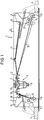
- Figure 1 shows a carrier trough 1 of a recessed ceiling light, this trough 1 is provided with a circumferential support edge 2 which, when installed, abuts the respective ceiling or wall 5 and ensures a flush finish.
- rocker arms 3 are pivotally mounted on the edge, which can be pivoted between a release position, which is shown in solid lines, and a clamping position, which is shown in broken lines. In the release position, the rocker arms 3 are located within the circumferential contour of the carrier trough 1 and rest against a stop 12, so that this trough can be inserted freely into the corresponding ceiling or wall section.
- the pivot bearings 4 of the rocker arms 3 are preferably formed directly on the side wall of the carrier trough and are designed such that the rocker arms 3 can be snapped onto these pivot axes 4, so that simple and quick installation is ensured.
- This embodiment is particularly suitable when the carrier trough 1 or the corresponding side cheeks on which the pivot bearings 4 are molded are made of plastic.
- the rocker arms 3 are actuated via a gear 6 which, when actuating an actuating unit 7, must ensure the pivoting of the rocker arms and can be designed as a flat rod gear, but preferably consists of a cable drive with a cable 15, which via fittings 14 with a link lever part 10 two-armed rocker arm 3 is connected.
- rocker arms 3 are pretensioned into their release position, in a particularly simple manner by means of a rubber band 11, which is attached to tabs 16 of the respective tensioning lever part 9 and is held in a wall bracket 17 of the carrier trough 1.
- the rope 15 is guided over a three-point deflection system from two mutually spaced, wall-fixed and in particular semi-ring-shaped guide and deflection elements 12 and a movable deflection element 13 arranged therebetween, with an oppositely curved guide, loosely sliding, which is equivalent to the fact that this Three-point deflection system can be arranged at any point between the two rocker arms 3 and always fulfills its function in the same way.
- the actuating member 8 for the adjustable deflection element 13 runs perpendicular to the tub floor and is accessible from the inside of the tub.
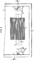
- FIG. 2 shows a top view, partly in section, of the radiation side of the luminaire with a reflector 24, which is asymmetrical in the present case, and an associated lamp 22, which is accommodated in a socket 25.
- This representation also shows the Starter socket 26 with associated starter 27 and a prism cover 23 for the lamp.
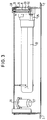
- the sectional view according to FIG. 3 shows the actuator 8 consisting of a screw, which extends through a guide chamber 29 and is rotatably held therein and axially fixed by means of a locking ring 30.
- a polygonal nut 28 is attached, which is non-rotatably connected to the adjustable deflection or tensioning element 13 over which the cable 15 is guided, as can be seen in FIG. 1.
- the guide chamber 29 is expediently designed such that it can simultaneously serve as a carrier for the lamp holder 25.
- the possible one-piece design of the reflector and trough or cheeks is very advantageous, whereby it is not a problem to mount the ballast on the back in the case of a lamp, since this ballast is also accessible by simply removing the built-in lamp due to the problem-free fastening unit.
- a prism cover assigned to the illuminant is preferably fixed to the housing by means of a flexible band, so that all safety aspects are taken into account when changing the illuminant.
Landscapes
- Engineering & Computer Science (AREA)
- General Engineering & Computer Science (AREA)
- Securing Globes, Refractors, Reflectors Or The Like (AREA)
Applications Claiming Priority (2)
| Application Number | Priority Date | Filing Date | Title |
|---|---|---|---|
| DE19526196 | 1995-07-18 | ||
| DE19526196A DE19526196A1 (de) | 1995-07-18 | 1995-07-18 | Befestigungsvorrichtung |
Publications (2)
| Publication Number | Publication Date |
|---|---|
| EP0754906A2 true EP0754906A2 (fr) | 1997-01-22 |
| EP0754906A3 EP0754906A3 (fr) | 1997-05-07 |
Family
ID=7767146
Family Applications (1)
| Application Number | Title | Priority Date | Filing Date |
|---|---|---|---|
| EP96111099A Withdrawn EP0754906A3 (fr) | 1995-07-18 | 1996-07-10 | Dispositif de fixation |
Country Status (2)
| Country | Link |
|---|---|
| EP (1) | EP0754906A3 (fr) |
| DE (1) | DE19526196A1 (fr) |
Cited By (3)
| Publication number | Priority date | Publication date | Assignee | Title |
|---|---|---|---|---|
| EP1617128A3 (fr) * | 2004-07-16 | 2006-11-15 | Audio Partnership Plc | Dispositif de montage amovible |
| EP1873403A2 (fr) | 2006-06-27 | 2008-01-02 | POLYCADFORM e.K. | Dispositif de fixation doté d'une base rotative |
| WO2010049529A1 (fr) * | 2008-10-31 | 2010-05-06 | Osram Gesellschaft mit beschränkter Haftung | Agencement pour le montage de sources lumineuses et procédé correspondant |
Families Citing this family (1)
| Publication number | Priority date | Publication date | Assignee | Title |
|---|---|---|---|---|
| DE102013000030A1 (de) * | 2013-01-04 | 2014-07-10 | Grohe Ag | Befestigungssystem für Einbaubrausen |
Family Cites Families (3)
| Publication number | Priority date | Publication date | Assignee | Title |
|---|---|---|---|---|
| AU411004B2 (en) * | 1969-05-21 | 1971-03-05 | Greendale Engineering & Cables Pty. Limited | Improved support means for recessed light fittings |
| US4424554A (en) * | 1982-09-28 | 1984-01-03 | Lightolier Incorporated | Ceiling fixture with improved mounting means |
| DE4318971A1 (de) * | 1993-06-08 | 1994-12-15 | Semperlux Gmbh | Einspann- und Verriegelungsvorrichtung für Deckeneinbauleuchten |
-
1995
- 1995-07-18 DE DE19526196A patent/DE19526196A1/de not_active Withdrawn
-
1996
- 1996-07-10 EP EP96111099A patent/EP0754906A3/fr not_active Withdrawn
Cited By (4)
| Publication number | Priority date | Publication date | Assignee | Title |
|---|---|---|---|---|
| EP1617128A3 (fr) * | 2004-07-16 | 2006-11-15 | Audio Partnership Plc | Dispositif de montage amovible |
| EP1873403A2 (fr) | 2006-06-27 | 2008-01-02 | POLYCADFORM e.K. | Dispositif de fixation doté d'une base rotative |
| EP1873403A3 (fr) * | 2006-06-27 | 2008-05-21 | POLYCADFORM e.K. | Dispositif de fixation doté d'une base rotative |
| WO2010049529A1 (fr) * | 2008-10-31 | 2010-05-06 | Osram Gesellschaft mit beschränkter Haftung | Agencement pour le montage de sources lumineuses et procédé correspondant |
Also Published As
| Publication number | Publication date |
|---|---|
| EP0754906A3 (fr) | 1997-05-07 |
| DE19526196A1 (de) | 1997-01-23 |
Similar Documents
| Publication | Publication Date | Title |
|---|---|---|
| EP0898686B2 (fr) | Systeme d'eclairage muni d'un corps de base servant de support pour au moins une lampe | |
| EP1201943B1 (fr) | Ecrou à assemblage rapide | |
| DE3538361C1 (de) | Zusatzbremsleuchte fuer Kraftfahrzeuge | |
| DE10314352A1 (de) | Beleuchtungseinrichtung | |
| DE69609675T2 (de) | Verbesserte Befestigungseinrichtung für Signalleuchte eines Fahrzeuges | |
| EP0221242A2 (fr) | Charnière de porte de véhicule | |
| EP0754906A2 (fr) | Dispositif de fixation | |
| CH657415A5 (en) | Sliding door with a holding device | |
| EP2215402B1 (fr) | Dispositif de mise à niveau pour monter une lampe de manière réglable en hauteur | |
| DE102017129186B4 (de) | Rückblickvorrichtung für ein Kraftfahrzeug, Montageverfahren dafür und Kraftfahrzeug mit einer Rückblickvorrichtung | |
| EP0744503B1 (fr) | Dispositif de fixation, notamment des appareils sanitaires | |
| EP2006154B1 (fr) | Phare pour véhicules | |
| EP1559951B1 (fr) | Feu de véhicule et procédé de montage pour feu de véhicule | |
| EP0904980B1 (fr) | Dispositif de fixation d'un feux clignotant | |
| EP0972661A1 (fr) | Conduit d'aération pour véhicule à grand volume | |
| WO2002061331A1 (fr) | Dispositif d'eclairage equipe d'un moyen de fixation | |
| DE69701551T2 (de) | Einbau einer optischen Einheit auf die Fahrzeugkarosserie | |
| DE102024106032A1 (de) | Leuchteneinrichtung, insbesondere Pendel- oder Deckenleuchte | |
| EP0084073B1 (fr) | Collerette pour un luminaire et élément de fixation | |
| DE602004011134T2 (de) | Armaturenbrett eines Kraftfahrzeugs mit Befestigungselementen für ein Instrument | |
| EP1477725A2 (fr) | Lampe murale | |
| DE2841420A1 (de) | Fernsteuervorrichtung | |
| DE19604403A1 (de) | Spreizschloß für eine Duo-Servo-Topfhandbremse | |
| DE202024104937U1 (de) | Optikeinheit, Leuchte sowie Reflektor für eine Optikeinheit | |
| EP0675021A2 (fr) | Dispositif de fixation d'un réflecteur ajustable pour phare de véhicule |
Legal Events
| Date | Code | Title | Description |
|---|---|---|---|
| PUAI | Public reference made under article 153(3) epc to a published international application that has entered the european phase |
Free format text: ORIGINAL CODE: 0009012 |
|
| AK | Designated contracting states |
Kind code of ref document: A2 Designated state(s): AT BE CH DE FR GB IT LI NL |
|
| PUAL | Search report despatched |
Free format text: ORIGINAL CODE: 0009013 |
|
| AK | Designated contracting states |
Kind code of ref document: A3 Designated state(s): AT BE CH DE FR GB IT LI NL |
|
| STAA | Information on the status of an ep patent application or granted ep patent |
Free format text: STATUS: THE APPLICATION IS DEEMED TO BE WITHDRAWN |
|
| 18D | Application deemed to be withdrawn |
Effective date: 19971108 |